FMS EMGZ307 User manual

Operating Manual EMGZ307
Analogue Tension Measuring Amplifier
Version 1.1 10/2009 ff
This operation manual is also available in German, French and Italian.
Please contact your local representative.
Diese Bedienungsanleitung ist auch in Deutsch, Französisch und Italienisch erhältlich.
Bitte kontaktieren Sie Ihren nächstgelegenen FMS Vertreter.
Ce mode d'emploi est également disponible en Français, en Italien et en Allemand.
Veuillez contacter la représentation locale.
Queste manuale d’installazione è disponibile anche in lingua italiana, francese e tedesco.
Vogliate cortesemente contattare la locale rappresentanza.
© by FMS Force Measuring Systems AG, CH-8154 Oberglatt – All rights reserved.

Operating manual EMGZ307
2
1Safety Instructions
1.1 Description conditions
a) High danger of health injury or loss of life
Danger
This symbol refers to high risk for persons to get health injury or loss life. It has to be
followed strictly.
b) Risk of damage of machines
Caution
This symbol refers to informations, that, if ignored, could cause heavy mecanical
damage. This warning has to be followed absolutely.
c) Note for proper function
Note
This symbol refers to an important information about proper use. If not followed,
malfunction can be the result.
1.2 List of safety instructions
Proper function of the Tension Measuring Amplifier is only guaranteed with the
recommended application of the components. In case of other arrangement, heavy
malfunction can be the result. Therefore, the installation instructions on the
following pages must be followed strictly.
Local installation regulations are to preserve safety of electric equipment. They
are not taken into consideration by this operating manual. However, they have to
be followed strictly.
Improper handling may damage the fragile electronic equipment! Don’t touch the
electronic unit! Don’t use rough tools as screwdrivers or pliers! Touch earthed
metal part to discharge static electricity before touching the electronic unit!
Bad earth connection may cause electric shock to persons, malfunction of the total
system or damage of the electronic unit! It is vital to ensure that proper earth
connection is done.

Operating manual EMGZ307
3
Table of Contents
1Safety Instructions ....................................................................................2
1.1 Description conditions 2
1.2 List of safety instructions 2
2Definitions..................................................................................................3
3System components...................................................................................4
3.1 Different EMGZ307 Variants 4
4System Description....................................................................................5
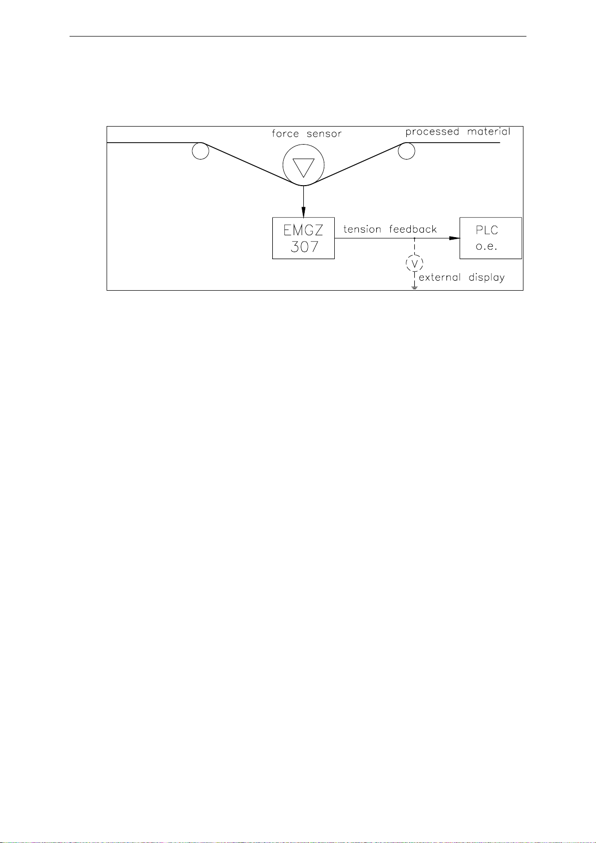
4.1 Functional description 5
4.2 Force sensors 5
4.3 Measuring amplifier EMGZ307 5
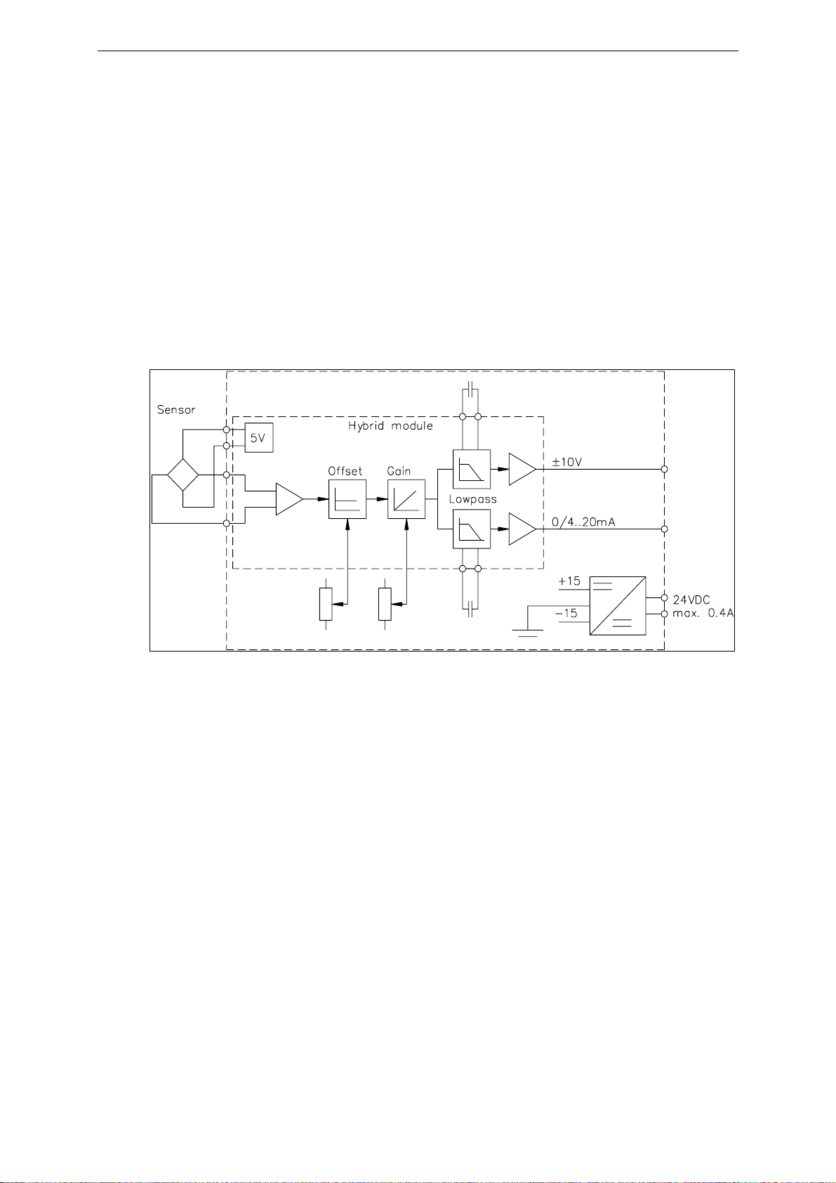
4.4 Block Diagram 6
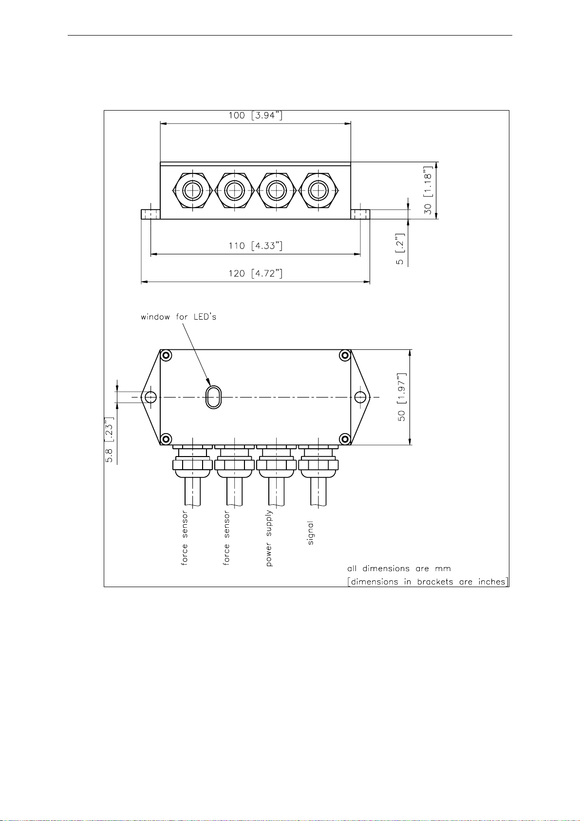
5Dimensions.................................................................................................7
6Installation and Wiring ............................................................................8
6.1 Mounting and Wiring of the Electronic Unit 8
6.2 Mounting the Force Sensors 8
6.3 Wiring 9
7Setting into Operation.............................................................................10
7.1 View of the Setting Elements 10
7.2 Settings for EMGZ307.582388 10
7.3 Configuring Gain and Offset 11
7.4 Configuring the Outputs 12
7.5 Configuring the Lowpass Filters 13
7.6 Calibrating the Measuring Amplifier 14
8Trouble shooting......................................................................................15
9Technical Specification...........................................................................15
2Definitions
Offset:
Correction value for compensation of the zero point difference. Thanks to the offset, it
is ensured that a force of 0N will generate a signal of 0V exactly.
Gain:
Amplification factor for the measuring signal. Use of proper value will set the
measuring range of the sensor exactly corresponding to the signal output range
(0...10V).
Strain gauge:
Electronic component that changes its resistance when its length changes. Strain
gauges are used in the FMS force sensors for acquisition of the feedback value.

Operating manual EMGZ307
4
3System Components
The EMGZ307 consists of the following components (refer also to fig. 1):
Force sensors
•For mechanical/electrical conversion of the tension force
•Force measuring bearing
•Force measuring roller
•Force measuring journal
•Force measuring bearing block
Measuring amplifier EMGZ307
•Hybrid module for supplying the force sensors and amplification of the mV signal
•Robust design with compact aluminium housing (IP67)
•Gain and offset alternatively configurable for infinitely or fixed adjustment
•Freely configurable lowpass filter
•Freely configurable outputs (±10V; 0...20mA; 4...20mA)
•Supports connection of an external feedback display
(Components in italic letters indicate a variant or option)
3.1 Different EMGZ307 Variants
The tension measuring amplifier EMGZ307 is available in two variants:
EMGZ307: Standard 1-channel analogue amplifier
EMGZ307.582388: 1-channel analogue amplifier for rotating applications.
Electronics board is covered with moulding compound to
secure the components and provide protection from centrifugal
forces.
Note
This manual describes the possible setting of the standard amplifier EMGZ307. Some
options, however, are not available in the EMGZ307.582388. For more details refer to
chapter 7 “Setting into Operation”.

Operating manual EMGZ307
5
4System Description
fig. 1: Basic structure of the EMGZ307 Tension Measuring Amplifier E307001e
4.1 Functional Description
The force sensors measure the tension force in the processed material and transmit the
measuring value as a mV signal to the hybrid module in the measuring amplifier
EMGZ307. The measuring amplifier amplifies the mV signal depending on
configuration. The resulting feedback value can be transmitted to an analog
instrument, a PLC or equivalent devices.
4.2 Force Sensors
The force sensors are based on the flexion beam principle. The flexion is measured by
strain gauges and transmitted to the measuring amplifier as mV signal. Due to the
wheatstone wiring of the strain gauges, the measured value is according also to the
power supply. So, the force sensors are supplied from the EMGZ307 by a very
accurate power supply.
4.3 Measuring Amplifier EMGZ307
The EMGZ307 is a single channel analog Tension Measuring Amplifier based on a
hybrid circuit. It is developed specially for use under hard conditions. It is delivered in
a sealed housing compliant with IP67. There can be connected 1 or 2 force sensors of
350Ω. The hybrid module provides the highly accurate 5V power supply and amplifies
the mV signal of the force sensors to a level of 10V and 20mA. Tension and current
output are active the same time. The hybrid technology ensures both good thermal and
electrical characteristics. Measuring circuit and power supply are galvanic insulated.
All settings are done alternatively by 2 trimmers or fixed by jumpers. For filtering of
the signals, non-polarized capacitors can be soldered.

Operating manual EMGZ307
6
Infinite adjustment of gain and offset
Setting by trimmers is used to get a standardized output signal (for ex. 10V) from any
kind of sensor signal. This ensures accurate amplifying of the signal and maximum
immunity to any interference of the signal cable.
Fixed setting of gain and offset
Fixed setting is used when maximum thermal stability and vibration-proof conditions
are needed. The signal is pre-amplified with a fixed value and has to be evaluated
digitally (i.e. by PLC), so that offset and gain can be calculated.
4.4 Block Diagram
fig. 2: Block diagram E307002e

Operating manual EMGZ307
7
5Dimensions
fig. 3: Outline drawing EMGZ307 E307003us

Operating manual EMGZ307
8
6Installation and Wiring
Caution
Proper function of the Tension Measuring Amplifier is only guaranteed with the
recommended application of the components. In case of other arrangement, heavy
malfunction can be the result. Therefore, the installation instructions on the following
pages must be followed strictly.
Caution
Local installation regulations are to preserve safety of electric equipment. They are not
taken into consideration by this operating manual. However, they have to be followed
strictly.
6.1 Mounting and Wiring of the Electronic Unit
The aluminium housing of the measuring amplifier may be mounted to any place in
the machine, but usefully a position close to the force sensors is chosen. Wiring to the
terminals is done according to wiring diagram (fig. 4).
6.2 Mounting the Force Sensors
Mounting of the force sensors is done referring to the FMS Installation manual which
is delivered together with the force sensors.
Wiring to the terminals of the electronic unit is done according to wiring diagram (fig.
4).
Note
Connecting the shield of the signal cable to the electronic unit and to the force sensor
may cause ground circuits which may interfere the measuring signal massively.
Malfunction can be the result. The shield should be connected only to the electronic
unit. On the „force sensor side“, the shield should stay open.

Operating manual EMGZ307
9
6.3 Wiring
fig. 4: Wiring diagram E307004e
There can be connected 1 or 2 force sensors to the measuring amplifier. Using 2 force
sensors, the connections are internally wired parallel. The output signal of the
measuring amplifier then will correspond to the average value of the 2 sensors.
The connection between force sensors and measuring amplifier has to be done using
2x2x0.75mm2[AWG 18] shielded twisted-pair cable. (With cable length below 15m,
2x2x0.25 mm2[AWG 23] is also suitable.) The cable must be installed separate from
power lines.
Caution
Improper handling may damage the fragile electronic equipment! Don’t touch the
electronic unit! Don’t use rough tools as screwdrivers or pliers! Touch earthed metal
part to discharge static electricity before touching the electronic unit!
Caution
Bad earth connection may cause electric shock to persons, malfunction of the total
system or damage of the electronic unit! It is vital to ensure that proper earth
connection is done.
Note
The housing complies with IP67 only if no cable bushing stays open. Therefore, not
needed PG glands have to be closed.

Operating manual EMGZ307
10
7Setting into Operation
7.1 View of the Setting Elements
fig. 5: Wire terminals, switches EMGZ307 E307005e
7.2 Settings for EMGZ307.582388
The special type EMGZ307.582338 for rotating applications has different setting
options as the standard EMGZ307.
For the EMGZ307.582338 following differences exist:
•The offset is preset to “offset fix” see fig.7
•The gain is preset to “gain fix” = 1111 see fig. 7.
•The output current signal is preset to “4..20mA”, see fig. 9
•The electronics board of the amplifier is protected with moulding compound
•The unit is pre-assembled with cables of 8m length.
The wiring of the pre-assembled cables is described in the table below:
Cable Type Terminal Colour Signal Name
Force sensor, 4 wire cable 1 yellow +5V excitation
2 white +signal
3 brown -signal
4 green -5V excitation
Power supply, 2 wire cable 1 brown +24V
2 blue GND
Signal, 3 wire cable 1 brown 0-10V
2 black or
yellow/green GND
3 blue 4-20mA

Operating manual EMGZ307
11
fig.6: Connections EMGZ307.582338 E307009e
7.3 Configuring Gain and Offset
Gain and offset are configured by jumpers. The settings can be made indepently for
gain and offset.
Gain and offset with infinite setting
If gain and offset are adjusted with the
trimmers, the jumpers have to be set
according to fig. 7. Gain and offset then
may be adjusted using the trimmers (refer
to „7.6 Calibration of the measuring
amplifier“).
fig. 7: Jumper setting for infinite gain and
offset adjustment E307006ea

Operating manual EMGZ307
12
Gain and offset with fixed setting
If the signal is processed by a control unit
(for ex. a PLC), configuration with fixed
gain and offset is recommended (offset =
0; gain = 1111). Therefore, the jumpers
have to be set according to fig. 8. With this
configuration, the good thermal
characteristics of the hybrid module are
best utilized. The output signal will be
10V and 20mA when the nominal force of
the sensor is applied.
7.4 Configuring the Outputs
The measuring amplifier provides a tension output (±10V) and a current output
(0...20mA or 4...20mA) which are active simultaneously. The signal of the current
output is configured as follows:
Current output 0...20mA
The jumpers have to be set according to
fig. 9a. This is the standard FMS factory
setting.
Current output 4...20mA
The jumpers have to be set according to
fig. 9b.
fig. 8: Jumper setting for fixed gain
and offset E307006eb
fig. 9a: Jumper setting for current
output 0...20mA E307006ec
fig. 9b: Jumper setting for current
output 4...20mA E307006ed

Operating manual EMGZ307
13
7.5 Configuring the Lowpass Filters
The measuring amplifier provides two lowpass filters. They are used to eliminate
faulty signal variations which may be caused by unbalanced rollers, vibrations of the
machine, or equivalent.
•The lowpass filter U is effective to the tension output.
•The lowpass filter I is effective to the current output.
The lower the cut-off frequency, the more sluggish the output signal will be. The
configuration is made by soldering of a non-polarized capacitor to the soldering points
(refer to fig. 5). The capacitor will be determined referring to the following formula or
list:
Cut-off frequency
[Hz] Capacitor [µF]
1 10
C = 10 / F 2 5
5 2
10 1
C: Capacity [µF] 20 0.5
F: Cut-off frequency [Hz] 50 0.2
100 0.1
200 0.05
500 0.02
1000 0.01
Note
Don’t use electrolytic capacitors because they can’t handle the bipolar signals appied
in this application. They would damage the electrolytic capacitor.

Operating manual EMGZ307
14
7.6 Calibrating the Measuring Amplifier
•Connect gauge to the tension or
current output.
•Connect the first force sensor.
•Check if a positive output signal is
appearing when loading the sensor in
measuring direction. If not, exchange
the two signal wires of the referring
force sensor in the terminal block
(terminals 2 / 3).
•If used, connect the second force
sensor.
•Check if a positive output signal is
appearing when loading the sensor in
measuring direction. If not, exchange
the two signal wires of the referring
force sensor in the terminal block
(terminals 2 / 3).
•Insert material or a rope loosely to the
machine.
•Adjust the offset trimmer until the output value is zero.
•Load material or rope with a defined weight (fig. 10).
•Adjust the gain trimmer until the output value shows the needed value (for ex. 10V
corresponding to 500N).
Note
If the measuring amplifier is operated with fixed gain and offset, signal
conditioning has to be done with additional equipment (for ex. PLC).
fig. 10: Calibrating the measuring
amplifier C431011e

Operating manual EMGZ307
15
8Trouble shooting
Error Cause Corrective action
Output shows signal > 0
although material has
no tension
Offset setting is bad Readjust offset (refer to „7.5
Calibrating the measuring
amplifier“)
Current output is
configured for
4...20mA
Change jumper setting if required
Output signal is not
stable although material
tension doesn’t change
Cut-off frequency too
high Adjust cut-off frequency (refer to
„7.4 Configuring the lowpass filter“)
Ground terminal of
the output isn’t 0V Connect Gnd terminal of the output
(terminal 8) with earth
Adjusting the trimmers
causes no result Jumpers are not set to
„infinite“ Set jumpers to „infinite“
Output shows no
reaction, or 1 or 2
LED’s don’t light
Fuse blown Replace fuse on power supply
Power supply not
correct Check / correct power supply
Measuring amplifier
defect Contact FMS customer service
9Technical Specification
Sensor excitation 5VDC ±20ppm/K max. 30mA [±11ppm/°F]
Gain factor range fixed: 1111; variable: 500...5000
Offset range fixed: 0mV; variable: ±9mV
Temperature drift offset fixed: < 20ppm/K [11ppm/°F]; variable: ca. 50ppm/K
[28ppm/°F]
Linearity error < 0.1%
Tension output ±10V min. 1000Ω
Current output 0/4...20mA max. 500Ω
Lowpass cut-off
frequency adjustable, ca. 1...1000Hz
Power supply 24VDC (18...36VDC) max. 0.1A
Power consumption max. 2.5W
Temperature range –10...+60°C [14...140°F]
Protection class IP67

Operating manual EMGZ307
16
FMS Force Measuring Systems AG
Aspstrasse 6
8154 Oberglatt (Switzerland)
Tel. +41 44 852 80 80
Fax +41 44 850 60 06
info@fms-technology.com
www.fms-technology.com
FMS Italy
Via Baranzate 67
I-20026 Novate Milanese
Tel: +39 02 39487035
Fax: +39 02 39487035
fmsit@fms-technology.com
FMS USA, Inc.
2155 Stonington Ave. Suite 119
Hoffman Estates, IL 60169 USA
Tel. +1 847 519 4400
Fax +1 847 519 4401
fmsusa@fms-technology.com
FMS UK
Highfield, Atch Lench Road
Church Lench
Evesham WR11 4UG, Great Britain
Tel. +44 1386 871023
Fax +44 1386 871021
fmsuk@fms-technology.com
Table of contents
Other FMS Amplifier manuals