Acoustic Image Flex Pre User manual

Flex System
Version Flex R1
Flex Pre
Flex Cab
PAYATTENTION TO THESE SYMBOLS:
IMPORTANT SAFETY INSTRUCTIONS
1) Read these instructions.
2) Keep these instructions.
3) Heed all warnings.
4) Follow all instructions.
5) Do not use this apparatus near water, do not expose to dripping or splashing
water, do not place objects filled with liquid on apparatus.
6) WARNING: to reduce the risk of fire or electric shock, do not expose this
apparatus to rain or moisture.
7) Clean only with a dry cloth.
8) Do not block any ventilation openings. Install in accordance with
manufacturer’s instructions.
9) Do not install near any heat sources such as radiators, heat registers, stoves
or other apparatus (including amplifiers) that produce heat.
10) This apparatus shall be connected to a mains outlet socket with a positive
grounding connection. Do not defeat the safety purpose of the polarized or
grounding-type plug. A polarized plug has two blades with one wider than the
other. A grounding type plug has two blades and a third grounding prong. The
wide blade or the third prong are provided for your safety. If the provided plug
does not fit into your outlet, consult an electrician for replacement of the
obsolete outlet.
11) Protect the power cord from being walked on pinched particularly at plugs,
convenience receptacles, and the point where they exit from the apparatus.
12) Use only attachments/accessories specified by the manufacturer.
13) Use only with the cart, stand, tripod, bracket, or table specified by the
manufacturer, or sold with the apparatus.
14) Unplug this apparatus during lightning storms or when unused for long
periods of time.
15) Refer all servicing to qualified service personnel. Servicing is required
when the apparatus has been damaged in any way, such as power-supply cord
or plug is damaged, liquid has been spilled or objects have fallen into the
apparatus, the apparatus has been exposed to rain or moisture, does not
operate normally or has been dropped.
The exclamation point triangle is used to alert the user to important operating or
maintenance instructions. The lightning bolt triangle is used to alert the user to the
risk of electric shock.
To prevent electric shock, do not remove the top cover.
No user serviceable parts inside. Refer servicing to
qualified service personnel.
To completely disconnect this equipment from the AC
mains, disconnect the power supply cord from the AC
receptacle.

Welcome
The Basics
Flex Cab 3
Power 3
Input and Control Panel 4
Inputs 4
Controls 5
6
Flex Pre 8
Introduction 8
Inputs 8
Controls 8
Control Panel Drawings 9
Signal Flow Diagram 9
Low Cut Filter/Phase Reverse 11
Effects Loop 12
Direct Out 12
Mute Switch 13
Preamp Output 13
Stereo Operation 13
Effects 13
Pseudo Stereo Operation 14
Headphone Output 14
Limiter Switch 14
External Power Option 15
Internal Jumper Options 15
Mounting Options 16
Speaker Placement
Tilt Mechanism 6
Slip Cover and Shoulder Strap 6
Specifications 7
Specifications 17
Care 18
Warranty And Repair 18
Contents
The information in this manual is subject to change without notice. No part of this manual may be
reproduced by mechanical, electronic or other means in any form without prior written permission from
Acoustic Image.
The Acoustic Image logo is a registered trademark of Acoustic Image LLC. Flex, Flex Cab and Flex Pre
are trademarks of Acoustic Image LLC.
1
Welcome to Acoustic Image!
You have purchased a state-of-the-art musical instrument amplifier
system, combining purity, power and portability in a package that sets
a new standard in high fidelity amplification.
Each of our designs is engineered to accurately reproduce the sound
of acoustic and electric instruments, delivering flat frequency
response across the entire musical spectrum; extended, tight, well-
controlled bass; and complete clarity of sound reproduction.
This manual provides operating information for your Acoustic Image
Flex System consisting of a powered 2x10 speaker cabinet (Flex Cab)
and a remote preamp (Flex Pre).
The Basics
The Flex System is a break though in musical instrument amplification
technology. This revolutionary system separates the control function
from the speaker cabinet and puts it at the player’s fingertips providing
ultimate convenience and control over the sound. The system
consists of a tri-amped 2x10 plus tweeter speaker cabinet and a
remotely connected preamp that can be mounted on a music stand or
mic stand within reach of the performer. The Flex System is the
smallest and lightest 2x10 combo system on the market today.
The features of the Flex Cab powered speaker are:
-Two 10 inch woofers each driven by a 300W class D power
amp
-2.5 inch tweeter with 50W class D power amp
-Standard detachable ac power cord
-Operation over 100V to 240V range with automatic voltage
switching
-Tweeter level control
-Downfiring woofer controls (low cut and level)
-Through connection for daisy chaining other cabs
-Power/signal interface for preamp (RJ45/Cat5)
-Lightweight structural foam cabinet with spring-loaded tilt
mechanism
The features of the Flex Pre two-channel preamp are:
-Separate XLR and 1/4 inch inputs per channel
-48V phantom power and 10 dB gain select for mic input
-Input level control per channel
-Four band EQ per channel
-Selectable phase reverse and sweepable low cut filter per
channel (phase reverse can be converted to low pass
speaker emulation filter with internal jumper option
-Effects loop per channel
-Selectable reverb and delay effects with level and rate
controls and pseudo stereo output

-Direct out with selectable 10 dB pad, pre/post switch and
ground lift
-Powered through cable from Flex Cab or dc power supply
-Headphone output
-Switchable limiter
-Mute switch
-Mono or stereo output
-Selectable internal jumper options for gain and stereo
operation
-High fidelity, low noise operation: 110 dB SNR at direct out
The features of the Flex System are:
-Remote preamp feature offers ultimate in control flexibility
-Preamp mounts magnetically to cabinet when remote
feature is not used
-Flex Pre and Flex Cab can be used as standalone units
While our combos and speakers are designed to play loudly--and
clearly--enough so that you can be heard in most gigging situations,
they are not suited to playing at extreme volumes. Generating high
SPLs may require an additional Flex Cab or augmentation by a larger
house system.
The instructions that follow apply to both the Flex Cab and Flex Pre as
well as the Flex System. Each is discussed in turn.
Note that there are powerful magnets in the vicinity of the
recessed screws in the top of the Flex Cab. Do not place anything
on the top that will be damaged by the high magnetic field. Smart
phones, tablets, laptops, digital recorders, etc. should not be
placed on the top of the cabinet.
2
Flex Cab
Flex Cab Rear Panel
3
Introduction
Power
The Flex Cab is a powered speaker cabinet. The power amp function
is integrated into the speaker cabinet along with the speakers. There
is a power amp for each speaker in the cabinet: a 300W class D amp
for each of the 10 inch drivers and a 50W class D amp for the 2.5 inch
tweeter.A signal flow diagram for the Flex Cab is shown below.
Master
Level
Input
Thru
To Preamp DF
Level
DF
Freq
Cutoff Tweeter
Level
Power
Thermal
Model # 660 PS
S/N 6P 0001
AC Input
100-240 V
50/60 Hz
600 Watts
~
Power Switch
Fuse
Auto
Voltage
Switch
0dB -6dB
CAUTION
RISK OF ELECTRIC SHOCK
DO NOT OPEN
Power Amp/Power Supply Power Amp/Power Supply
Auto Line
Voltage
Switching
Voltage Select
AC AC
AC
In
Power Supply for
Remote Preamp
Input
Thru
Connection
Master Level
FF Woofer
Tweeter
DF Woofer
Signal/Power
to/from Flex
Pre
Tweeter
Amp and
Xover
Tweeter Level
Control
0dB -6 dB
DF Cutoff Freq
DF Level
RJ-45

4
To turn on the Flex Cab, plug the detachable AC power cord into the
receptacle on the back of the amp and into a wall outlet. A power
switch next to the AC input turns on power illuminating a “power on”
indicator on the panel.
Note that a spare fuse is
mounted inside the drawer.
The Flex Cab operates with AC voltages between 100V and 240V,
50/60 Hz. An internal switch automatically selects the correct mode of
operation for the voltage range. No user action is required to set the
unit to operate with different AC voltages. Note that the correct AC
power cord must be used for connection to the appropriate wall plug. If
you do not have the right cord, you can buy one from an electronics or
computer store.
Note that when the power switch is off and the power indicator is off,
power is not completely removed from the amp. To completely remove
power, disconnect the power cord. Always leave the power cord
accessible so that you can easily disconnect power from the unit.
The RJ-45 jack located just below the AC inlet is the interface for the
Flex Pre. Both power for the preamp and signal connection from the
preamp to the Flex Cab are provided through this jack. When using
the Flex Pre, connect it to the jack using the supplied Cat5 cable
before turning on the Flex Cab. The maximum length of the Cat5 cable
is 100 feet. Turn the power off before disconnecting the cable.
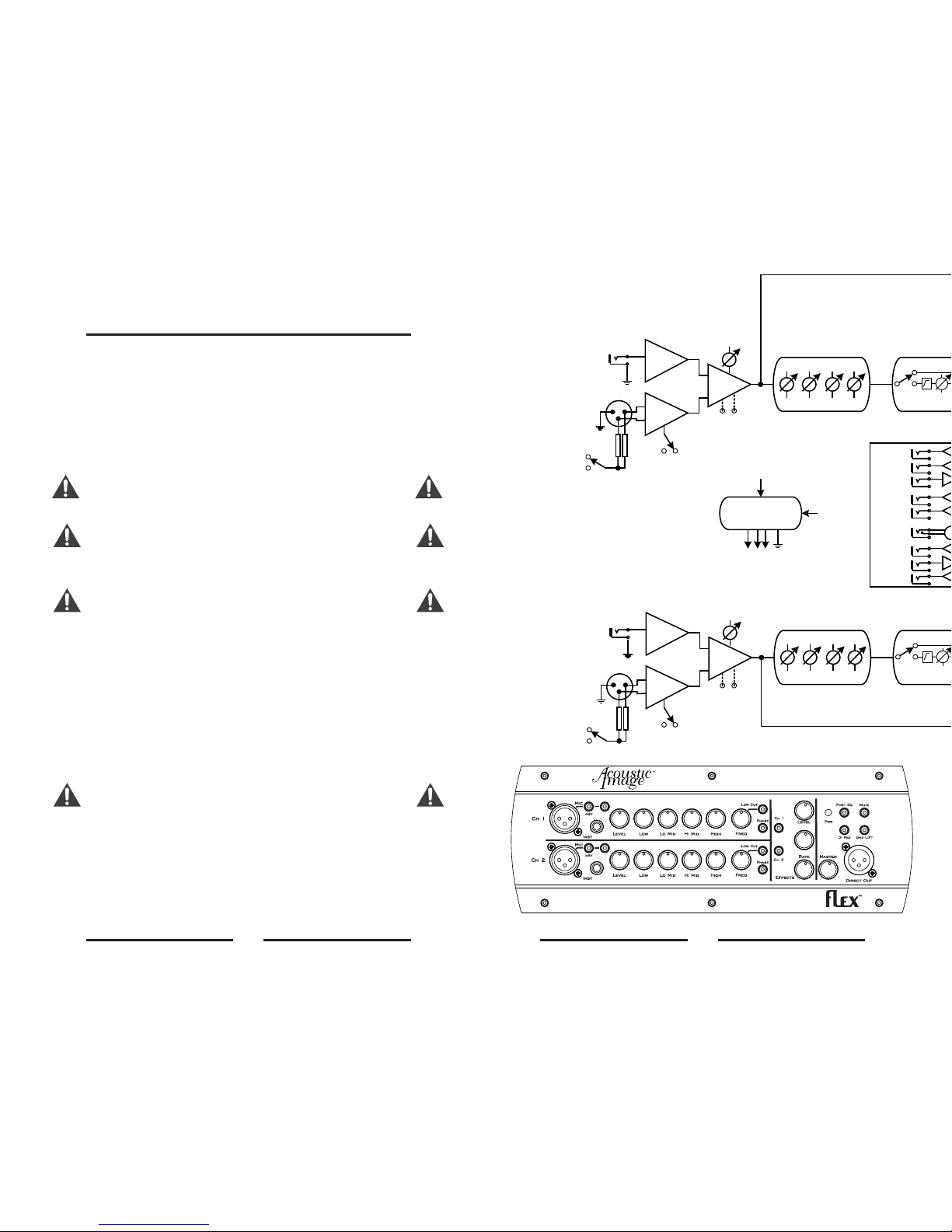
Refer to the rear panel diagram. The inputs and controls for the Flex
Cab are located on the rear panel. The function of each is described
below. Refer to the signal flow diagram on page 3 for more detail.
There are two input jacks for the Flex Cab: an RJ-45 jack that provides
power to and receives signal from the Flex Pre and a 1/4 inch jack that
accepts an unbalanced input from most commercial preamps.
A 6.3-amp fast blow fuse is mounted in the
drawer marked with the fuse symbol that is part of the AC
receptacle. To replace the fuse, turn off the amp, remove the AC
cord and use a small screwdriver to pry the drawer out of the
receptacle. Remove and replace the fuse.
Note that there is a 5 to 10 second delay after the power has been
turned before the amp becomes operational. This is done so that
“start up” noises are not heard.
Inputs
Note
that when a signal is input to the 1/4 inch jack, the RJ-45 input is
disconnected.
The 1/4 inch input jack is only for instrument and line level
signals from a preamp or other source. Do connect a speaker
output to this jack. The input circuit will be damaged.
Input and Control Panel
not
5
The thru jack on the panel is for connecting a second Flex Cab (or
other powered speaker cabinet). Use an instrument cable with 1/4
inch jacks to connect from the thru output to the input of the second
cabinet. Several units can be daisy chained in this way if desired.
There are four controls on the Flex Cab rear panel. The first is a master
level pot that controls the overall output level of the unit. Typically, this
control would be set at maximum (fully clockwise) when using the Flex
Pre as the input source. When using other preamps, the control may
have to be set at a different level to accommodate the signal level of a
particular preamp.
The downfiring (DF) woofer has two controls for affecting the low end
frequency response and the output level. The DF cutoff freq pot is a
sweepable, 12 dB per octave low cut filter that reduces the low
frequency output of the DF woofer in order to reduce the “boominess”
of the cabinet in those acoustic settings where there is too much bass.
Turn the control clockwise to reduce the output. When the control is
fully counterclockwise, the filter is set a 30 Hz, when it is fully
clockwise, it is set at 150 Hz.
The DF level control reduces the output of the DF woofer by 6 dB when
it is engaged. This control also will reduce boominess. The filter and
the level controls can be used independently or together. You should
experiment with these controls to hear how they affect the sound so
that you can best use them in playing situations. Note that these
controls are subtle in their effect in normal playing conditions, but their
effect is easily heard in difficult acoustic conditions and you will find
them to be useful when you need them.
The tweeter level control affects the output of the 2.5 inch tweeter.
When the control is set so the dot is straight up, the output is at the
same level as the other speakers giving the cabinet a balanced sound,
with a flat frequency response. If more treble is desired, turn the
control clockwise. Up to 6 dB of boost is available. If you want to
reduce the treble output, turn the control counterclockwise. Up to 10
dB of cut is available. You should experiment with this control so that
you can find the setting that sounds best to you.
There is a thermal overload indicator located above the power on
indicator. This indicator will be illuminated if the temperature of either
of the power amps inside the cabinet gets too hot. The amps will shut
off under this condition so if you loose output from the unit, check to
see if the thermal light is on. It’s very unlikely that you will ever
encounter this situation under normal playing conditions since the
amps have plenty of heat sinking to prevent thermal overload. Avoid
placing the cabinet in direct sunlight on a hot summer’s day since that
can add considerable heat inside the cabinet.
Controls

6
Speaker Placement
Tilt Mechanism
Slip Cover and Shoulder Strap
Note that there are powerful magnets in the vicinity of the
recessed screws in the top of the Flex Cab. Do not place anything
on the top that will be damaged by the high magnetic field. Smart
phones, tablets, laptops, digital recorders, etc. should not be
placed on the top of the cabinet.
The omnidirectional low frequency output of our speaker cabinets
makes speaker placement relatively noncritical. You will easily be
heard all over the bandstand no matter where one or more arelocated.
However, best results are obtained when the cabinet is placed on the
floor. Putting the unit on a shelf or stand will reduce bass frequencies.
There may be circumstances where this is desirable. Feel free to
experiment to find the sound that is best for you.
In some settings, such as a hollow stage or small, “boomy” room, your
amp or enclosure will produce too much bass. One way to cut
unwanted bass output is to use the built in tilt back feature to lift the
front of the cabinet, reducing the coupling to the floor. To do this, pull
the stand into its forward position and set the combo in place on the
floor. The stand is spring loaded so when you pick up the unit, the
stand will spring back into its storage position. You may want to use
the tilt stand at all times in order to aim the high frequency output of the
speaker toward your ear so that you can better hear the amp.
The supplied slip cover is fitted to the Flex Cab. To install it, slip it over
the top of the cabinet and line up the holes in the cover with the handle
openings on the cabinet.
To use the shoulder strap to transport the cabinet, feed the strap
through the handle opening on both sides and clip the end to the D-
ring attached to the strap. The picture below illustrates how to attach
the strap. The strap can be used either with the slip cover in place or
not in place.
7
Specifications-Flex Cab
System
Electronics
Speaker System
Supplied Accessories
Available Accessories
Frequency Response 30 Hz-18 kHz (40 Hz-14 kHz ±3 dB)
Max SPL 118 dB/m
AC Power 100V to 240V (50/60 Hz), automatically
switched
Size 14”Hx15”Wx13”D
Weight 32 lbs
Flex Pre Interface Balanced signal, power and ground
through RJ-45 connector, Cat5 cable
Input Connector 10k ohm impedance, unbalanced, line
level signal
Thru Connector 10 k ohm impedance, unbalanced
DF Filter 30 Hz to 150 Hz, 12 dB/oct, sweepable
DF Level Control 0 dB, -6 dB, switchable
Tweeter Level Control -10 dB to +6 dB
Woofer Power Amps 2 at 300W rms each, class D
Tweeter Power Amp 50W rms, class D
Woofer Dual 10 inch, one downfiring, one
forward firing
Tweeter 2.5 inch
Crossover Active, 12 dB/oct
Fitted slip cover with shoulder strap
Padded gig bag with shoulder strap
made by Mooradian

8
Introduction
Preamp
The Flex Pre is a two-channel preamp designed to work in conjunction
with the Flex Cab (or other powered cabinets) to implement a versatile
musical instrument amplification system. Or, it can operate as stand
alone preamp/direct box for performing or recording situations. It is a
high performance unit that combines two channels with four band EQ,
sophisticated filtering and digital effects into a compact unit. A signal
flow diagram is shown on page 9 along with illustrations of the front
and rear panels. Refer to these as needed when reading the following
description.
Note that all of the push button switches illuminate when they are in
the “on” position. So, a quick glance at the preamp will tell you which
functions have been engaged.
Also note that there are a few internal jumper options that can be
accessed when the front panel is removed. These options are
intended for the advanced user. They are available to add additional
functionality and are referenced in the description below. The jumper
locations are shown on page 13 and are noted on the signal flow
diagram.
Separate 1/4 inch and XLR jacks are used for the inputs to each
channel of their preamp. The 1/4 inch input has a 1 megohm input
impedance that is optimized to get the best sound from piezo pickups.
The XLR input is a low impedance balanced input with sufficient gain
to allow microphones to be plugged into it. There is a switchable 10 dB
gain to accomodate mics that need more gain. Phantom power is
available through the connector for powering a mic or outboard
preamp and can be activated using the push button switch located
next to the connector.
The
input jacks are separately buffered so both can be used at the same
time. Each channel is identical and can be blended to mix two
instruments, 2 microphones or a mic and an instrument thereby
performing much like a small PA system.
The Flex Pre has the following controls in each channel: input level,
Low, Lo Mid, Hi Mid and High tone controls. In addition, there is a
variable frequency low cut filter and a phase reverse switch in each
channel and a master level control that affects both channels.
Note that when the Flex Pre is used with the Flex Cab, there is a 5
to 10 second delay after the power has been turned before the
amp becomes operational. This is done so that “start up” noises
are not heard.
Inputs
To avoid an audible “pop”, set the input level
control all the way off when switching on the phantom power.
Controls
Flex Pre
Signal Flow Diagram
9
Low High
Lo Mid
Freq
Tone
Controls
Ch1 Pre Out
Ch1 Effects
Loop
Ch2 Pre Out
Ch2 Effects
Loop
Headphone
I/O Boar
Hi Mid
Low Cut
Low High
Lo Mid
Freq
Tone
Controls
Hi Mid
Low Cut
Power Supply
From
Flex
Cab
48 +V -V
From
18V
Ext
Supply
+10 dB
-6 dB
gain
jumper
-6 dB
gain
jumper
+10 dB
Ch 1
Ch 2
Phantom
Power
Phantom
Power
Input
Level
Input
Level
Simulated
Stereo Output
Note: all switches are illuminated
when in the on position
1 Reverb
2 Del/Rev
3 Delay
10dB
2
1
3
Off
10dB
Front Panel

10
Filter
Headphone
Amp
I/O Buss
d-Rear Panel Output to
Flex Cab
(RJ-45)
Phase Inv
Spkr Em
(Optional)
Filter
Phase Inv
Spkr Em
(Optional)
Effects
Prog Select LevelRate
Ch 2
jumper
Effects
On/Off
Effects
On/Off
Gnd Lift
Direct Out Pre/Post
10 db
Pad
Master
Level
Mute
Rear Panel
Snd
Rtn
DC in
18V 400mA
H/P
Effects Loops
Preamp Out Stereo Out
Limiter
Off On
L
R
Ch 1
Ch 2
Sig/Pwr
Interface
11
Level
Tone
The input level controls the level of the signal at the input stage of the
preamp. The master volume controls the level of the signal at the
output of the preamp (at the input of the Flex Cab or other powered
cabinet). Set the master control at “12 o’clock” and the input level at
zero. The input level should then be used to control the overall output
of the unit. The two controls are provided to allow independent control
of “house” volume and “stage” volume when the unit is used as a stage
monitor with a connection to a house PA. See the discussion under
“Direct Out” below.
If you have an instrument with a particularly “hot” output such as an
active bass guitar and you find that the front end of the preamp is
clipping or being overdriven, a 6 dB gain reduction option is available
via a jumper on the preamp control printed circuit board. How do
access and utilize this option is described in “Jumper Options” section
found on page 15.
Each tone control has a center detent at the flat position. Experiment
with the controls to achieve the frequency balance that sounds best to
you. In general, small values of boost and cut are best. The Flex Pre
is designed with flat frequency response so only minor corrections
should be required to compensate for room effects or “peaky” pickups
in order to maintain the balanced response desired for acoustic
instrument amplification. To minimize electronic noise, avoid
operating all controls simultaneously at their maximum settings. The
Low control is a shelving-type that affects frequencies below 150 Hz
and with a maximum boost/cut of 12 dB. The Lo Mid control affects
frequencies between 70 Hz and 700 Hz (peak at 250 Hz) and has a
maximum boost/cut of 12 dB. The Hi Mid control affects frequencies
between 700 Hz and 3000 Hz (peak at 1200 Hz) with a maximum
boost/cut of 12 dB. The Hi control is also a shelving-type that affects
frequencies above 3500 Hz with a maximum boost/cut of 12 dB.
The Flex Pre has a sweepable low cut filter and phase reverse switch
in each channel. The low cut filter is a variable frequency type that
inserts a 12 dB per octave rolloff at frequencies between 30 and 150
Hz, depending on the position of the control. The low cut filter is used
to reduce the bass output in cases where room location or
instrument/pickup combination results in “boomy” sound. Press the
on/off switch to turn on the filter circuit. Start with the frequency control
fully counterclockwise and gradually turn it clockwise until the desired
effect is achieved. The frequency range of the control is limited in
order to give you more control in the critical low frequency range. As a
result, the effect you hear in normal circumstances may be subtle, but,
Low Cut Filter/Phase Reverse/Speaker Emulation Filter

12
you will hear the effect in a boomy bass situation. Experiment with the
position of the control to give you the sound you like best.
The phase reverse switch is used to reduce feedback and to control
phase interactions between the two channels. If you are using two
pickups or a mic and a pickup, you will find the phase reverse switch to
come in handy. Phase related interactions between a mic and a
pickup or two pickups can be cleared up by reversing the phase of one
of the channels. Mic feedback can be reduced by reversing the phase
of the signal. You should experiment with the phase reverse switch to
see if the effect is one that you like.
If desired, the phase switch can be converted to a speaker emulation
filter by moving a jumper on the rear of the Flex Pre circuit board. How
this is done is described in the section entitled “Jumper Options.” This
can be done on either or both channels.
The speaker emulation filter is a low pass filter that modifies the
preamp output to sound like a single speaker guitar amp. It rolls the
frequency off starting a 4 kHz. If you are a guitar player, you may find
this to be a desirable sound, it will allow you to get a more “classic” jazz
guitar sound.
The Flex Pre has an output (“Send”) and input (“Return”) capability in
each channel to allow you to use effects boxes. The effects loop for
each channel is located on the rear panel of the unit. See page 10 for a
diagram of the rear panel. The send output is affected by the input
volume and tone controls and can also be used as a preamp output for
driving other power amplifiers. Because the effects loop is a parallel
type, plugging something into the send output does not interrupt the
signal path. So, a tuner can be plugged into the send output without
affecting the signal going through the amp.
The return input can also be used as an auxiliary input for connecting
other line level signals such as a CD player.
An XLR jack is provided for a Direct Out connection that allows the
preamp output to be fed to mixing boards of house PA systems or
recording studios. As a result, the instrument(s) connected to the unit
can be recorded or further amplified by the house PA system. The
direct out jack is located on the front panel of the Flex Pre. The Direct
Out signal is the combined output of the two channels.
A switch is provided to allow you to select whether the output from the
Direct Out jack is affected by the tone controls (post EQ) or not (pre
EQ).
Effects Loop
Direct Out
13
With the switch in either the pre or post EQ position, the input level
control affects the level of the Direct Out signal, the master level does
not. This allows independent adjustment of the “stage” volume (the
volume coming from the connected speaker system) and the “house”
volume (the volume in the house PA system) when the unit is used with
a stage monitor. Once the level has been set for the house, if more
volume is needed on stage, the master level can be increased. This
will increase the stage volume but not the volume in the house PA.
A ground lift switch is available to “lift” the ground from the output of the
direct out--reducing noise should a ground loop create hum when the
unit is connected to a mixing board.
If the direct out signal is overdriving the mixing board, switch in the 10
dB pad to reduce the signal output level.
A switch is provided to allow you to mute the output of the Flex Pre
without having to turn the amp off. This will allow you to tune your
instrument on stage without being heard. The amp output and direct
out signals are both muted by the switch. The mute switch is on the
front panel and when it is on, the switch is illuminated.
The Flex Pre is connected to the Flex Cab via the RJ-45 jack. There
are 1/4 inch jacks labeled “Preamp Out” on the rear panel for
connecting the unit to other powered cabinets. When the Flex Pre is in
mono mode, the top jack, labeled “Ch 1” or “Mono” is the output to use.
An internal jumper option is available to allow the Flex Pre to operate
in true stereo mode. The output of channel 2 can by disconnected
from the jack labeled “mono” on the rear panel and connected to the
channel 2 output jack by changing the position of a jumper on the
backside of the preamp control board (see the “Jumper Options”
section for details). When in true stereo mode, the output of each
channel is independently available from each preamp output jack.
Note that when in the stereo mode, channel 2 is no longer connected
to the Rj45 output, so it will not be heard through a Flex Cab connected
to the Flex Pre.
The Flex Pre has a high-quality, 24 bit digital effects processor. Three
variable effects are available: a reverb with variable decay time, a
reverb/delay with variable delay, and a delay with variable delay time.
A four position switch selects the program (Off, Reverb, Delay/Reverb
Mute Switch
If you are not
getting any sound out of the amp, check to make sure that the
mute switch is off.
Preamp Output
Stereo Operation
Effects

14
and Delay). There are illuminated switches to select which of the two
channels is processed by the effects unit. Either channel can be
connected to the effects unit. If both switches are engaged,
theselected program appears in both channels. A level control affects
the amount of effect that is heard in the signal (the “wet/dry” mix) and
another control affects the rate of the effect (reverb decay time or
delay time). For example, the rate control has enough range that the
Reverb program can be varied from a large hall to a small room. You
should experiment with both the program selection and the level and
rate controls to find the sound that you prefer. When effects are not
used (program switch in the off postion), the switches for both
channels should be off and the level control should be turned fully
counterclockwise.
The effects processor in the Clarus preamp is a stereo unit.As a result,
a single input can be converted to a stereo output as far as the effects
are concerned. The 1/4 inch jacks labeled “Stereo Out” on the rear
panel are where the pseudo stereo signals are accessed. To operate
in pseudo stereo mode, plug an instrument into channel 2 (
) and connect a separate powered speaker (such as the
Flex Cab) or power amp and speaker combination to each of the
“Stereo Out” jacks located on rear panel. The effects level control
affects the wet/dry mix and the input level control affects the overall
level of the signal. The master level control has no effect. You should
experiment with the operation of the pseudo stereo mode to find the
sound you like best.
There is headphone output on the rear panel of the Flex Pre. You can
plug a standard 1/8 inch stereo plug into this output to connect a
headphone for private listening. If your headphone has a 1/4 inch
plug, you can buy an adapter to allow you to use the 1/8 inch output
jack.
When you plug into the jack, the preamp output is muted. Sound will
only be heard through the headphones. The headphone is connected
to the output of the preamp so all of the controls on the preamp,
including effects, will be heard through the headphone. When the
headphone plug is removed from the jack, the amp will come back on.
Anytime anything is plugged into the headphone output jack, the amp
will be muted so make sure that nothing is plugged into the jack when
you want to use the amp normally.
Pseudo Stereo Operation
only
channel 2 has this feature, connecting to channel 1 won’t work in
this mode
Headphone Output
The headphone output is to be used only for connecting a
headphone unit, do not use it as line out or to drive a low
impedance speaker.
Under extreme playing conditions such as high volume or when
driving a low impedance speaker load, the amplifier and speaker
system connected to the Flex Pre may be pushed beyond their limits.
When that happens, you will hear high distortion and, if connected to
the Flex Cab, you may even cause the overcurrent protection circuit to
operate resulting in an interruption of sound. The limiter switch,
located on the rear panel of the Flex Pre, is provided to allow the amp
to operate under these conditions with lower distortion or without
having the overcurrent circuit kick in. The limiter reduces the peak
signal that is driving the power amp, thereby reducing its peak output
with the result of lower distortion. If you find yourself having to play in
extreme conditions that cause the amp to have too much distortion or
even signal interruption, engage the limiter and see if that helps the
situation.
If the Flex Pre is to be used in an application without the Flex Cab, the
supplied power supply can be used. Simply plug the supply into the AC
outlet and then plug the output of the supply into the power jack on the
rear panel. The external power supply operates from 100V to 240V
AC, so the Flex Pre can be used in standalone mode anywhere in the
world. The appropriate adapters for the ac plug are included.
On the back side of the Flex Pre circuit board are several user-
selectable options: one selects the gain level in the input stage,
another selects between a phase reversal and a speaker emulation
filter and the last disconnects channel 2 from the output buss and
connects it to an output jack. To access the back side of the circuit
board, remove the 6 allen-head screws on the preamp front panel and
lift the preamp module out of the chassis.
Aphoto of the back side of the circuit board is shown below:
Limiter Switch
External Power Option
Use only the external power supply provided by Acoustic Image,
otherwise, the Flex Pre may not operate properly.
Internal Jumper Options
15
Gain Jumpers
Filter Jumpers
Ch 2 Jumper

Looking closely at the circuit board in the vicinity of the jumpers, you
can see that each has a label that tells you the option that has been
selected by the jumper. The Gain Jumper is labeled “Norm” or “-6 dB.”
If the shunt is under “Norm,” the normal gain option is selected. The
Filter Jumper is labeled “Invert” or “LP.” If the shunt is under “LP,” the
low pass filter, or speaker emulator has been selected. As you can
see, each channel has the jumper option, so you can select the same
or a different option for each one. The Ch 2 Jumper is labeled “Out” or
“In.” If the “In” position is selected, channel 2 is disconnected from the
output buss and is connected to the Ch 2 Preamp Out jack on the rear
panel. (Hopefully that nomenclature is not too confusing.)
Once you have made the jumper selections you want, reinstall the
preamp panel in the chassis.
The Flex Pre can be mounted just about anywhere that puts it where
you want it. It will attach magnetically to the top of the Flex Cab. Simply
position the front feet on the bottom of the chassis in the recessed
holes in the top of the Flex Cab and the magnets will hold it in place. It
will sit on a table top or it can be mounted on a mic stand with the
included adapter. An available mounting bracket (On-Stage Stand
MY550--available from Sweetwater.com) will allow you to mount the
unit on the side of a music stand or mic stand.
Mounting Options
Note that there are powerful magnets in the vicinity of the
recessed screws in the top of the Flex Cab. Do not place anything
on the top that will be damaged by the high magnetic field. Smart
phones, tablets, laptops, digital recorders, etc. should not be
placed on the top of the cabinet.
16
Specifications-Flex Pre
Mechanical
System
Controls and Inputs
Effects
Output Interface
Supplied Accessories
Optional Accessories
Size 2.5”Hx11.5”Wx5”D
Weight 2.5 lbs
Frequency Response 20 Hz - 20 kHz (±0.5 dB)
Signal to Noise Ratio >110 dB at direct out
Power Proprietary through RJ-45 connector or
18V via DC adapter (AC 100V to 240V)
Mic Input 600 ohm balanced, XLR connector,
switchable 10 dB gain
Phantom Power 48 volts, on/off switch w/LED indicator
Instrument Input 1 M impedance, 1/4 inch jack
Direct Out +4 dB, balanced, XLR, ground lift,
pre/post EQ selector, switchable 10 dB
pad
Effects Loop Parallel type
Low Control Shelving type, ±12 dB at 50 Hz
Low Mid Control ±12 dB at 250 Hz
Hi Mid Control ±12 dB at 1200 Hz
Treble Control Shelving type, ±12 dB at 8 kHz
Low Cut Filter -12 dB/octave sweepable from 30 to 150
Hz
Phase Reverse Switchable 180 degree phase reverse
Speaker Emulator (if selected) -12 dB/octave at 4 kHz
Type 24 bit digital with 3 programs
Programs Reverb with variable decay time,
Delay/Reverb with variable delay time
Delay with variable delay time
All have variable wet/dry mix and
“pseudo stereo” capability
Proprietary balanced signal and power
interface via RJ-45 connector (100 ft
max Cat5 cable length)
1/4 inch unbalanced outputs
Padded gig bag, 10 ft Cat5 cable, mic
stand adapter, DC power supply and
AC plug adapters
Mic stand mounting bracket
W
17

Care
Warranty and Repair
Acoustic Image combos and cabinets are made from injection molded
polymer materials, the amp heads are made from powder coated
aluminum and steel. A little care will keep yours looking new for years
to come. Use a clean, dry cloth to clean the cabinet and metal parts of
the amplifier.
We stand behind our products with a full warranty of five years from
the date of purchase. Speaker components are warranted for 180
days. Should a problem arise, please call us before returning your
amplifier or enclosure. Naturally, our warranty does not cover
products that have been damaged through misuse. Be sure to check
our web site regularly, we have an FAQ section and we post helpful
information for getting the most out of your Acoustic Image product.
Be sure to check out our YouTube channel which is accessible from
our web site, we have a video version of this manual there.
Warranty Information
Serial Number _______________
Acoustic Image Phone: 919-785-1280
5820 Triangle Drive Fax: 919-785-1281
Raleigh, NC 27617
www.acousticimg.com
18
FCC COMPLIANCE NOTICE
This device complies with part 15 of the FCC rules. Operation is subject to the following
two conditions: (1) This device may not cause harmful interference, and (2) this device
must accept any interference received, including interference that may cause undesired
operation.
CAUTION: Changes or modifications not expressly approved by the party responsible for
compliance could void the user’s authority to operate the equipment.
NOTE: This equipment has been tested and found to comply with the limits for a Class B
digital device, pursuant to part 15 of the FCC rules. These limits are designed to provide
reasonable protection against harmful interference in a residential installation. This
equipment generates, uses and can radiate radio frequency energy and, if not installed
and used in accordance with the instruction manual, may cause harmful interference to
radio communications. However, there is no guarantee that interference will not occur in a
particular installation. If this equipment does cause harmful interference to radio or
television reception, which can be determined by turning the equipment off and on, the
user is encouraged to try to correct the interference by one or more of the following
measures:
--Reorient or relocate the receiving antenna.
--Increase the separation between the equipment and
receiver.
--Connect the equipment into an outlet on a circuit different
from that to which the receiver is connected.
--Consult the dealer or an experienced radio/TV technician
for help.
19

20
© 2013 Acoustic Image LLC
This manual suits for next models
1
Table of contents