Acoustical Manufacturing Co. 405-2 User manual

4052Current
Dumping
Amplifier
Instruction
Book

ouRD4C/5-2
Current
DumpingAmplifier
INSTRUCTION
BOOI<
The
Ouad
405-2 is
capableof veryhigh
output
levels.Read
this
bookthoroughlybeforeconnecting
your
loudspeakers.
CONTENTS
Preambfe PageNumber
Packing ....2
Service ....2
Guarantee ........2
Description .......3
Specification .....10
lnstallation
ACInput... PageNumber
Earthing
(Grounding)
Fuses.
Inputconnection.
Inrrdsnealer aonaAaliof
.
I orrdsnp:kpr nrntpr-t;nn
Orrtnrrl I imitor
Ouadelectrostaticloudspeaker.
Loudspeaker
phasing
Heeclnhnnoc
Addit or'aLlor,dsnpafcrs
The Acoustical Manufacturing Co. Ltd.,
HUNTINGDON,
Cambs.,
PE1
B 7DB.
Telephone
No.: Huntingdon
(O4BO)
52561
Telex: 32348 OUADG
Ouad is a reglstered trade mark
oto59EC
4
5
5
6
6
6
1
7
B
B
I
Packing
Theamplifier
issupplied
withan
input
lead.mainsconnector,
four
speaker
connectors,
two voltage
limitingshorting
links,and
a
spare
mains
fuse.The
packing
material
comprisesa two part
expanded
polystyrene
shell
anda cardboard
carton
andshould
be
retained
for re-usein case
theunit
hasto bereturnedatany
time.
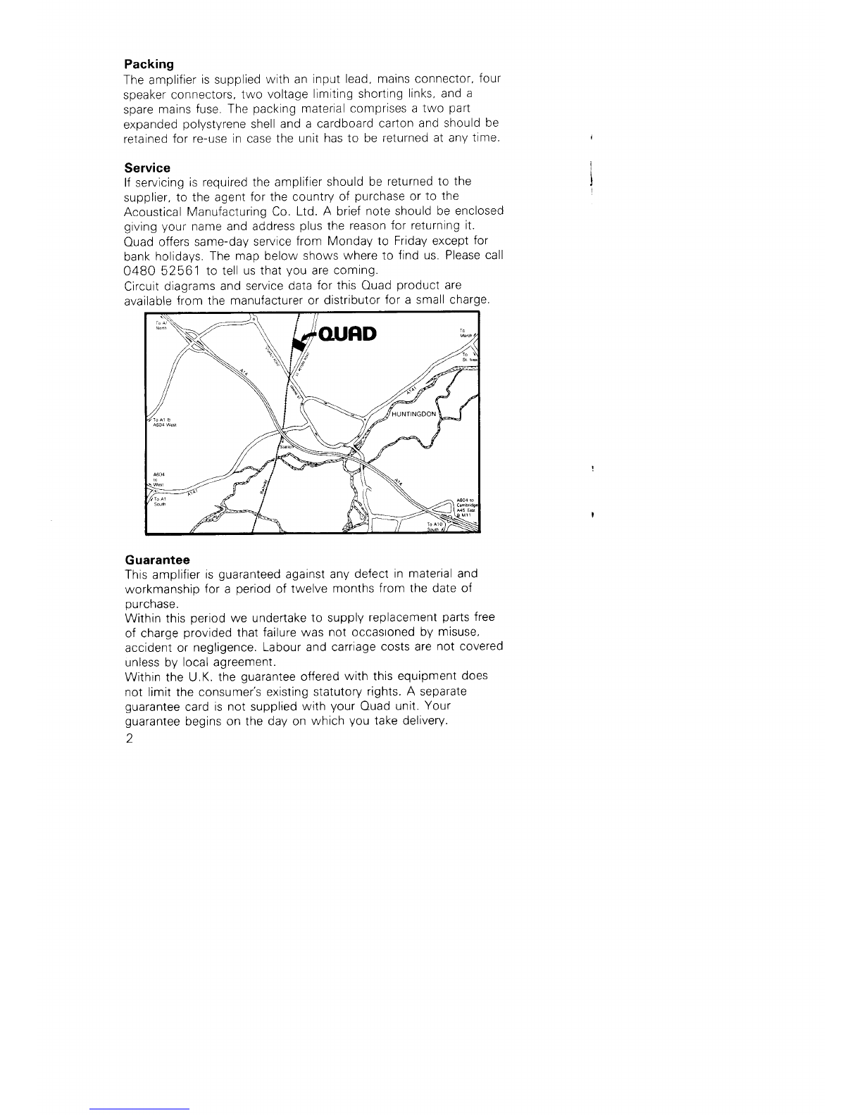
Service
lfservicing
isrequiredtheamplifier
should
be returnedto the
supplier,
to theagent
forthecountry
of purchase
orto the
Acoustical
Manufacturing
Co.Ltd.A brief
noteshouldbe enclosed
givingyour
nameandaddress
plus
thereasonfor returningit.
Ouad
offers
same-daV
service
from Monday
to Fridayexcept
for
bank
holidays.
Themapbelow
shows
whereto findus.Please
call
0480 52561 to tell
usthat
you
are
coming.
Clrcuit
diagrams
andservice
data
forthis
Ouad
product
are
available
fromthe manufactureror distributor
fora smallcharge.
Guarantee
Thisamplifier
is
guaranteed
againstany
defect
inmaterialand
workmanship
fora period
oftwelve
months
fromthedateof
purchase.
Withinthis
period
we undertake
to supply
replacement
parts
free
of charge
provided
that
failurewas notoccastoned
by misuse,
accidentor negligence.
Labourandcarriage
costsare
notcovered
unlessby localagreement.
Withinthe U.K.
theguarantee
offered
withthis
equipment
does
not limittheconsumer's
existingstatutory
rights.A separate
guarantee
card
isnot supplied
withyour
Ouad
unit.
Your
guarantee
beginson thedayon which
youtakedelivery.
)

Description
The
Ouad
405-2 is
a two channel
power
amplifier
primarily
intendedfor use
inhigh
quality
soundreproducingsystems.The
amplifierisusuallyusedwith a Ouad
controlunitthough
other
signalsourcescanreadilybeaccommodaled
Theamplifierusesa currentdumping
outputcircuit,a Ouad
invention
whicheliminatesmanv
of theoroblemsassociatedwith
transistoramplifiers.andcoveredby patents
inseveralcountries.
In
a currentdumpingamplifierthereisin effectbotha low
powered
veryhigh
quality
amplifieranda high
powered
heavyduty
amplifier.Thelow power
amplifiercontrolsthe loudspeakers
at
all
times,
callinguponthehigh
power
sectionto provide
most
of
themuscle.The
smallamplifierisso arranged
- it carries
anerror
signal
- that
provided
thelarger
power
transistors
(the
dumpers)
get
within
thetargetareaof therequired
outputcurrent
itwillfill
in
theremainder
accuratelyandcompletely.Thereproduced
quality
is
solely
dependent
on thesmallamplifierwhich
becauseof its
low
power
canbe madevery
goodindeed.
Problems
of crossover.crossoverdistortion,
quiescent
current
adjustment.thermal
tracking,transistormatching,alldisappear.
Thereareno internal
adjustmentsor a'lignmentsandthechoiceof
power
transistortypesislessrestrictive.
Smplifed Schematc of 405-2 Amplifiershowing
ClassA, Dumpers
and BridgeComponents

The
405-2 isfittedwitha new Ouad-designed
protection
circuit.
This
is
a load-sensitive,time-dependent
current
limiterwhich
overcomes
theproblems
associated
with conventional
"load-line"
circuits
Theamplifier
will
deliveran
instantaneous
maximumcurrentof
B.5A
intoany
load.lf
the
loadistoo reactrve,
orofa resistance
substantially
below
4fl
, thecurrent
limitissmoothlyand
progressively
reducedto a valuewhichenablestheoutput
transistors
to remainwithintheirsafe
operatingarea.
Inthe
extreme
caseofa shortcircuit
thisvalue
is
3.1A.
Whenthesignal
levelfallsor theshort
circuitis
removedthe
current
limit
gradually
returnsto itsinitial
level.
Thisenablestheamplifier
to deliver
high
peak
currents
into
alnrost
any
loadwhenhandlinga normalmusic
programme.
while
fully
nrntp.t;nn tho ^rtnlt deViCeS
frOm SUStained
OVerlOadS
into ShOrt
circuitor purelV
reactive
loads.
Shorting
bothoutputssimultaneously
on signal
foranextended
period(minutes)
isnot protected.
INSTALLATION
TheOuad
405-2 carriesno controls
andmaybe mountedout of
sight
ina cabinetor anyother
convenient
location.
TheOuad
405-2 is
provided
witha substantial
heatsink,and
must
always
beadequately
ventilated,
particularly
if
positioned
in
a
n:hinet nr crrnhn:rd
lf
used
in
close
proximity
to thecontrolunit,
tuneror magnetic
cartridge,
care
should
betaken
to ensurethat
humis
not induced
by radiationfromthemainstransformerof rhe405-2.
Thecurrent
dumping
crrcuittechnique
used
intheOuad
405-2
enables
extra
robusttransistors
to beused
without
impairing
programme
qualrty
andtheamplifier
canoperate
at higherthan
normaltemperatures
withoutcompromising
reliabiiity.
Whenoperated
athigh
power
levels
itis
quite
normal
forthe
heatsinks
to behot
to thetouch.
AC Input
TheOuad
4O5-2issuitable
foruseon either
5OHzor 60Hz,
2OO-24OV
or .iOO-120V
ACsupples.
Beforeconnecting
theOuad
405-2 to the
supply
ensure
thatthe
voltageselector,
located
on therear
panel
is
correctly
set.
Voltages
of upto 10%aboveor belowthe
indicated
rangedo not
affect
performance.
ACmains
inputisviaa standard
three
pin
Euro
plug
supplied
with
theunit
whichshould
bew red
in
accordance
withthe
internationally
agreed
code,Green/vellow
earth,
Brown
liveand
Blueneutral,see
Fig.
'1
.
4

L\e
(Bro^n)
v,G
'\1
Earth
{Green/Ye
ow)
Frg lA
(. Inp-r
Co^necrorC[122
Earthing
(Grounding)
The
Ouad405-2 should
beconnectedto eartheitherthroughthe
signalsourceviathe4-pinDin
signallead
orthroughthethirdwire
of itsAC mainslead,
butnotbothor it may
causehum.
Normally
a 3-coremainslead
shouldbeusedwith
a Ouad34 or
44 controlunit
anda 2-coreleadwiththeOuad33. butif.with
any34 or a 44 after
serlal
number
25800. humoccurswiththe
volume
controlatminimum
and
with
all
othereouioment
disconnectedfrom
thecontrolunit,
thenit is
permissible
to break
theearth
connectionat oneendof theinterconnecting
mainslead,
relying
onthe signalleadto earth
the
amplifierviathe controlunit.
lfthis
doesnot clearthehum
do notoperatewith
theearth
connection
brokenbut investiqate
further
to ascertainthe
cause.
Fuses
Inaddition
to themains
suppiyfuseon
the
rear
panel
ofthe
amplifier,eachchannelis
protected
bytwo internal
fuses,
located
onthe printed
circuitboards.
Themainfuseis
a 2.5 ampsurge-resisting
(2.5AT)
type
ior
2OO-250volt
supplieswhilea 5 amp
surge-resisting
(5AT)
fuse
is
requiredwhenoperatingwith100-1
25 volt
supplies.In
either
case
all
four
internal
fuses
are
4 amp
quick
blowing
(4AF).
To
reach
theinternal
fusesit isnecessary
to remove
the
top cover
of
theamplifier,byundoingthe
two retaining
screws
andsliding
the
coverabout
'1
Omm,
(0.5"),
backwards
beforelifting
it
clear.
Withdrawthe mains
plug
beforeremovtng
thecover.
Therndicatorlampontheamplifieris
powered
from
the*50 voit
supply.lfthe
indicatorlampis
on,themainfuse
must
beintact,
butillumination
of
theindicatorlarnp
doesnotimply
that
the
;^r^.^^l {,,-^^ -.^ ;^+^^+
'trtqt
I oL tu)Y) ctY ilrLqut.

Input Connections
The
inpuileadsupplied
withtheOuad
405-2 shou
d beused
with
signal
sources
otherthan
a Ouadcontrol
unit.
The
phono
plugs
are
marked
L and
Randshould
beconnected
to theappropriate
output
sockets
of
the
pre-amplifier
ormixer.
For
a Quad
control
unit,use
the
4 pir'|4pin Dinleadsupplied
with it. Pin1 is
left,Pin
2 screen.
Pin3 right,Pin
4 blank.
For
remote
installation
longer
runsof screened
cable
maybeused,
butthe
totalcapacitv
ofthe leadshould
notexceed
2OOOpF
per
cnannet.
Loudspeaker
Connections
TheOuad
4O5-2 isfitted
withstandard
4mm socketsand
two red
and
black
plugs
are
packed
wlth
theunrt.
TheOuad
405-2 is
unconditionally
stable
and
maybeused
withany
typeofspeaker
cable.
For
optimum
performance
it is
necessaryto ensure
that
the
impedance
ofthe
cable
issmall
relative
to the
impedanceof
theload.
Each
loudspeaker
should
beconnected
to its
appropriate
amplifier
output
sothat
thetwo pairs
of wiresareconnected
rn
thesame
wav,to ensure
thatthe
speakers
operate
n phase.
Theoutput
terminals
are
colour-coded
to facilitatethis.
Should
there
beanydoubt
the
phasing
canbe
checked
later
experimentally
(See
PageB).
Whereone
loudspeakeroniy
is
used
formono,etther
channel
maybe
usedandtheterm
nalsof
theother
channel
leftvacant.
A dummy
loadresisior
isnot
required,
In
cases
where
louospeakers.
suchas
theelectrostat
c
loudspeaker,
also
requirean
energising
supplV
the
instrrctions
provided
withthe
loudspeaker
should
be
followed.
Each
loudspeaker
should
becapable
of handling
the
full
output
of
the
amplifier,
or
the
protection
facilitydescrbed
beiow
should
beused.
Theoutputs
ofthe
405-2 can
be
connected
inserresor n parallel
to produce
a s
nglechannel
power
amplif
ier
for
special
applications.
A separate
data
sheet
is
ava
lableon requestDo not
attempt
to connect
the
redoutput
terminals
together.
Loudspeaker Protection
Theloudspeaker
manutacturer
usually
states
a maximum
recommended
amplifier
power
for
his
loudspeaker.
lf
this
figure
is
below'1OOW
(into
BQ)
thenthe
iimiter
faciiities
provided
with
the
amplifier
should
be
fitted.
Failureto do so
maycausedamage
to
the
loudspeakerand
infringe
its
guarantee.
Maximumsafe
power
for
most
loudspeakers
is
time
and
frequency
dependent
and
so
isdifficult
to define
precisely
for
a musicsignal
Some
manufacturers
will
permit
their
loudspeakers
to be
used
witn
amplif
iersexceeding
the
quoted
handlingcapacity
provided
certain
orecautions
are
observed.
Thiscan
sometimes
beadvantageous
in
6
{
I
I
enablingshort
durationhighlevel
peaks
to behandled
without
overload.
The
adviceof the loudspeakermanufactureror his
agenl
should
alwaysbeobtainedbeforeembarkingon sucha procedure
Eachchanneloftheamplifier
incorporatesa DCsensing
circuit
whichcutsoff signalto theloudspeakersin the
eventof
component
failurewhichwouldotherwisebe
likely
to damagethe
lou
dspea
kers.
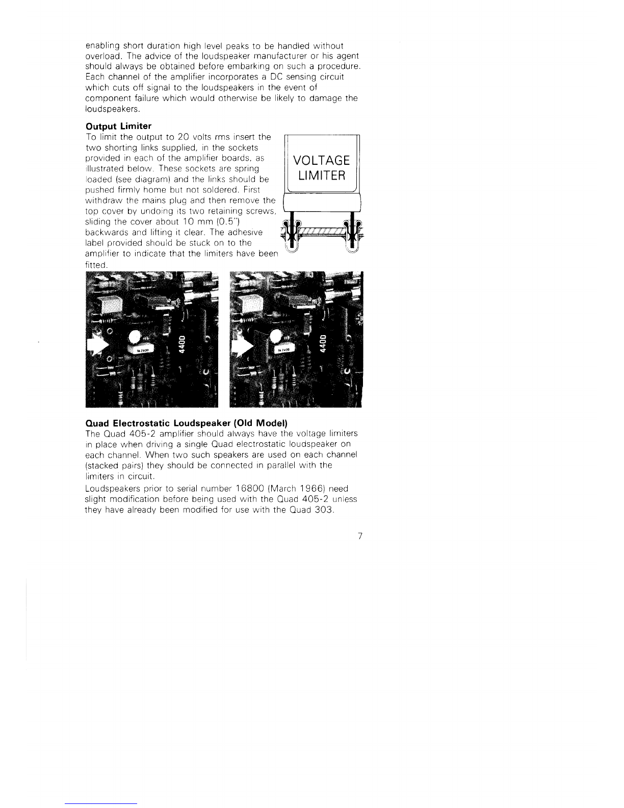
Output Limiter
To limittheoutput
to 20 voltsrmsinsertthe
two shorting
links
supplied,
in
thesockets
provided
in
each
oftheamplifierboards,as
llustrated
below.
These
socketsarespring
oaded
(see
d,agram)and
the
links
shouldbe
pushed
firmly
homebut
not
soldered.
First
withdrawthemains
plug
andthen
remove
the
top coverby undorngrtstwo retarnrng
screws,
sridingthecoverabout
1O
mm
(0.5")
backwarosand
lilting
it
clear.
The
adhesrve
t^L^l ^-^. !^! ^t-^,.r! I
laD€l
provroed
srrouid
De
stirck
onto the
amplifier
to indicatethat
the
limitershavebeen
firted.
Ouad Electrostatic Loudspeaker (Old Model)
TheOuad
405-2 amplifiershould
always
havethevoltage
limiters
in
place
whendrivinga singreOuad
electrostatic
loudspeaker
on
each
channel.
Whentwo suchspeakers
areusedon eacl-rchannel
(stackedpairs)
theyshouldbe connected
inparallel
w,ith
the
limiters
in
circuit.
Loudspeakers
prior
to serialnumber
16800 (March
1966)need
slight
modificationbeforebeingused
with
the
Ouad
405-2 unless
thev
have
alreadv
beenmodifiedfor usewith the Ouad303.

Loudspeaker
Phasing
lfthere
isany
doubt
about
the
way
in
which
the
loudspeaKers
are
connected
(see
Page
6),
their
phasing
may
now be
checked
by
playing
a mono
disc
over
both
channels.
when
the
sound
should
uoo"ai
to emanate
froma point
midway
belween
them lfthis
ls
lndefinrte
the
connections
to either
of
the
loudspeakers,
but
not
both,
should
bereversed.
Correctly
connected
theloudspeakers
will
give
a definite
centre
sound
source
accompanied
bya more
full-bodied
sound
ln
the
tenor
and
bass
registers'
Headphones
HeadIhones
should
beconnected
to the
Ouad
405-2 outputs
in
place
of
the
loudspeakers
and
a typ
cal
wiring
arrangement
is
shown
inFig.
(i).
Any
of
the
headphone
switch
untts
on
the
market
will
provide
the
necessary
swtching
and
many
of
them
also
orovide
for rncorporating
theresistors
which
adiust
thesignal
level
to suit
most
magnetic
headphones.
The
Ouad
405-2 cioes
not
require
dummy
load
resstors.
Electrostatic
orother
types
requirlnga high
level
input
should
be
connected
inaccordance
wlth manufacturers'
lnstructions'
The
loudspeaker
return
leads
(whichmay
be
commoned
lf
n"..rruryi must
be
taken
to theblack
sockets
and
never
to chassis
or
earth.
I
I
I
t
1
I
i
lErr cxltrtruel I
i
I
td
Fig.

Additional Loudspeakers
Fig.
(ii)
showstheswitchingarrangementsif
morethan
one
pair
o{
ioudspeakers
isto be used.The
switch
may
beeither
of therotary
typeor oneof theproprietary
switchboxeswhich
are
readily
ava
ila
ble.
LOUDSPEAKER
SWITCHINGFOR
OUAD
405 SWITCH OPERATION
OUAD 405
LT RT
.I
Fig.
ii

OUAD
405-2
SPECIFICATION
Measurements apply to elther channel, with or without the other
channel operating.
Power Output
The
amplifier
isintended
forusewith loudspeakers
of 41 6A
nominal
impedance.
Power
and
distortionfor
various
frequencies.
Continuous
sinewave
into
BQ resistive
load.
lOO Nz
anylevelup
ro 100 wats < 0.01% D tot
lOOOHz
anylevel
up
to 1OO
watrs
< 0.01%D tot
10.000 Hz
anylevel
upro 100 watts
< O.O5%D tot
For
other
impedances
and
freqrtencies
see
graphs.
i
I
voLts
dBV
LOADRES]SIANCE
OHMS
FREQUENCY
MAXIMUM
OUTPUT VOLTS AS A FUNCTION
OF
FR€OUENCY FOF VASIOUS
LOAOS E DISTOFT]ON
10

Notes:
1.The
curves
showmaximum
shortterm
andlong
term
power
output
into
resistive
loads.
Performance
into
reactive
loads
depends
upon
theimpedance
and
phase
angle
of
theload
and
theimmediatepast
history
of the
signal.
Inpractice
with
loudspeaker
loads
andmusic
programme,
power
output
approximates
to thepeak
power
curve.
2. Withthe
additional
power
limiter
inserted
themaximum
output
voltage
islimited
to 20V + 1O%
(50watrs
BO),
ailother
performance
figures
unchanged.
Output Internal lmpedance and Offset
3.3pH in
series
with
0.03O
Offset
( 7mV.
Frequency Response
Ref.1 kHz
Lowfrequency
-1 dB at 20 l1z.
Filter
attenuation
as
curve.
High
frequency
-O.5dB
20 k1z
-3dB bOkHz.
0
dB
-10
f I ttttil| | tllllll
zts Low FREOUENCy
tNpUT
FTLTER
RESPONSE
, | | lll | |
1OH2 100H2 1KHz
SignalInput
Level
O.5Vrms
+ 0.5d8
for
1OO
watrsinto
Be. Amplifier
loads
the
input
by2OkO
in
parallel
with22OpF.
11
Signal Input Slew Rate Limit
0.1
V4rS.
Provided
therateof change
of inputvoltagesdoes
notexceedthis
figureandthe
amplifier
isnotdriven
intoclipping.then
thetotalof
all
distortionsappearlng
intheaudio
range
(20-20.000 Hz)dueto
transientor repetitive
waveformswith
frequencycomponents
inside
or outside
theaudio
range
willbeat least
BOdB
below
fullrated
power.
lf
themalor
portion
of theinput
energy
is
wantedsignal
then
-BOdB
(0.01%)
representsthe
maximum
possible
distortion
on programme.
Signal Input Overload
Instantaneous
recoveryup to *2OdB overload.
Crosstalk
(lnput
loadedby 1
kA) BOdB@ 1
OO
Hz
70dB
@ 1 kHz
60dB@ '10
kHz.
Hum and Noise
'A'
weighted
-96d8 reffull
power
Unweighted
-93d8 reffull
power(1
5.7 kHzmeasurement
bandwidth).
Protection
TheOuad
405-2 is
suitable
foruseunder
themostarduous
music
conditlons
andiselectrically
protected
by current
limiters;
8.5 amperes
peak
current
into
any
loadreducingto 3.'1amperes
steady
state
into
a shortcircuit.
ShortingbothoutpLrts
simultaneously
foranextended
period
willresultinoverheatingand 1
eventual
breakdown.
Stability
Unconditionally
stable
withany
loadandanysignal.
Power Input
110-1
20-1 30V, 220-230-240V
50-60 Hz,3O-350 wattsdepending
onsignai
level.
Dimensions
Height
115mm (45")
Width 340.5
mm (13.4")
Depth 195 mm \1
7"1
allowanextra
38 mm (1
.5")for
plug
andsocket.
Weight
9 Kg (20 lbs ) prnred
n Ensand
bvcranpress
KnssLy'nn

The Acoustical Manufacturing Co. Ltd.,
HUNTi
NGDON,
Cambs.,
PE-187DB,
Telephone
No.:Huntingdon
(0480)
52561
Telex: 32348OUAD G
Ouad is a regrsteredtradentark I
Other Acoustical Manufacturing Co. Amplifier manuals


