manuals.online logo
Brands
  1. Home
  2. •
  3. Brands
  4. •
  5. Acro Pro
  6. •
  7. Toy
  8. •
  9. Acro Pro SR User manual

Acro Pro SR User manual

AcroProtm Instruction Manual, Page 1
ing at the photo is
all you’ll have to
do to figure out
what’s going on. If
there’s something
about a particular
step that’s critical
or unusual, we’ll
mark that step
with the exclama-
tion point symbol.
Anytime you see
it, please read the
text for that step.
We used
thin, fast setting,
CA glue in
assembling all of
the AcroPro
prototypes. If we
recommend a
different glue for a
particular step,
we’ll mention it in
the notes.
Just about
any radio system
can be used.We’ve
specifically set up
the AcroPro for the
very fast and powerful MPI MX50HP ball bearing
servos.These servos will work with any brand of radio
and we strongly recommend them. If you can’t find them
locally, we always keep them in stock at SR. In fact, we
stock everything for the AcroPro from the covering mate-
rials to the tools that will make it easier and quicker to
build your AcroPro.
It’s time to get going so grab your glue, turn the
page, and let’s get building!
AcroProtm Instruction Manual© 2002
You’re in for a
real treat. Like the
X250 and the Cutie
before it, the Acro-
Pro is fun to build
and it flies great.
With the suggested
power system it’s
fully aerobatic and
will even do vertical
and horizontal eights.
It’s just a blast to
hotdog around the
sky and with its fully
steerable tailwheel,
it’s just as much fun
on the ground. This
is an airplane that
you’re going to fly
for a long, long time.
No kidding!
Please read
this!
We know you’ve
been told a million
times to read the in-
structions, but this
time you really
should. The AcroPro
employs brand new
construction techniques that you probably haven’t run
into before. Nothing about building the AcroPro is diffi-
cult, but much of it will be new to you. If you do mess
up, give us a call. We promise not to holler at you. But,
why not do it right the first time and follow the instruc-
tions? You’ll save a lot of time if you do.
That having been said, we know the more experi-
enced builders are going to ignore us, so let’s make a
deal. Most of the time, reading the heading and look-
AcroProtm Instruction Manual, Page 2
Finding the parts...
We’ve included master parts sheetsthat identifyeach part in the
AcroPro kit. They will make it a lot easier to find the parts. In these
instruction we’ll tell you on which sheet a particular part is located.
Power Systems...
Literally hundreds of hours of computer time were spent
optimizing the AcroPro design. We didn’t just design an aircraft, we
designed an entire system. Although you can experiment and come up
with your own system, we’re sure you’ll be more than happy with the
components we’ve included in the AcroPro’s optional Power System.
It consists of the Jeti Phasor 15/4 motor with the corresponding Jeti
JES 30-3P speed control, a Graupner CAM 9x6 prop, and an SR 1300
Max or 1500 Max 7 cell battery pack. We have a special package
price for AcroPro builders for a complete power system so check
with us if you have any questions.
Cut parts free using a straight edge
Cutting the parts free...
We’ve deliberately left all of the MicroLaser Cut parts for the
AcroPro in their sheets to protect them. Use your modeler’s knife and
a straight edge to cut the small tabs that hold the parts in place. To
make it easier for you, just about all of the cuts will be with the grain
and you’ll notice that the tabs are usually in a line from top to bottom
across the 3” width of the sheet.
Although you can cut out all of the parts before you begin, we
suggest that you leave them in their sheets until you’re ready for
them. It’s up to you, but you’ll be less likely to lose a part or have
trouble identifying it if you leave it in its sheet until you’re ready for
it.Variations in the density of the wood will sometimes cause parts to
not quite be cut all the way through. If you find any of the parts aren’t
cut all the way, just complete the cut on the back of the sheet.
AcroProtm Instruction Manual, Page 3
Note the cutouts in the left fuselage side and
doubler for the speed control’s switch.
Right side
Left side
Midwest permanent tungsten carbide sanding blocks come
in fine, medium, and coarse and include a cleaning brush
Optional glue tip
Teflon tubing
Sanding...
In most cases, the SR MicroLaser Cut process leaves the balsa
parts with a honey colored edge that needs no sanding.Unfortunately,
the glues used in making plywood tend to glaze the edges of the
plywood parts when they are laser cut. We use a special plywood that
is designed for laser cutting, but we recommend that all plywood
parts be lightly sanded along their edges before gluing the partsin
place. In addition, like spruce, plywood parts tend to have an oily film
on their surfaces which prevents CA glues from taking a good hold.
For this reason, we recommend that all plywood parts be given a light
sanding on all surfaces before you glue them in place. We strongly
recommend the Midwest permanent, tungsten carbide, sanding blocks
which come in fine, medium, and coarse grits and even include a
brass cleaning brush. We stock them at SR if your hobby shop doesn’t
have them. They’ll make building your AcroPro a lot easier and
faster.
Controlling thin CA glue...
As stated earlier, thin CA glue can be used for just about every
step in building your AcroPro kit. However, thin CA glue can be hard
to control straight out of the bottle. You’ll make life a lot easier if you
buy some of the glue tips that are available and then add a piece of
Teflon tubing to make it even easier to control the flow of the glue.
To keep from gluing the parts to your building board, remember
to use a piece of waxed paper under your work. To keep from gluing
the parts to your fingers... Well, I haven’t figured that one out yet.
Warning, Warning, Warning!!!
This is the single most important step in building your Acro-
Pro. The entire trueness of the fuselage depends on you
properly aligning the fuselage doublers to the sides of the
fuselage before you glue them to each other. Take your time
and don’t rush this step even though it may seem very simple. DON’T
MAKE TWO LEFT OR TWO RIGHT FUSELAGE SIDES!!! There
is an easy way to identify the lefts from the rights. The left fuselage
side and left doubler have cutoutsfor the speed control’s switch!
Don’t lose the four little triangles in the center of the doubler
sheet.
!
AcroProtm Instruction Manual, Page 4
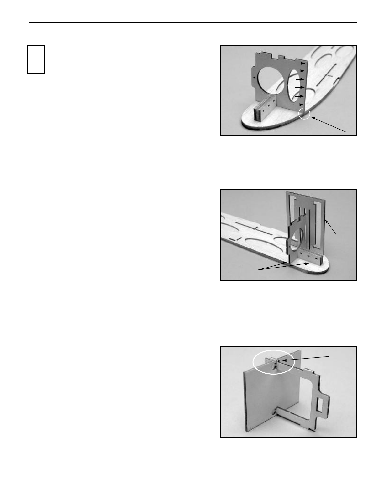
Align the fuselage side and doubler at the nose
When everything is perfectly aligned,
glue ovals first, then cutouts
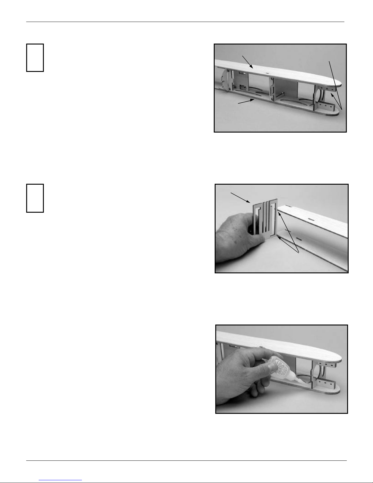
Slide the jigs towards one another to
align the doubler with the fuselage
side from top to bottom
The fixture will hold the two
parts in perfect alignment
Last 1/2”
1/32” Down
Leftfuselageside
Gluing the fuselage doublers in place...
When you’re satisfied with the alignment of the fuselage side and
doubler, glue them together with thin CA glue. First, put a drop of
glue every 1/2” or so around the perimeter of the oval cutouts in the
doubler. Then, put a drop of glue every 1/2” or so around the rest of
the cutouts, but don’t get carried way with the glue. When you insert
the formers and other parts into these cutouts you’ll be gluing them
again so you don’t need to get crazy with the glue at this stage.
When you’re done, run a bead of glue around the edge of the
doubler where it meets the fuselage side. Do the same for the other
doubler and fuselage side andDON’T MAKE TWO LEFT SIDES!!!
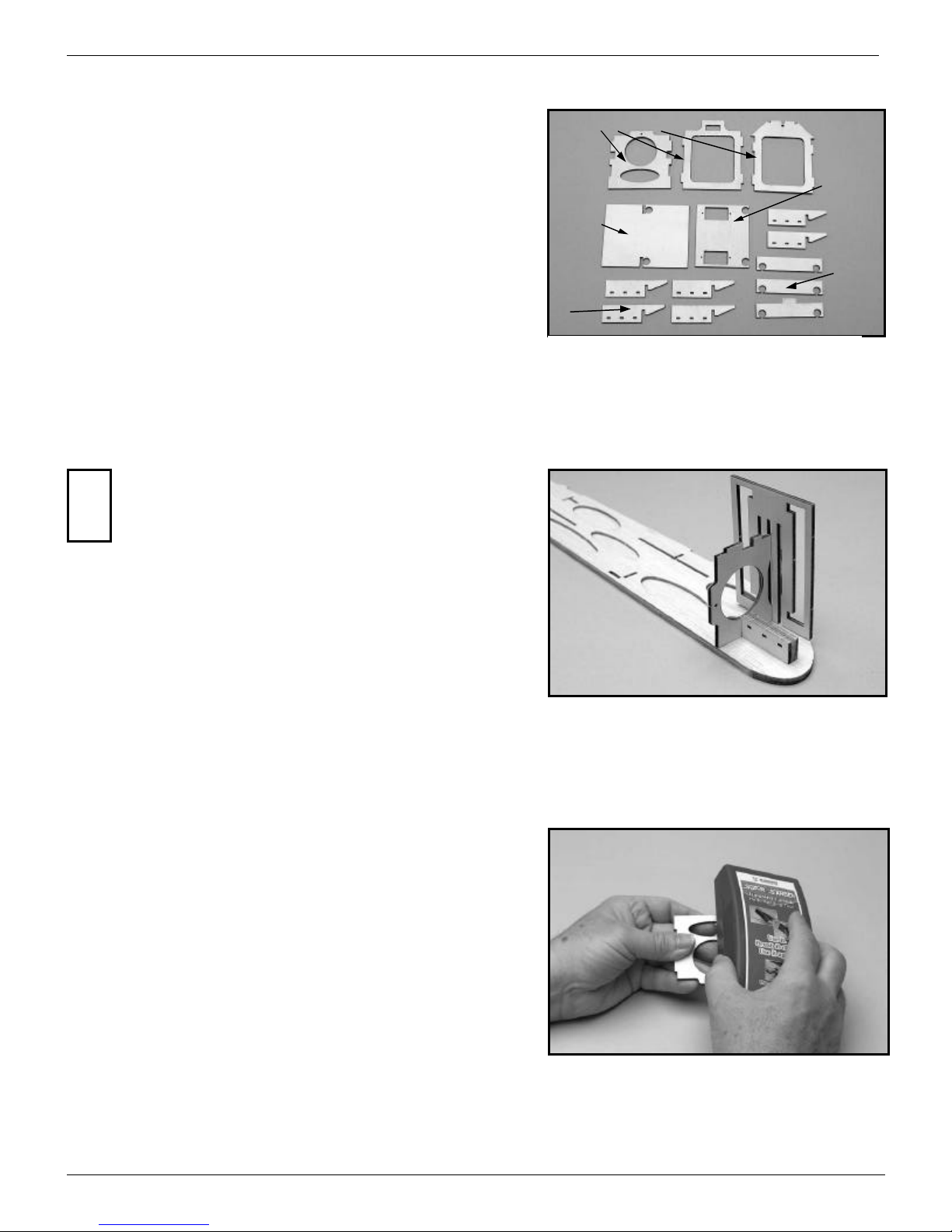
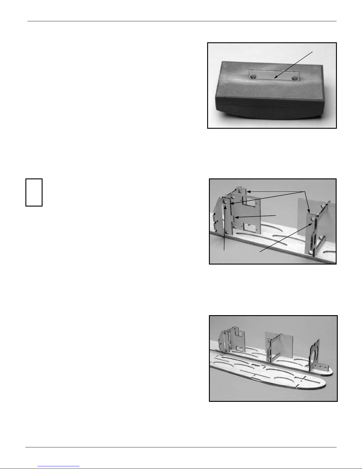
Aligning the fuselage doublers...
Now, for the fuselage doublers. Be careful, there’s a right and
a left! The left doubler has the cutout for the speed control’s
switch. To help you align the doubler with the fuselage side,
we’re included two “C” shaped plywood alignment fixtures.
First, use your eye and finger tips to align the two at the nose.
Then, slide on the front fixture from the nose and slide it rearward.
Then position the rear fixture and slide it forward. The fixtures will
only slide so far and then they will stop because the fuselage side and
doubler become larger in width than the cutout in the fixture. When
the fixtures can’t be slid any further towards one another, they will
have automatically put the doubler and fuselage side in perfect align-
ment with one another from top to bottom. The only thing you’ll have
to do is check to see that the two are still flush with one another at the
nose. If the two noses aren’t perfectly lined up with one another,
loosen the two fixtures, realign the two at their noses and then slide
the fixtures back on to realign the fuselage side and doubler from top
to bottom.
!
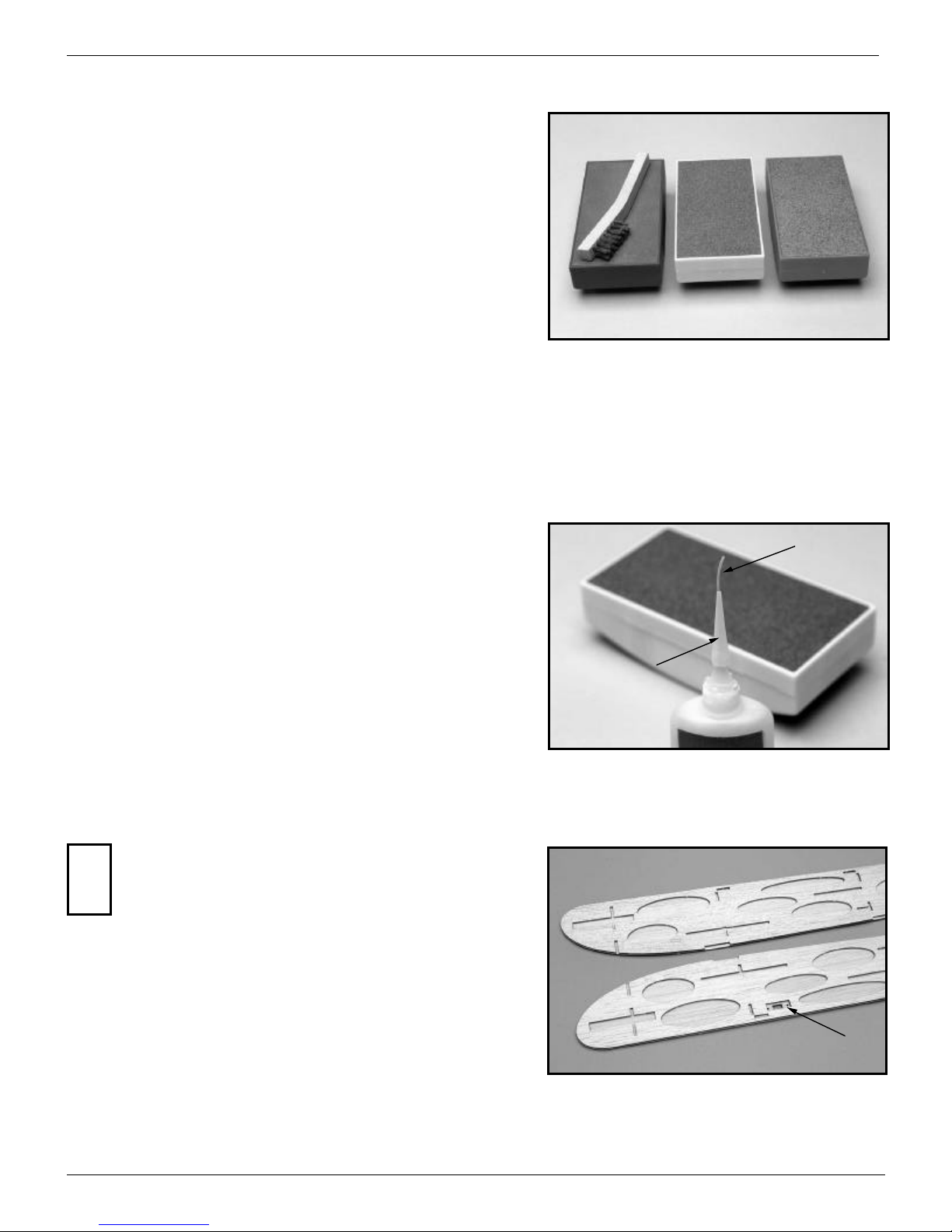
Chamfering the fuselage sides at the tail...
Before you start work on the doublers, you’ll have to chamfer
the rear inside edges of the fuselage sides so that when the fu-
selage sides are finally joined at the tail, the resulting fuselage
width will be 1/8”. To do this, you’ll only have to remove
1/32” of balsa in the last 1/2” of each fuselage side so that it ends up
being 1/16” thick. Make sure you’ve identified the right and left fu-
selage sides properly so that you’re sanding their inside edges and
not their outside edges!!! An easy way to make sure you don’t sand
past the 1/2” line is to lay a piece of masking tape along the line and
then sand up to the tape.
An easy way to know when you’re down to a thickness of 1/16”
is to use a scrap piece of 1/16” balsa as a feeler gauge. Keep compar-
ing the thickness of the aft edge of the fuselage with the 1/16” scrap.
When they are the same thickness, you’re done.
!
(See parts sheet #1)
AcroProtm Instruction Manual, Page 5
Find the parts...
The photo at the right illustrates the parts you’ll need for the next
steps so remove them from their sheets and give them a light sanding.
Trial fit your servos in the servo mounting tray and make any neces-
sary adjustments. The stock cutouts have been sized for MPI
MX50HP servos. Use a piece of wire to pop out any holes after first
cutting them free and trial fit the wing support tubes in the wing sup-
port mounting plates. If you do the same with the servo tray, you’ll
find that the holes are deliberately oversize so don’t panic.
Adjust the fit of the parts...
Use just a few gentle swipes of your sanding block at a very shal-
low angle on the edges of the parts where they are inserted into the
doubler to make them fit more easily. We are not talking about a lot
of sanding here. A few gentle swipes is all it will take. The parts
shouldn’t be loose, but they shouldn’t be tight either.
Don’t forget to do both edges because it will be more difficult to
sand these parts after one side has been glued in place.
Trial fit the right motor mount and firewall...
Each motor mount is made up of three pieces of plywood. The
top and bottom pieces should have the grain running the short
way across the motor mounting plate and the center piece
should have its grain running the long way down the plate.
Trial fit, but don’t glue, the three right motor mounting plates and
firewall into the right doubler. You’ll probably find that they are a
snug fit, but a little light sanding will fix that.
!
Formers F1, F2, and F3
Battery Pack
Tray
Servo Tray
Motor
Mounts
Wing
Support
Mounts
(See parts sheets #1, #2, and #3)
AcroProtm Instruction Manual, Page 6
Use the alignment jig...
We’ve given you a plywood alignmentfixture to keep everything
aligned properly. The fixture has three slots. The center slot is used
with plywood parts. The largest slot is for aligning the vertical
stabilizer after it’s covered and the narrowest slot is used with 3/32”
parts. The outer corners of the fixture are cut at exactly 90° which
will come in handy later.
With the firewall and motor mount firmly seated in their recesses
in the doubler, use the alignment fixture to make sure the firewall is
square with the doubler. Don’t glue anything! You’ll glue the fuse-
lage components together later after you’ve determined that every-
thing is in perfect alignment. We’ll tell you when to glue!
Alignment
Fixture
Tack glue
Battery pack mounting plate...
Before you install the second former, you’ll first insert the bat-
tery pack mounting plate through the hole in the center of the former
and rotate it into place. Slide the mounting plate down so that it’s po-
sitioned slightly below the top of the tab in the side of the former.
Trial fit it into the fuselage side to make sure the positioning of both
parts is perfect.
Chamfer the bottom forward edge of the firewall...
If you look closely, you’ll see that the forward, bottom edge of
the firewall needs to be sanded back at an angle because it
overlaps the fuselage side. Use your sanding block at an angle
and remove the small amount of overlapping material so that it
won’t interfere with the bottom sheeting when it’s glued in place.
!
AcroProtm Instruction Manual, Page 7
Third former...
Repeat the above step with the third former making sure it isn’t
snug or tight. Don’t glue anything!
Third former
Servo Mounting
Tray
Servo mounting tray...
Now is the time to trial fit your servos into the servo mounting
tray. We’ve already sized the plate forthe MPI MX50HP servo
that we highly recommend for the AcroPro, but it will be easy
for you to adjust the tray for other brands of servos. We’ve left
plenty of extra material in the plate so just open up the hole until it
fits the servos you’re going to use.
Dry fit and adjust the tray as necessary, but Don’t Glue It In
Place yet.
!
Second former...
Check the fit of the second former and battery mounting plate.
Again, use your sanding block to make sure you have a smooth fit
that isn’t snug or tight. Don’t glue anything!
Second former and battery
pack mounting plate
AcroProtm Instruction Manual, Page 8
The right side is done...
Here’s what the right fuselage side should look like at this point.
The right motor mount, firewall, battery pack mounting plate and
servo tray are in place.
Prepare the support plates...
The edge of the three wing support plates will probably have
some small protrusions where the tabs were left to keep the parts from
falling out of the plywood sheets. Take a few swipes with your sand-
ing block on the edge closest to the holes. Only move the piece in one
direction rather than back and forth as it will give you a straighter
edge. Don’t try to remove any material from this edge. You’ll only
trying to knock off any protrusions that would prevent the plates from
resting properly against the formers.
Don’t try to sand this edge. Only remove protrusions!
Right side
Leftside
Insert the support plates...
The three wing support plates should be dry fit and adjusted as
necessary. Notice that the upper rear support plate has a
“tab” protruding forward! Don’t glue them in place! Also,
notice that the holes are positioned closest to their respective
formers!
!Wing support plates
Holes close to formers!!!
Note Tab!
AcroProtm Instruction Manual, Page 9
Right angle jig
With one fuselage side flush up against
the right angle fixture, the other fuselage
side should be within 1/16” of thefixture.
If everything looks good, glue the
parts into the right fuselage side
Rightfuselageside
Leftfuselageside
Weight
Don’t Glue Anything Yet!!!
Don’t forget the Left motor mount!
Glue the parts into the right fuselage side...
OK, now you can use some glue! If the fuselage sides are close to
being square (within an 1/16” or so), go ahead and tack glue some of
the parts into the right fuselage side and then check the alignment
again.If the two are way off (1/8” or more), try to sand and adjust the
ends of the parts and the recesses in the doubler until you can align
the two fuselage sides with one another. If everything still looks good,
go ahead and glue the parts into the right fuselage side. This is an im-
portant step so make sure you get it right.
Check fuselage alignment...
Before gluing any parts together, use the right angle fixture to
check how closely the two fuselage sides line up at the tail. Put
the fixture flat on the building surface and see how close each
of the fuselage sides comes to the fixture.
If you were careful about lining up the doublers with the fuselage
sides and all of the formers were firmly seated in their recesses, the
fuselage sides should line up very closely with one another.
!
Trial fit the left fuselage side...
Following these instructions will assure a straight and true
fuselage without any twists.
Dry!!! fit the left fuselage side. Before you do, insert the
left motor mounting plates into the left fuselage side. Then,
starting at the nose, slip the firewall, battery pack support plate, sec-
ond former, wing support plates, servo tray, and third former into
their corresponding recesses in the left side doubler. Take your time.
Make sure that the parts are firmly seated in their recesses and that
nothing is preventing them from completely seating.
!
AcroProtm Instruction Manual, Page 10
Attach the left fuselage side...
Carefully turn the fuselage over. Make sure all of the parts are
still positioned properly and weight the fuselage down if necessary.
Check the alignment at the tail again with the right angle guide and if
everything looks good, go ahead and glue all of the parts into the left
fuselage side.
Float mounting plate Landing gear mounting plate
Gear mounting plates...
You’ll find that there are two recesses in the bottom of the fuse-
lage doublers for landing gear mounting plates. The forward set is
used for the landing gear and the rearward set is an attachment point
for floats if you ever choose to fly your AcroPro off of the water.
Even if you think you’ll never use floats, install the second mounting
plate anyway.
Assemble the landing gear mounting plates...
The first step in assembling the gear mounting plates is to
glue the two upper plates to the lower plate. You’ll find that
the upper plates are smaller.
To make it easier for you to align the three plates over one
another, we’ve cut a small notch in edge of each plate. If you line
these notches up with one another, you’ll find that the holes in the
plates are automatically lined up. The edge of the plates with the
notch should be flush with one another. When aligned properly, there
will be a recess formed on the other three sides of the assembled
mounting plate. Carefully align the upper and lower plates with one
another and glue them together.
!Upper plates
Lower plate
Notches
Align both plates along
this edge
Recessed
(See parts sheets #2 and #3)
AcroProtm Instruction Manual, Page 11
Dry fit before gluing the
mounting plate in place
Dry fit the gear plates...
The next step is probably best done with slow CA glue or ali-
phatic resin glue. But, before you glue anything, dry fit the two plates
in their recesses to see how they fit. They should just drop into place
snugly.
Glue the gear plates in place...
If you’re happy with the fit, run a bead of glue along the two
doubler recesses, the top of the former, and the face of the former.
Press the mounting gear plate firmly in place and let the glue dry. Do
this with both the front gear mounting plate and the rear float mount-
ing plate.
Final gluing...
When the glue is dry, use thin CA glue along any edges of the
two mounting plates that you can get at to make sure they are firmly
locked into place.
AcroProtm Instruction Manual, Page 12
Joining the fuselage sides at the tail...
If you’re lucky, the stiffness of your two fuselage sides will be
exactly the same and if you join them at the tail, they come together
centered. Forget about it. It isn’t going to happen. Wood is wood and
chances are the stiffness of the two sides will be different. No prob-
lem!
Before we start, I’m going to warn you that it’s very easy to
break loose the small piece of balsa that sticks out from each fuselage
side at the tail. Try to be careful and don’t bump this piece. If you do
and it cracks loose, don’t panic. Just line it back up and CA it back in
place. I know it’s easy to do because I’ve had to do it twice myself!
Insert a tail wheel mounting
plate into one lower slot in one
of the fuselage sides
Chances are that when you
bring the two fuselage sides
together, one will be longer
than the other because they
aren’t centered
Line up the two sides per-
fectly with each other and
the end of the tail wheel
mounting plate and tape
the sides together
Masking tape
Tail wheel mounting plates...
In the center of the third former located on the plywood parts
sheet #3, you’ll find three plywood pieces that look like arrow heads.
They are the mounting plates for your tail wheel assembly. Two look
like a barbed arrowhead and one looks like a regular point. The
barbed ones are the top and bottom tail wheel mounting plates. The
regular one fits between them. With your fuselage side turned upside
down, insert one of the barbed plates into the lower notch in the fuse-
lage side. Now, bring the two fuselage sides together at the tail and
see how they meet. Chances are they’ll look like the photograph
above and one will be longer than the other because they aren’t meet-
ing in the center.
Centering the tail...
In order to be centered, the two fuselage sides must be exactly
the same length and be flush with the end of the tail wheel mounting
plate. Have a friend hold the fuselage down or use some weights so
that it doesn’t move. Move the tail left or right until the two ends line
up with each other and the end of the mounting plate. When you think
you have it right,wrap a piece of masking tape around the tail to hold
everything in place.
(See parts sheet #3)
AcroProtm Instruction Manual, Page 13
Glue the fuselage sides together...
Now that the fuselage sides are centered and tack glued to each
other, run a bead of thin CA glue around the edges of the barbed tail
wheel mounting plate and down the joint where the two fuselage sides
meet.
Lower tail wheel mounting plate
Center tail wheel mounting plate.
Make sure the hole lines up with
the one below!
Double check the centering...
Now, turn the fuselage over, right side up, and lay it over the top
view of the fuselage on the plans. Take your time to line the front of
the fuselage up with the top view. Is your tail centered? It should lie
directly over the center line shown on the plans. If not, adjust it and
try again. Take your time as this is an important step. When you’re
happy with the result, tack glue the two fuselage sides together.
Insert the center tail wheel mounting plate...
Lay the center tail wheel mounting plate (the one without the
barb) on top of the first that you’ve already glued in place.
This second plate simply sits between the two fuselage sides.
Look down through the hole in the center plate and see if it
lines up with the first. Chances are that it won’t and you’ll have to
sand the two edges of the plate until it can slide back enough towards
the tail so that the two holes line up. When they do, glue the center
plate in place over the first plate.
!
Turn the fuselage
over and lay it over
the plans. The tail
should be centered.
If not, adjust it and
try again. When it’s
right, tack glue the
two sides together
AcroProtm Instruction Manual, Page 14
Glue the third plate in place...
You’re almost done. Lay the top barbed plate in place and if eve-
rything lines up, it should, glue it in place over the previous two tail
wheel mounting plates.
Finally, re-glue around the entire assembly including the joint at
which the two balsa fuselage sides meet.
The basic AcroPro fuselage assembly...
At this point you’ve completed the basic assembly of your Acro-
Pro’s fuselage. Most of the tough parts that will determine how well
your AcroPro will fly are behind you so pat yourself on your back and
let’s get the fuselage finished!
Bulkheads
Stringers Lower edge of bulkhead
Third tail wheel mounting plate
Assemble the top rear of the fuselage...
The top rear of the fuselage is constructed of three stringers and
four bulkheads. Two of the stringers are different from the third, but
we’ll get to that in a moment.
(See parts sheets #3, #4, and #11)
AcroProtm Instruction Manual, Page 15
Forward ends of the stringers
Rearward ends of the stringers
Center stringer
Long cutout in outer
stringers
Emery boards are
great for delicate
sanding
We’ve exaggerated the angle
here to make the point
Trim lower rear edges of bulkheads
where they meet the fuselage sides
Towards the fuselage rear
Identify the center stringer...
It’s easy to pick out the center stringer. If you look at the ends of
the stringers, you’ll see that two of them have long cutouts in one end.
Those are the outside stringers and the remaining one, with a short
cutout at both of its ends, is the center stringer.
Taper the edges of the bulkheads...
Because the fuselage tapers towards the rear, the rear edges of
the bulkheads have to be trimmed slightly so that they make
better contact with the fuselage sides. An emery board or a
scrap of plywood with a piece of sandpaper glued to it is a
great tool for this kind of delicate sanding.
Make sure you trim both edges of the bulkhead in the correct
direction (Don’t ask me how I know!). Don’t make one going for-
ward and one going rearward. Once you’ve decided which is the front
and which is the rear of each bulkhead, put a pencil mark on the front
side so that it will be easier to identify later on.
!
AcroProtm Instruction Manual, Page 16
Identify the front and rear of the center stringer...
Trying to figure out which end of the center stringer goes to-
wards the front and which end goes towards the rear is a little
tougher. Lay the three stringers down so that they are flush with each
other at one end and the center stringer is in the middle. Take a look
at the first set of notches in the stringers. Are all three notches in line
with one another, or is the notch in the center string out of alignment
with the other two? If you have the three stingers oriented properly,
all three notches will be lined up with each other.
Don’t panic trying to get this right. In the next step, nothing will
line up if you have it wrong and you’ll know immediately that you
have the center stringer turned the wrong way.
If properly oriented, with all three
forward ends of the stringers
aligned, the first row of notches will
be aligned too.
The center notch is out of
alignment with the other two
so the center stringer has to
be turned around
Out of alignment
DON’T reach for the glue...
The next steps will be done dry, without glue, initially to make
sure everything fits right. You won’t glue everything together until
the end.
AcroProtm Instruction Manual, Page 17
This line is perpendicular
to the stringers
The bulkhead is
leaning rearward
Take your time and dry fit the bulkheads
into the stringers one at a time
The fourth bulkhead will be flush
with the ends of the stringers
Insert the bulkheads one at a time...
Gently insert the bulkhead into the notches in the stringers.
You’ll notice that the bulkhead won’t go all the way down to the sur-
face of your table. We don’t want the bulkhead to show through your
covering material so the bulkhead stops short of the surface of the
stringers. Use the marks you made on the forward sides of the bulk-
heads as a guide to make sure the corners of the bulkheads that you
trimmed away by sanding them back are all facing rearward.
Be gentle with the stingers and try not to crack them. No, this is
one mistake I haven’t made yet, but if you do crack one, just use
some CA glue to fix it.
The final bulkhead...
Take your time and work each of the four bulkheads into place.
The fourth bulkhead, towards the tail, will end up being flush with the
ends of the stringers.
The bulkheads aren’t square to the stringers...
Before you insert the first bulkhead into the stingers, notice
that it doesn’t fit into the stringers at a 90 degree angle. In-
stead, it’s angled back some. The bulkhead will end up being
perpendicular to the fuselage, but it’s not perpendicular to the
stringers.
!
AcroProtm Instruction Manual, Page 18
If everything looks right, glue the
bulkheads into place
Install the stringer assembly...
While holding the rear of the stringer assembly up a little, slide
the ends of the stringers into the notches in the top of the third fuse-
lage former. Now, lower the stringer assembly at the rear and spread
the fuselage sides a little as each bulkhead drops into place. Make
sure that the stringers stay firmly seated in the notches in former #3.
Insert the forward ends of the
stringers into the notches in former
#3 first
When bulkhead #4 is inserted be-
tween the fuselage sides, the outer
stringers will come to rest on top of
the fuselage sides
The outer stringers rest on top of the fuselage sides...
Work your way to the rear and finally insert the fourth bulkhead
between the fuselage sides. You’ll find that the outer stringers will
come to rest on top of the fuselage sides.
Take a good look at the assembly. Are all of the little stops at the
outer corners of the bulkheads sitting firmly on the top of the fuselage
sides? Are the stringers still fully seated in former #3? If so, you can
go ahead and glue everything into place.
Glue the bulkheads to the stringers...
Double check the fit between the bulkheads and the stringers.
Are the bulkheads fully inserted into the notches? Are all the
tapers you sanded into the edges of the bulkheads facing to-
wards the rear of the fuselage??? If they are and everything is
sitting nice and flat on your building board, use thin CA glue to glue
all of the bulkheads to the stringers. You did remember to use waxed
paper under your work so that it doesn’t stick to the building board
didn’t you???
!

This manual suits for next models

1

Popular Toy manuals by other brands

GM-Racing MRX5 Street Bike instruction manual

GM-Racing

GM-Racing MRX5 Street Bike instruction manual

LGB 22062 manual

LGB

LGB 22062 manual

LEGO 41048 Friends Assembly guide

LEGO

LEGO 41048 Friends Assembly guide

Eduard Zoom Fw 190A-8/R11 1/32 manual

Eduard

Eduard Zoom Fw 190A-8/R11 1/32 manual

DTS DTS450 manual

DTS

DTS DTS450 manual

Fisher-Price Power Wheels FFR86 owner's manual

Fisher-Price

Fisher-Price Power Wheels FFR86 owner's manual

LEGO JUNGLE RESCUE BASE 41038 manual

LEGO

LEGO JUNGLE RESCUE BASE 41038 manual

Eduard Zoom F-4J Assembly instructions

Eduard

Eduard Zoom F-4J Assembly instructions

Uhlenbrock Elektronik DAISY user manual

Uhlenbrock Elektronik

Uhlenbrock Elektronik DAISY user manual

Fisher-Price Lil' Quad W6215 owner's manual

Fisher-Price

Fisher-Price Lil' Quad W6215 owner's manual

Seagull Models De Havilland DH-60M Moth 72" wingspan... Assembly manual

Seagull Models

Seagull Models De Havilland DH-60M Moth 72" wingspan... Assembly manual

Fisher-Price POWER WHEELS X6641 owner's manual

Fisher-Price

Fisher-Price POWER WHEELS X6641 owner's manual

Walkera HM 5#5 user manual

Walkera

Walkera HM 5#5 user manual

marklin 39183 user manual

marklin

marklin 39183 user manual

Eduard Blenheim Mk.IVF landing flaps quick start guide

Eduard

Eduard Blenheim Mk.IVF landing flaps quick start guide

Lionel 4-6-2 Pacific owner's manual

Lionel

Lionel 4-6-2 Pacific owner's manual

Sentera PHX Pilot operating handbook

Sentera

Sentera PHX Pilot operating handbook

K&W Model Airplanes De Havilland DH4 1916 Bomber Assembly manual

K&W Model Airplanes

K&W Model Airplanes De Havilland DH4 1916 Bomber Assembly manual

manuals.online logo
manuals.online logoBrands
  • About & Mission
  • Contact us
  • Privacy Policy
  • Terms and Conditions

Copyright 2025 Manuals.Online. All Rights Reserved.