ACS Marvair GAA1024A User manual

MODELS:
GAA1024A-GAA1030A-GAA1036A
GAA1042A-GAA1048A-GAA1060A
Installation & Operation Manual
11 EER Vertical Wall-Mount
Air Conditioners w/Gas Heat
IMPORTANT
This manual may include information for options and features which may not be
included on the unit being installed. Refer to the unit data label or Model Identication
to determine which features and options this unit is equipped with.
INSTALLER: Afx the instructions on the inside of the building adjacent to the thermostat.
END USER: Retain this manual for future reference.
Air Conditioner Product Manual
Vertical Wall-Mount Air Conditioners
with Gas Heat & Front Control Box Panel
Manufactured By:
Marvair, An AirX Climate Solutions Brand
P.O. Box 400 • Cordele, Georgia 31010 • 156 Seedling Drive • Cordele, Georgia 31015
(229) 273-3636 • Fax (229) 273-5154
E-mail: marvairsales@airxcs.com • Internet: www.Marvair.com
The most current version of this manual can be found at www.Marvair.com.
Marvair GAA A/C w/Gas Heat I&O Manual 06/2023 Rev.5

2
Marvair GAA A/C w/Gas Heat I&O Manual
06/2023 Rev.5
How To Use This Manual
This manual is intended to be a guide to Marvair GAA family of vertical air conditioners with gas heat. It contains
installation, troubleshooting, maintenance, warranty, and application information. The information contained in this
manual is to be used by the installer as a guide only. This manual does not supersede or circumvent any applicable
national or local codes.
If you are installing the GAA unit, rst read Chapter 1 and scan the entire manual before beginning the installation as
described in Chapter 2. Chapter 1 contains general, descriptive information and provides an overview which can speed
up the installation process and simplify troubleshooting.
If a malfunction occurs, follow this troubleshooting sequence:
1. Make sure you understand how the GAA unit works (Chapters 1 & 3).
2. Identify and correct installation errors (Chapter 2).
3. Refer to the troubleshooting information in Chapter 4.
If you are still unable to correct the problem, contact the Factory at 1-800-841-7854 for additional assistance.
Please read the following “Important Safety Precautions” before beginning any work.
Important Safety Precautions
1. USE CARE when LIFTING or TRANSPORTING equipment.
2. TRANSPORT the UNIT UPRIGHT. Laying it down on its side may cause oil to leave the compressor and breakage
or damage to other components.
3. TURN ELECTRICAL POWER OFF AT THE breaker or fuse box BEFORE installing or working on the equipment.
LINE VOLTAGES ARE HAZARDOUS or LETHAL.
4. OBSERVE and COMPLY with ALL applicable PLUMBING, ELECTRICAL, and BUILDING CODES and ordinances.
5. SERVICE may be performed ONLY by QUALIFIED and EXPERIENCED PERSONS.
* Wear safety goggles when servicing the refrigeration circuit
* Beware of hot surfaces on refrigerant circuit components
* Beware of sharp edges on sheet metal components
* Use care when recovering or adding refrigerant
6. Use COMMON SENSE - BE SAFETY-CONSCIOUS
This is the safety alert symbol . When you see this symbol on the GAA unit and in the instruction
manuals be alert to the potential for personal injury. Understand the signal word DANGER, WARNING,
CAUTION and IMPORTANT. These words are used to identify levels of the seriousness of the hazard.
DANGER Failure to comply will result in death or severe personal injury and/or property damage.
WARNING Failure to comply could result in death or severe personal injury and/or property damage.
CAUTION Failure to comply could result in minor personal injury and/or property damage.
IMPORTANT Used to point out helpful suggestions that will result in improved installation, reliability or
operation.
© 06/2023 Marvair, An AirX Climate Solutions Brand
SPECIFICATIONS SUBJECT TO CHANGE WITHOUT NOTICE.

3
Marvair GAA A/C w/Gas Heat I&O Manual
06/2023 Rev.5
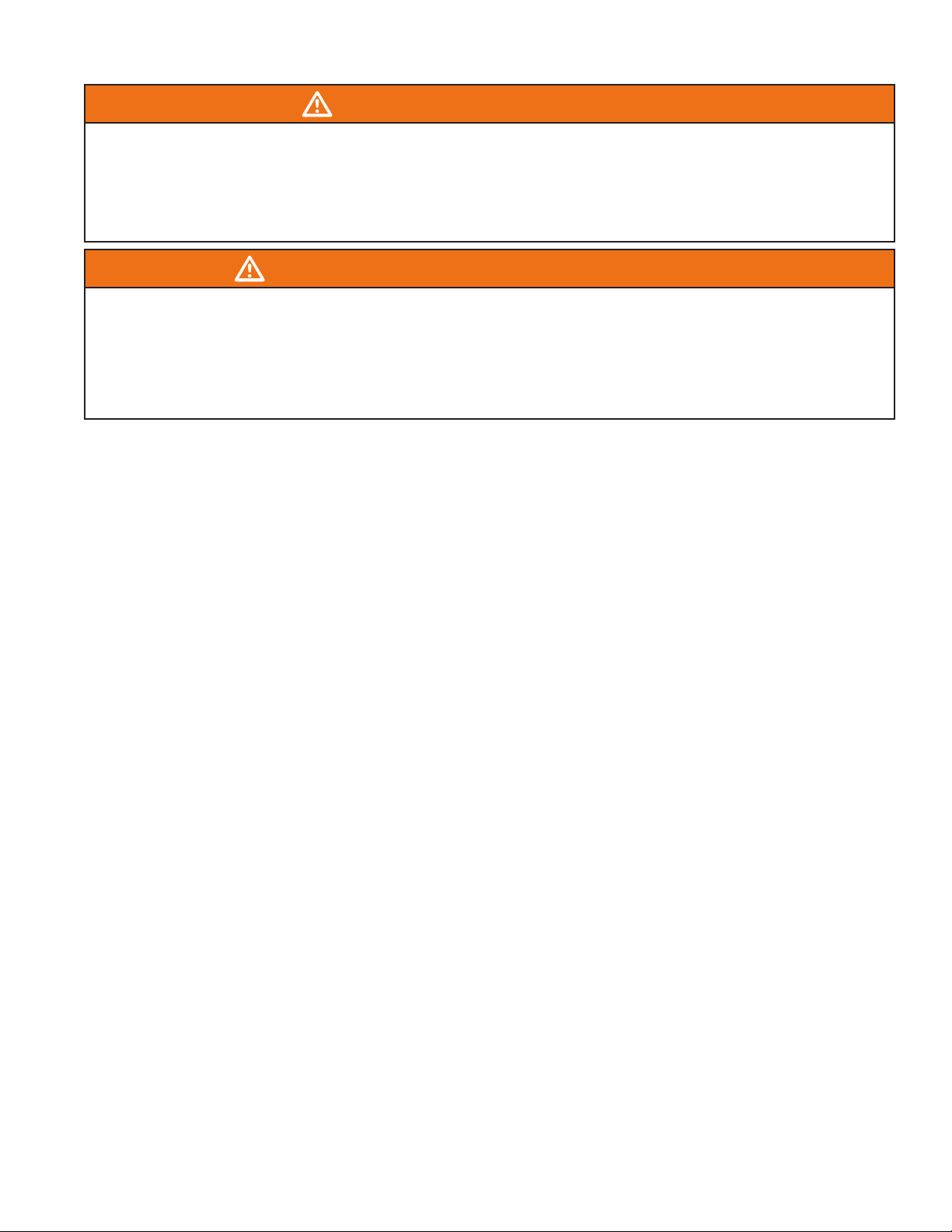
WARNING - SAFETY REQUIREMENTS
• If the information in these instructions are not followed exactly, a re, carbon monoxide poisoning or explosion may result causing
property damage, personal injury or loss of life.
• Read all instructions carefully prior to beginning the installation. Do not begin installation if you do not understand any of the
instructions.
• Improper installation, adjustment, alteration, service or maintenance can cause property damage, personal injury or loss of life.
• Installation and service must be performed by a qualied installer, service agency or the gas supplier in accordance with these
instructions and in compliance with all codes and requirements of authorities having jurisdiction.
• Follow all safety codes.
AVERTISSEMENT - EXIGENCES POUR LA SÉCURITÉ
• Si les informations contenues dans ces instructions ne sont pas suivies exactement, ipeut en résulter un empoisonnement au
monoxyde de carbone ou une explosion, causant dommages, blessure ou mort.
• Lisez soigneusement toutes les instructions avant de commencer l'installation. Ne la commencez pas si vous n'avez pas assimilé
toutes ces instructions.
• Une mauvaise exécution d'installation, réglage, altération, intervention ou entretien peut causer dégâts matériels et dommages
corporels ou même mort.
• Installation et interventions doivent être effectuées par un installateur ou une agence de dépannage qualiés, ou par le fournisseur
de gaz en conformité avec toutes les normes et exigences des autorités ayant juridiction en la matière.
• Respectez toutes les normes de sécurité.
Table of Contents
Chapter 1 - Description & Specications
1.1 General Description ...............................................................................................................................5
1.2 Model Identication ..............................................................................................................................6
1.3 Serial Number Date Code ......................................................................................................................6
1.4 Cooling Mode ......................................................................................................................................6
1.5 Sequence of Operation - Heating Mode ...............................................................................................7
1.6 Ventilation Options ..............................................................................................................................8
1.7 Economizer Operation – Cooling Cycle (unit with economizer only) ................................................9
Chapter 2 Electronic Control Board
2.1 Introduction............................................................................................................................................10
2.2 Installation and Replacement .................................................................................................................11
2.3 PCB Details and Information.................................................................................................................11
2.4 Operation................................................................................................................................................15
2.5 Sequence of Operation ...........................................................................................................................15
Chapter 3 – Safe Installation Requirements
3.1 Safety Rules .......................................................................................................................................28
Chapter 4 – Installation
4.1 Location and Clearances ....................................................................................................................30
4.2 Installation Requirements ..................................................................................................................31
4.3 Dimensional Data ...............................................................................................................................33
4.4 Equipment Inspection ........................................................................................................................36
4.5 Clearances ..........................................................................................................................................36
4.6 Installation Materials .........................................................................................................................37
4.7 Porting and Duct Work ......................................................................................................................38
4.8 General Information ...........................................................................................................................38
4.9 Wall Openings ....................................................................................................................................38
4.10 Minimum Airow Requirements .......................................................................................................38
4.11 Ducting ...............................................................................................................................................39
4.12 Hanging the Unit on the Wall ............................................................................................................39
4.13 Gas Supply and Piping .......................................................................................................................40
4.14 Gas Supply Requirements ..................................................................................................................40
4.15 Gas Piping Requirements ...................................................................................................................40
4.16 Electrical Connections .........................................................................................................................43
4.17 Venting of the Furnace .......................................................................................................................47
4.18 Installation of the Vent Hood. ............................................................................................................47

4
Marvair GAA A/C w/Gas Heat I&O Manual
06/2023 Rev.5
Chapter 5 – Checks and Adjustments
5.1 Gas Supply Pressure ..........................................................................................................................48
5.2 Manifold Gas Pressure Adjustment ...................................................................................................48
5.3 Natural Gas Input Rating Check ........................................................................................................50
5.4 Orice Sizing .....................................................................................................................................50
5.5 LP Gas Conversion ............................................................................................................................51
5.6 High Altitude Installations .................................................................................................................53
5.7 Changing Orices ..............................................................................................................................54
5.8 Main Burner Flame Check .................................................................................................................55
5.9 Temperature Rise Range ....................................................................................................................55
Chapter 6 – Start-up
6.1 Cooling Cycle ....................................................................................................................................56
6.2 Heating Cycle .....................................................................................................................................56
6.3 Start-Up Checklist................................................................................................................................58
Chapter 7 – Maintenance
7.1 Maintenance – Burner and Vent Outlet. .............................................................................................59
7.2 Air Filter .............................................................................................................................................59
7.3 Indoor Coil .........................................................................................................................................59
7.4 Outdoor Coil ......................................................................................................................................59
7.5 Cabinet ...............................................................................................................................................59
7.6 Drains .................................................................................................................................................60
7.7 Lubrication .........................................................................................................................................60
7.8 Burner Flame .....................................................................................................................................60
7.9 Burner ................................................................................................................................................61
7.10 Combustion Air Inlet and Outlet ........................................................................................................61
7.11 Venting of the Furnace .......................................................................................................................61
7.12 Clearances ..........................................................................................................................................61
Chapter 8 – Parts List..................................................................................................................................62
Chapter 9 – WarrantyPolicy
9.1 Marvair Limited Product Warranty......................................................................................................64
Illustrations
Figure 1. Enthalpy Sensor & Temperature Control Points ........................................................................20
Figure 2. Dry Bulb Sensor..........................................................................................................................21
Figure 3a. Models GAA1024A/GAA1030A/GAA1036A Dimensional Data.............................................33
Figure 3b. Models GAA1042A/GAA1048A Dimensional Data..................................................................34
Figure 3c. Models GAA1060A Dimensional Data ......................................................................................35
Figure 4. Mounting the Unit on a Wall.......................................................................................................39
Figure 5a. Typical Electrical Schematic - 1Ø Power Supply.......................................................................45
Figure 5b. Typical Electrical Schematic - 3Ø Power Supply.......................................................................46
Figure 6. Vent Hood Installation ................................................................................................................47
Figure 7. Gas Valve Manifold Pressure Tap ...............................................................................................49
Figure 8. Gas Valve Protective Cover ........................................................................................................49
Figure 9. Gas Valve Manifold Pressure Tap ...............................................................................................52
Figure 10. Gas Valve Protective Cover ........................................................................................................53
Figure 11. Burner Flame ..............................................................................................................................55
Figure 12. Gas Control Valve Switch...........................................................................................................56
Figure 13. Burner Flame ..............................................................................................................................60

5
Marvair GAA A/C w/Gas Heat I&O Manual
06/2023 Rev.5
Tables
Table 1. Minimum Clearances from Unprotected Combustible Material and For Service .....................30
Table 2. Electrical Rating Designations...................................................................................................32
Table 3. Minimum Clearances from Unprotected Combustible Material and For Service .....................36
Table 4. Gas Pressures..............................................................................................................................40
Table 5. Natural Gas Input Rating............................................................................................................50
Table 6. Altitude/Orice Sizing ...............................................................................................................50
Table 7. Altitude/Orice Sizing ...............................................................................................................54
Table 8. Temperature Rise Range ............................................................................................................55
Chapter 1 Description and Specifications
1.1 General Description
The Marvair® GAA line of air conditioners with gas heat are high efciency vertical wall mounted units
that provide cooling and economical gas heating. In addition, various ventilation packages are factory
installed for a variety of applications. Nominal cooling capacities are 24,000 BTUH, 30,000 BTUH,
36,000 BTUH, 42,000 BTUH, 48,000 BTUH and 60,000 BTUH with EER’s of 11.00. Models GAA1024,
GAA1030A & GAA1036A are factory set up for natural gas with nominal heating capacities of 45,000
BTUH, 67,5000 BTUH and 90,000 BTUH. Models GAA1042A, GAA1048A and GAA1060A are factory
set up for natural gas with nominal heating capacities are 75,000 BTUH, 100,000 BTUH and 125,000
BTUH. The units are easily eld convertible to propane.
Marvair GAA air conditioners with gas heat are designed for easy installation. All units have built-in
side mounting anges and are shipped with a bottom support bracket. All units are factory wired and
charged. Service ports have been provided for eld service, if required. All internal wiring is complete.
A wide selection of fresh air ventilation packages, all factory installed and tested to insure op-
timum performance, are available to meet various installation requirements. For school class-
rooms, models are available to comply with the ASHRAE 62-1999 standard, “Ventilation for
Acceptable Indoor Air”. The exclusive GreenWheel®energy recovery unit (ERV), provides fresh
air while removing both sensible and latent heat form the incoming air stream.
All Marvair air conditioners with gas heat furnaces are tested in accordance with UL standard 1995 and
listed by ETL. Performance and Efciency Ratings are in accordance with the Air Conditioning and
Refrigeration Institute ( ARI ) standard 390.

6
Marvair GAA A/C w/Gas Heat I&O Manual
06/2023 Rev.5
1.2 Model Identification
Example G A A 1 0 3 6 A A 0 9 0 C G + + + 1 D A + A 1 1 + + + + + +
Position 1234567891011 12 13 14 15 16 17 18 19 20 21 22 23 24 25 26 27 28 29 30
1Unit Designation/Family G = Marvair Wall Mount w/Gas Heat
2Energy Efciency Ratio (EER) A = 11
3Refrigerant Type A = R-410a
4Compressor Type/Quantity 1 = Single
5Unit Capacity/Nominal
Cooling (BTUH)
024 = 24,000 042 = 42,000
030 = 30,000 048 = 48,000
036 = 36,000 060 = 60,000
6
7
8System Type A = Air Conditioner
9Power Supply
(Volts-Hz-Phase)
A= 208/230-60-1
C= 208/230-60-3
D= 460-60-3
10 Heat Designation
@ Rated Voltage
KW = Kilowatt
045 = 45,000 BTUH 090 = 90,000 BTUH
067 = 67,500 BTUH 100 = 100,000 BTUH
075 = 75,000 BTUH 125 = 125,000 BTUH
11
12
13 Ventilation
Conguration
C = Economizer
D = Motorized Damper w/Pressure Relief
E = Motorized Damper w/Pressure Relief &
Independent Motorized Damper Control
F = No Free Cooling, 100% Emergency
Ventilation Only w/Independent Control
H = GreenWheel N = Barometric Damper
w/15% OSA
N = Barometric Damper w/15% OSA
14 Dehumidication
G = Hot Gas Reheat
H = Hot Gas Reheat w/Humidity Control
J = Hot Gas Reheat w/Return Air Limit
K = Hot Gas Reheat w/Humidity Control &
Return Air Limit
M = Modulating Hot Gas Reheat
N = Modulating Hot Gas Reheat w/Humidity
Control
+ = None
15 Controls
A = Power Fail Alarm w/Additional Lockouts
C = 24V EMS Relay Kit
D = 24V EMS Relay Kit
w/Factory Installed T-Stat
E = Factory Installed T-Stat
+ = None
16 Operating Condition
A = Evaporator Freeze Sensor (EFS)
N = Hard Start
P = Hard Start w/Low Ambient & CCH
Q = Hard Start w/Low Ambient &
Fan Cycle Control (FCC)
R = Crank Case Heater (CCH)
T = Hard Start w/EFS
V = Hard Start w/Low Ambient &
CCH & EFS
W = Low Ambient w/CCH
Y = Low Ambient w/CCH & FCC
Z = Low Ambient w/CCH & EFS
1 = Low Ambient w/FCC
2 = Low Ambient w/FCC & EFS
+ = None
17 Indoor Air Quality
Features
D = Dry Bulb Sensor
E = Dry Bulb Sensor w/Dirty Filter
G = Dirty Filter Sensor
+ = None
18 Air Flow 1 = Top Supply/Bottom Return
19 Compressor
Location
D = Left Hand
E = Right Hand
20 Filter Option
A = 2” Pleated (MERV 8, AC/HP-C)
C = 2” Charcoal
D = MERV 11 High Filtration Package
E = MERV 13 High Filtration Package
F = Filter Access Through Return Air Grille
W = Aluminum Washable
+ = None
21 Corrosion
Protection
A = Condenser Coil Only
C = Evaporator Coil Only
D = Both Coils Condenser & Evaporator
E = All Coils Cond/Evap/Reheat
F = Coat All
K = Coastal Package
+ = None
$ = Special
22 Engineering
Revision Level A1
23
24 Cabinet Color
1 = Marvair Beige
2 = Gray
3 = Carlsbad Canyon
4 = White
5 = Stainless Steel Exterior
6 = Dark Bronze
8 = Mesa Tan
9 = Pebble Gray
A = Stainless Steel - Unit
$ = Custom Color (Powder Coat)
25 Sound Attenuation 2 = Compressor Blanket
+ = None
26 Security Option A = Lockable Access Plate/Tamper Proof
+ = None
27 Fastener/Drain Pan
Option
A = Stainless Steel Fasteners
C = Stainless Steel Drain Pan
D = Stainless Steel Fasteners & Drain Pan
+ = None
28 Unused + = None
$ = Special
29 Unused + = None
$ = Special
30 Special Variation
+ = None
$ = Special Conguration Not Covered by
Model Nomenclature
Note: Not all options are available with all congurations. Contact
your Marvair sales representative for conguration details and
feature compatibility.
1.3 Serial Number Date Code
20 = 2020 01 = January 05 = May 09 = September
21 = 2021 02 = February 06 = June 10= October
22 = 2022 03= March 07 = July 11 = November
23 = 2023 04 = April 08 = August 12 = December
1.4 Cooling Mode
Marvair GAA air conditioners with gas heat use R410A refrigerant in a conventional vapor-compression
refrigeration cycle to transfer heat from air in an enclosed space to the outside. A double blower assembly
blows indoor air across the evaporator. Cold liquid refrigerant passing through the evaporator is boiled
into gas by heat removed from the air. The warmed refrigerant gas enters the compressor where its
temperature and pressure are increased. The hot refrigerant gas condenses to liquid as heat is transferred
to outdoor air drawn across the condenser by the condenser fan. Liquid refrigerant is metered into the
evaporator through capillary tubes to repeat the cycle.

7
Marvair GAA A/C w/Gas Heat I&O Manual
06/2023 Rev.5
1.5 Sequence of Operation - Heating Mode
1. On a call for heat, two stage thermostat contact( s ) close, providing 24 VAC to “4” terminal on
the ignition control.
2. Draft inducer is energized at high speed ( B-W leads ) at line voltage.
3. Air Pressure Switch ( APS ) closes, initiating 30 second prepurge.
4. At end of 30 second prepurge period, Spark & Gas Valve are energized for up to 5 second
ignition trial. Gas valve will open in either low or high re position, depending upon the heat
requirements and contact closure in the thermostat.
5. Burners ignite and carryover.
6. Flame is detected by ame sensor and control operates in steady state heating position.
7. The two stage thermostat powers the low re contact continuously on a call for heat and will
close the high re contact if necessary to meet heat requirements. Unit continues in operation
in either low or high re until the thermostat set point is reached.
8. Low re contact in thermostat opens, interrupting power to “4” terminal on control and closing
the gas valve.
9. The Draft inducer continues to run for a 60 second post purge period.
10. The control system is capable of three retrials if the above sequence is interrupted at any point.
If the above sequence does not occur then:
11. If ignition is not achieved with in 5 seconds, the gas valve is shut off, the inducer keeps running for
an inter purge period of 60 seconds and additional trials follow the specied sequence. If all 3 trials
for ignition have occurred without proper ignition and ame detection, the control is locked out.
12. Control may be brought out of lock out by a. turning the thermostat to OFF for a minimum of
5 seconds and then ON, or b. turning the disconnect to OFF for a minimum of 5 seconds and
then ON. Control will automatically also attempt another ignition sequence one hour after a
lockout occurrence.
13. If ame is lost once it has been established, the control will shut off the gas supply within .8
seconds and enter the interpurge period. Control will initiate up to 3 additional trials per normal
sequence of operation. ( To restart, refer to item 12 ).
14. If ame sensor indicates presence of a ame during the purge period when no ame is present,
the inducer will remain energized, but the gas valve will not be energized until the cause of the
false ame is removed.
15. If the air pressure switch ( APS ) is closed when the inducer is energized or does not close after
the inducer is energized, the control will wait one minute for the air switch to open or close and
then lock out. ( To restart, refer to item 12 ).
16. If the control detects power to the gas valve when the it should be off or no power when it
should be on, the control will go into lockout with all outputs off. ( To restart, refer to item 12 ).

8
Marvair GAA A/C w/Gas Heat I&O Manual
06/2023 Rev.5
The gas heat and air conditioner has a LED indicator that shows operating status and simplies service
by ashing fault codes.
On-Steady Control Operation Normal
1 Flash Open Air pressure switch, limit switch or ame rollout switch
2 Flashes Pressure switch stuck closed
3 Flashes Ignition / ame sensor failure
4 Flashes Repeated ame loss
5 Flashes Internal control fault
6 Flashes Repeated pressure switch losses
LED Flash Code Key
1.6 Ventilation Options
Configuration “C”: Up to 100% Modulating Economizer
The economizer reduces the cost of air conditioning by using outside air when acceptable to cool the
room (Free Cooling). The factory installed Marvair® economizer has integral pressure relief.
Control Board Logic: Upon a “Call for Cooling”, the economizer control board calculates whether the
HVAC operates in economizer mode or mechanical cooling mode based on outdoor temperature (dry
bulb) or temperature/humidity (enthalpy). When outdoor conditions are favorable for economizer cooling
, the damper drives open and modulates to maintain a 55ºF mixed air temperature through the supply
grille. When outdoor conditions are not favorable for economizer cooling, the economizer damper remains
closed, and the HVAC unit will operate in mechanical cooling mode.
Features Designed for Telecommunication applications: Hydrogen Fault Input: When 24VAC is applied
to the H_FLT input, the economizer board forces the damper to open 100% for emergency ventilation.
The compressor does not operate during Hydrogen Fault/Emergency Ventilation. Thermostat must provide
the fan “G” signal to HVAC to activate the indoor blower.
Forced Mechanical Cooling: When 24VAC is applied to the FC input of the economizer board, the
economizer damper is forced closed, and the HVAC will operate in mechanical cooling mode. This is
considered as economizer override in the event economizer cooling is not sufficient for the heat load.
Thermostat must provide the fan “G” signal to HVAC to activate the indoor blower.
Economizer Status: The economizer board has contacts that when used with the Marvair CommStat 4
Telecom HVAC Controller, change state to provide feedback to the CommStat 4 to indicate when the
HVAC is in economizer mode verses mechanical cooling mode. This feedback allows the CommStat 4
to initiate the forced cooling feature to override economizer cooling and force mechanical cooling.
When used with minimum position potentiometer (optional), the Marvair® economizer can meet require-
ments of ASHRAE Std. 62.
Configuration “D”: Two-Position Motorized Fresh Air Damper w/Pressure Relief Ventilation
Control Board Logic: The 92589 control board allows the position of the “D” damper to be set for desired
outside air intake from fully closed to fully open. Setting 15 of the control board configuration menu
allows the user to set the position from 20 (2VDC / Closed) to 100 (10VDC 100% open). The damper
position can be adjusted in 1VDC increments to any position from closed to 100% open as required.
Operation: Anytime the indoor blower operates, the damper drives open to the position selected in the
control board configuration menu setting 15. When the indoor blower stops operation the motorized
damper spring returns to the fully closed position.
Note: This circuit does not interrupt the compressor or heater operation.

9
Marvair GAA A/C w/Gas Heat I&O Manual
06/2023 Rev.5
Configuration “E”: Two-Position Motorized Fresh Air Damper w/Pressure Relief Ventilation &
Independent Control
Control Board/Factory Installed Relay Logic: The 92589 control board allows the position of the “E”
damper to be set for desired outside air intake from fully closed to fully open. Setting 15 of the control
board configuration menu allows the user to set the position from 20 (2VDC / Closed) to 100 (10VDC
100% open). The damper position can be adjusted in 1VDC increments to any position from closed to
100% open as required.
Operation: Upon a “Call for Motorized damper” via a 24V signal from an external user-installed device,
the motorized damper opens to the position selected in the control board configuration menu setting 15
and the indoor blower operates. A 24VAC signal {sourced from LVTB 24VAC “R” and supplied through
a user-provided Normally Open (NO) contact} activates (opens) the Motorized Damper and connected
Relief Damper. When the 24VAC signal is removed, the motorized damper spring returns to the fully
closed position and the indoor blower stops operation. The motorized damper Does NOT open when
there is a call for the indoor fan (G).
Note: This circuit does not interrupt the compressor or heater operation.
Configuration “F”: No Free Cooling, 100%- Damper Opening, Emergency Ventilation Only w/
Pressure Relief and Independent Control
Factory Installed Relay Logic: Upon a “Call for emergency ventilation”, from an external user-provided
device; the motorized damper opens to 100% open position and the indoor blower is forced to operate.
During “Emergency Ventilation mode”, the compressor and heater do not operate. The relay has a wire
lead extended for the installer to connect their emergency ventilation control signal.
Note: This circuit interrupts the compressor and heater operation and forces the indoor blower and damper
to operate during emergency ventilation mode.
Configuration “N”: Manual Fresh Air Damper (Standard)
Barometric damper capable of up to 15% of the air conditioner’s total rated airflow of outside air; field
adjustable, no pressure relief.
1.7 Economizer Operation – Cooling Cycle (Marvair GAA unit with Economizer only)
The economizer is a regulated damper system with controls. The damper regulates the circulation of outside
air into the enclosure ( when the outdoor air conditions are suitable ) to reduce the need for mechanical
cooling, save energy, and extend compressor life.
Depending upon the options selected, the damper responds to either enthalpy or dry bulb temperature of
the outdoor air. On a call for cooling from a space thermostat, it operates as follows:
When the enthalpy of the outdoor air is below the set point, the outdoor air damper is proportioned open
( and return air damper is proportioned closed ) to maintain between 50o F and 56o F at the mixed / discharge
air sensor.
When the enthalpy of the outdoor air is above the set point, the outdoor air damper closes to its minimum
position. A call for cooling from the space thermostat brings on mechanical cooling.
An optional built-in adjustable minimum position potentiometer, p / n 70012, controls the amount of
outdoor air admitted to meet minimum ventilation requirements.

10
Marvair GAA A/C w/Gas Heat I&O Manual
06/2023 Rev.5
Chapter 2 Electronic Control Board
2.1 Introduction
WARNING
Failure to observe the instructions contained in this document may result in personal injury and/or property
damage and may void the warranty. Read this manual before installing, replacing or using this product.
Marvair’s proprietary Printed Circuit Board (PCB) sets the standard for the industry in flexibility, reliability and
performance. This UL certified component is engineered to optimize Heating, Cooling and Dehumidification
operation while communicating valuable information to the end user. Special features include 2-Stage operation
with varying speed control to optimize latent and sensible capacity, built in remote communication (Modbus)
for monitoring and/or control, optimized head pressure control and configurable menu options for various
operations and control. The Marvair PCB comes equipped with seven segment display to annunciate faults,
which drastically reduces troubleshooting time and system downtime. Lockout contacts are also provided along
with the alarms being transferred via Modbus.
This chapter provides the necessary information for installing and operating the Marvair PCB. The diagram
below identifies the inputs, outputs and connections for the Marvair PCB. See I/O table.
1
16
17
18
19
20
21
22
23
2 3 4 5 6 7
121315 14
9 10
11
8

11
Marvair GAA A/C w/Gas Heat I&O Manual
06/2023 Rev.5
Item Description
1Economizer Actuator Output 2-10 VDC
2Outdoor Motor Control Output 0-10 VDC or PWM
3Indoor Motor Control Output 0-10 VDC or PWM
4Enthalpy Sensor Signal Input 4-20mA
5Outdoor Sensor Signal 10K NTC (Heat Pumps) / Dry Bulb Sensor Signal Input 10K NTC
(Systems Equipped with Dry Bulb Economizer)
6Supply Air Sensor Signal Input 10K NTC (Systems Equipped with Economizer)
7Defrost Sensor Signal Input 10k NTC (Heat Pumps Only)
8Head Pressure Control Sensor Signal 10k NTC (ECM Motors)
9Control Board Menu/Fault Display
10 Menu/Up/Down Selection Buttons
11 Modbus RJ11 Communications Ports
12 Low Pressure / Freeze Sensor Signal Input 10k NTC
13 High Pressure Switch Input (Normally Closed)
14 Thermostat Inputs/Alarm And Status Terminals
15 24 VAC To Power Board (18 VAC To 30 VAC)
16 Indoor Blower Output 24 VAC (PSC Motors)
17 Reheat Output 24 VAC (Hot Gas Or Electric Reheat Dehumidication)
18 Reversing Valve Output 24 VAC (Heat Pumps Only)
19 Electric Heat Output 24 VAC
20 Outdoor Fan Output 24 VAC (PSC Motors)
21 Compressor 1/1st Stage Output 24 VAC (Single Stage Compressor)
22 Compressor 2/2nd Stage Output 24 VAC (Dual Compressor System 2nd Compressor)
(Single Compressor 2nd Stage)
23 Control Board Power Indicator LED
2.2 Installation and Replacement
The PCB is factory installed. To install a replacement PCB, use the six mounting holes along with the appropriate
screw size to rmly secure the board to the control box. After this is achieved, follow the wiring diagram and
menu conguration for the respective system for appropriate operation. Ensure that the terminals used do not
make any unwanted electrical connection (via strands etc.) with any other terminals. Please allow a 1” creepage
distance between the board and all other adjacent electrical components.
2.3 PCB Details and Information
The PCB is equipped with an on board seven-segment display (Item #9) for
conguring various settings and displaying faults. During normal operation the
display remains off unless the conguration menu is accessed or a fault has occurred.
Faults will be annunciated on the display as shown below:
Display Displayed Faults
AS-F Supply Air Sensor Fault (Sensor Disconnected Or Faulty) If Equipped
DB-F Dry Bulb / Outdoor Sensor Fault (Sensor Disconnected Or Faulty) If Equipped
DS-F Defrost Sensor Fault (Sensor Disconnected Or Faulty) Heat Pumps Only
ES-F Enthalpy Sensor Fault (Sensor Disconnected Or Faulty) If Equipped
LP-1 Low Pressure Lockout Compressor Circuit 1
LP-2 Low Pressure Lockout Compressor Circuit 2
HP-1 High Pressure Lockout Compressor Circuit 1
HP-2 High Pressure Lockout Compressor Circuit 2
03 Low Voltage "Brownout" 16VAC or Less for 10 Minutes

12
Marvair GAA A/C w/Gas Heat I&O Manual
06/2023 Rev.5
2.3.1 – Programming Menu Conguration
1. To Enter Programming Mode:
• Press and hold the Menu button for 5 seconds until P-01 is displayed.
2. While in Programming Mode main menu:
• Press the Menu button to enter the displayed parameter menu.
• Press the Up/Down buttons to adjust the current parameter number.
• The current parameter number will be displayed seven segments alternating showing "P-"
and the number every 0.5s.
3. While in parameter menu:
• The current parameter selection will be displayed seven segments.
• Press the Menu button to save the current parameter selection return to the programming
main menu.
• Press the Up/Down buttons to adjust the current parameter selection.
4. To exit programming mode, press and hold the Mode and Up buttons while in the programming
main menu.
• Press and hold the Menu button for 5 seconds.
• Note: The control will automatically exit the programming mode after 2 minutes with no
activity.
Note: 100 will be displayed by alternating between "1" and "00" every 0.5s.
Conguration Menu
Menu
Setting Name Default Selections General Description
1AC/HP Select AC AC, HP HP = Heat Pump Unit, AC = AC Unit
2IBM Select P P, dC P = PWM, dC = 0-10V
3FAN PURGE 90 N, 10-90 Indoor Blower off delay in seconds
4IBM Y1 Set 80 40-100 “G” Fan only and “Y1” 1st Stage Cooling Indoor Blower
Speed Setting
5IBM Y2 Set 100 40-100 “Y2” 2nd Stage Cooling Indoor Blower Speed Setting
6OFM Select P P, dC P = PWM, dC = 0-10V
7OFM Set 80 65-100 Outdoor Fan Motor Max Speed setting
8Defrost Timer 30 30, 60, 90 Defrost cycle timer in minutes
9EHDD select Y Y, n CAN ONLY BE "Y" IF SCKT IS "N"
10 SCKT select n Y, n SCKT= Y OVERRIDES EHDD
11 ODS set 50 0-70 Outdoor Sensor for HP or Econo. Dry Bulb Setpoint
12 ECONO select n Y, n n = Disabled (No Econo.), Y = Enabled (W/Econo.)
13 Sensor Type EN EN or DB
Economizer sensor type selection EN= Enthalpy, DB = Dry Bulb
14 ECONO set d A-E Selections A=73F, B=70F, C= 67F, D =63F E= 55F all @
50%RH (Only available if EN sensor type is se-lected)
15 MIN POS 20 20-100 Sets the damper position for Minimum Open
16 W2 speed 100 70-100 Sets the Indoor Blower Speed for Electric Heat
17 Dehum speed 80 60-100 Sets the Indoor Blower Speed for Dehumidication
18 DS calibration 0-18 Defrost Sensor Calibration
19 SAS calibration 0-18 Supply Air Sensor Calibration
20 T'STAT Select H H, C H = hardwired 24V Tstat, C = communicating Tstat
21 Modbus ID 1 36161 Sets the Modbus ID for the unit
22 Modbus BAUD rate 19 9.6, 19 Available Baud Rates 9.6 = 9600, 19 = 19200
23 Modbus timeout 25 21916 Communications Timeout in minutes
24 Test n Y, n When set to “Y” all timers are reduced for testing
25 SW version number N/A N/A Displays the current version software

13
Marvair GAA A/C w/Gas Heat I&O Manual
06/2023 Rev.5
Conguration Menu Details
1. AC/HP Select: This setting allows the PCB to be congured for AC (air-conditioner) or HP (heat-
pump). The system type is congured at the factory during production testing for the appropriate
system type. The default system type is AC.
2. IBM Select: This setting allows the IBM (Indoor Blower) control signal to be congured for
PWM or 0-10vdc control. The default control output signal is PWM.
3. Fan Purge: This setting allows the delay off time of the indoor blower once the call for the indoor
blower has been removed. The selections are N (no delay) or 10-90 seconds. After the default time
of 90 seconds the indoor blower will shut off. Selecting the N (no delay) will allow the Indoor
blower to shut off immediately after any request has been removed.
4. IBM Y1 Set: This is an independent setting for the speed at which the Indoor blower will operate
upon a request for Y1 (1st stage cooling) via Digital Input or Modbus. The default setting for
the IBM Y1 Set is 80% of maximum speed. The speed may be adjusted from 40-100% in 1%
increments to meet desired airow requirements. Note: Adjusting the speed too low will result
in coil freezing.
5. IBM Y2 Set: This is an independent setting for the speed at which the Indoor blower will operate
upon a request for Y2 (2nd stage cooling) via Digital Input or Modbus. The default setting for
the IBM Y1 Set is 100% of maximum speed. The speed may be adjusted from 40-100% in 1%
increments to meet desired airow requirements.
Note: Adjusting the speed too low will result in coil freezing, low-pressure or high-pressure lockout.
6. OFM Select: This setting allows the IBM (Indoor Blower) control signal to be congured for
PWM or 0-10vdc control. The default control output signal is PWM.
7. OFM Set: This is an independent setting for the max speed at which the Outdoor fan will operate.
The default setting for the OFM Set is 80% of maximum speed. The speed may be adjusted from
65-100% in 1% increments to meet desired airow requirements.
Note: Adjusting the speed too low will result in coil freezing, low-pressure or high-pressure lockout.
8. Defrost Timer: The defrost timer only applies to Heat-pump systems (when setting 1 is set to
HP). This is the accumulation timer used to monitor for heat-pump defrost control. The selections
for defrost timing is 30, 60 and 90 minutes. The defrost timer accumulates the compressor runtime
in the heat-pump mode and monitors the defrost sensor for freezing conditions to initiate a defrost
cycle at the selected defrost timing interval. The default defrost time is 30 minutes.
9. EHDD Set: The Electric heat during defrost setting allows the electric heat to operate when a
defrost cycle is being performed in heat-pump mode. The selections for the EHDD Set are Y (yes)
or N (no). When set to N (no) the electric heat will not operate automatically during a defrost
cycle in heat-pump mode. When the EHDD Set is set to Y (yes, Default) the electric heat will
operate upon each defrost cycle in the heat-pump mode.
Note: EHDD and SCKT cannot both be set to the Y (yes) selection at the same time. SCKT takes
priority over EHDD.
10. SCKT Set: The SCKT setting is used to prevent simultaneous operation of the electric heat and
compressor. The selections for the SCKT Set are Y (yes) or N (no). When set to N (no, Default)
the electric heat will be allowed to operate with the compressor in heat-pump mode upon a call

14
Marvair GAA A/C w/Gas Heat I&O Manual
06/2023 Rev.5
for W2 (auxiliary / emergency heat). When the SCKT Set is set to Y (yes) the electric heat will
not be allowed to operate with the compressor in the heat-pump mode. When set to Y (yes) and
upon a request for W2 (auxiliary / emergency heat) the compressor will shut off and the electric
heat will operate.
Note: SCKT and EHDD cannot both be set to the Y (yes) selection at the same time. SCKT takes
priority over EHDD.
11. ODS Set: The ODS Set is used to set the Outdoor Sensor temperature for Heat-pump systems.
When the system type is congured for Heat-pump (when setting 1 is set to HP), the ODS Set
allows the outdoor sensor to be used to govern when electric heat is allowed to operate. When
the outdoor temperature is below the ODS setpoint, the electric heat will be allowed to operate.
The adjustable range is 0F-70F in 1F increments with a default setpoint of 50F.
12. ECONO Select: The ECONO Select is used to select whether the system has an economizer
system installed or not. When set to the Y (yes) selection the system will include the economizer
cooling algorithm within its sequence of operation and utilize the economizer package when
conditions are favorable for economizer cooling. When set to the N (no) selection the system will
only utilize the compressor for cooling operation. This setting is congured at the factory during
production testing for the appropriate system type.
Note: When ECONO Set is set to Y (yes) the system must have an Enthalpy or Dry Bulb and
Supply Air sensor connected and properly selected in setting 13 in order to operate in economizer
cooling. The system will default to compressor cooling if any sensor becomes disconnected or
faulty. Changing the ECONO Select to N (no) will disable economizer operation and the economizer
function will be ignored.
13. SensorType: This setting is used for selecting the type of economizer sensor used EN (Enthalpy) or
DB (Dry Bulb). The appropriate sensor must be connected and selected for economizer operation.
This setting is congured at the factory during production testing for the appropriate sensor type.
14. ECONO Set: This setting is used to set the economizer setpoint at which the economizer is
allowed to operate for cooling. When setting 13 is set for EN (Enthalpy), the selections are A=
73F, B=70F, C=67F, D=63F and E=55F all at 50% relative humidity. The A – E selections will only
be available when setting 13 is set to EN (Enthalpy). When setting 13 is set for DB (Dry Bulb),
the selection is from 20F to 105F in 1F increments. The 20F-105F range will only be available
when setting 13 is set to DB (Dry Bulb).
15. MIN POS: The MIN POS setting is for setting the minimum position of the economizer or
motorized damper. When set above 20 (2vdc) the damper will remain open to the selected position
at all times, hence minimum position. The adjustable range is from 20 (2vdc) to 100 (10vdc) in
1vdc increments.
16. W2 Speed: This is an independent setting for the speed at which the Indoor blower will operate
upon a request for W2 (Electric heat) via Digital Input or Modbus. The default setting for the W2
speed is 100% of maximum speed. The speed may be adjusted from 70-100% in 1% increments
to meet desired airow requirements.
Note: Adjusting the speed too low will result in increased supply air temperatures in electric heat
mode.
17. Dehum Speed: This is an independent setting for the speed at which the Indoor blower will operate
upon a request for HUM (Dehumidication) via Digital Input or Modbus. The default setting for

15
Marvair GAA A/C w/Gas Heat I&O Manual
06/2023 Rev.5
the Dehum speed is 80% of maximum speed. The speed may be adjusted from 60-100% in 1%
increments to meet desired airow requirements.
18. DS Calibration: This setting is used to calibrate the defrost sensor from 0 to -18F.
19. SAS Calibration: This setting is used to calibrate the supply air sensor from 0 to -18F.
20. T’STAT Select: The thermostat type can be selected with this setting for an option of H=
Hardwired 24vac Thermostat or C = Communicating Thermostat via Modbus. The default setting
is H= Hardwired 24vac Thermostat.
21. Modbus ID: This setting allows the Modbus ID to be entered for Modbus communications for
the unit. The range for the Modbus ID is 1 – 36161 the default Modbus ID is 1.
22. Modbus Baud Rate: This setting allows the Modbus Baud Rate to be entered for Modbus
communications. The available Baud Rates are 9.6= 9600 and 19= 19200. The default Modbus
Baud Rate is 19 = 19200.
23. Modbus Timeout: This is the setting for the Modbus communications timeout in minutes. The
range of communications timeout is from 25 minutes to 21916 minutes. The default communications
timeout is 25 minutes.
24. Test: The Test feature has two options Y= Yes or N= No. When this setting is set to Y=Yes, all
circuit timers are reduced to expedite testing for various system operations. When set to N=No,
all circuit timers are used in their default conguration and normal operation.
25. Software Version Number: The software version of the 92589-control board will be displayed
on the seven-segment display. This is for informational purposes only.
2.4 Operation
Power
The Marvair PCB requires 24 VAC to operate. When the board is sufciently powered, the “PWR” status
light on the PCB illuminates “Green.” When the power supply voltage is 16vac or less for 10 seconds the
control board will de-energize all outputs. This is considered a voltage brownout (low voltage) condition
and the display of the control board will show “03” as an indicator of brownout (low voltage). When
the voltage rises back to 17 VAC, the control board will allow the system to operate.
Note: The nominal power supply for the control board is 24 VAC and this voltage should be conrmed
during startup to assure normal operation.
Communication
The Marvair PCB comes equipped the Modbus communications standard. There are 2 adjacent RJ11
Modbus communication ports connected in parallel. That is, both ports transmit the same information.
The board allows you to set the Baud Rate at 9600 bits per second or 19200 bits per second. The board
also allows the Modbus ID to be selected in the conguration menu with the available range from 1 to
36161. The default Modbus ID is 1. See section 2.1 for reference.
2.5 Sequence of Operation
IMPORTANT
Allequipmentshould go throughthe recommendedcommissioning/startup sequence
to ensure safety and system reliability. This document is only valid if the system is
used as intended.
This section denes the manner and method of control of the HVAC system. It will cover the
following operations and protections.

16
Marvair GAA A/C w/Gas Heat I&O Manual
06/2023 Rev.5
1.0 Indoor Blower Operation
1.1 G - Indoor Blower Only
1.2 Y1 - Indoor Blower Operation
1.3 Y2 - Indoor Blower Operation
1.4 W2 – Indoor Blower Operation
1.5 HUM – Indoor Blower Operation
2.0 Cooling Operation AC / HP
2.1 Mechanical Cooling (AC systems)
2.1.1 Partial Capacity
2.1.2 Full Capacity
2.2 Mechanical Cooling (HP systems)
2.2.1 Partial Capacity
2.2.2 Full Capacity
3.0 Economizer Operation
3.1 Enthalpy Sensor and Operation
3.2 Dry Bulb Sensor and Operation
3.3 Supply Air Sensor
3.4 Minimum Position
4.0 Heating Operation AC / HP
4.1 Electric Heat (AC systems)
4.2 Heat Pump Heating Operation
4.3 Defrost Operation (Heat Pumps)
4.4 Electric Heat / Outdoor Sensor / SCKT / EHDD (Heat Pumps)
5.0 Dehumidication Operation AC / HP
5.1 Hot Gas Reheat
5.2 Electric Reheat
6.0 Refrigeration Protection
6.1 High Pressure lockout
6.2 Low Pressure Lockout / Freeze Protection
6.3 Anti Short Cycle
7.0 Additional Features
7.1 Modulating Head pressure Control (ECM Outdoor Motors)
7.2 Emergency Ventilation
7.3 Forced Cooling
7.4 Modbus Communications
7.5 Low Voltage (Brownout)
8.0 Smoke / Fire Shutdown
8.1 System Shutdown Contact Wiring
Note: Equipment, devices and necessary system components are specied in the respective section.
Note:
1. All inputs on the control board go through a 5 seconds Time-On Delay to prevent nuisance request.
Compressor Outputs go through 5 seconds staggered Time On delay to prevent nuisance tripping of
breaker due to the inrush associated with these large inductive loads.
2. Normal Operating Mode describes a mode in which there are no active faults which would interrupt
the operation of the system.

17
Marvair GAA A/C w/Gas Heat I&O Manual
06/2023 Rev.5
1.0 Indoor Blower Operation
The speed at which the indoor blower will operate is based on the discrete operational inputs that have
24vac applied. These inputs are listed below.
1.1 G Input – A request for Fan Only (independent G-signal via Digital input or Modbus), results in
the indoor motor turning “ON” and operating at the “Y2” (BY DEFAULT) motor speed (Only
Applicable for EC motors).
1.2 Y1 Input – A request for Y1 (independent Y1-signal via Digital input or Modbus), results in
the indoor motor turning “ON” and operating at the “Y1” motor speed (Only Applicable for EC
motors).
1.3 Y2 Input – A request for Y2 (independent Y2-signal via Digital input or Modbus), results in
the indoor motor turning “ON” and operating at the “Y2” motor speed (Only Applicable for EC
motors).
1.4 W2 Input – A request for W2 (independent W2-signal via Digital input or Modbus), results in
the indoor motor turning “ON” and operating at the “W2” motor speed (Only Applicable for
EC motors).
1.5 HUM Input – A request for HUM (independent HUM-signal via Digital input or Modbus), results
in the indoor motor turning “ON” and operating at the “HUM” motor speed (Only Applicable
for EC motors).
When there is a request for Indoor Fan (G-input High) along with a request for cooling, heating or
dehumidication, the G-Input becomes lowest priority. This means that in any combination involving
the G-input, the speed associated to Fan Only will never take precedence.
The priority list from Highest to Lowest goes as follows:
1. Y2 - Request
2. Y1 - Request
3. W2 - Request
4. HUM - Request
5. G - Request
Note: The priority list above also describes the operation that takes precedence in the event that there is a
request for all operations or a combination of operations. The controller will NOT energize the compressor
outputs and the heater output simultaneously if congured for AC. The controller WILL energize the
compressor outputs and the heater output simultaneously if congured for HP.
The speed at which the Indoor Fan Operates during Stage 1 (Y1) and Stage 2 (Y2) Cooling Request can
be set directly at the board using the conguration menu settings 4 and 5. All requests are interlocked
with the Indoor Fan and will run the Fan at the respective speed associated with the operation. This means
that a lone call for Stage 1 (Y1) Cooling will automatically run the Indoor Fan at Stage 1 (Y1) Cooling
Speed even without a request for Indoor Fan. This holds true for all request.
2.0 Cooling Operation
AC Systems Request Active Input Active Output
Stage 1 Cooling (Fixed Compressor) Y1 CC1 (Partial Capacity)
Stage 1 Cooling (2 Fixed Compres-sors) Y1 or Y2 CC1 or CC2 Respectively (Partial Capacity)
Stage 1 Cooling (1 Staged Compressor) Y1 CC1 (Partial Capacity)
Stage 2 Cooling (2 Fixed Compres-sors) Y1 + Y2 CC1 + CC2 (Full Capacity)
Stage 2 Cooling (2 Staged Compres-sors) Y1 + Y2 CC1 + CC2 (Full Capacity)

18
Marvair GAA A/C w/Gas Heat I&O Manual
06/2023 Rev.5
2.1 Mechanical Cooling (AC systems) – This section will describe the sequence of operation which
takes place during Direct Expansion (DX) cooling from a control standpoint.
Note: The system type must be congured for “AC” operation in setting 1 of the conguration
menu of the control board for proper AC system operation. This system type is selected at the
factory and there’s no need to change this setting.
2.1.1 Y1 Cooling (Partial Capacity 1st Stage) – In normal operating mode, a request for
“Stage1 Cooling” Y1-signal via Digital input or Modbus), energizes Compressor 1 Relay
Output (CC1) on the PCB. The controller provides a continuous control signal associated
to the Indoor Fan Motor, that is proportional to the “Y1” speed setting on the board or
via Modbus. It also outputs a request dependent (based on FCC IN) control signal for
the Outdoor Fan Motor (Only applicable to ECM motors). In Stage 1 Cooling operation,
the compressor operates at partial capacity and the indoor fan remains on continuously
but the outdoor fan modulates based on liquid line temperature. The Fan Cycle Control
Sensor (Low Ambient Control Sensor) monitors the liquid line to maintain a 90F liquid
line temperature. When the liquid line temperature is below 80F the outdoor fan will
shut off. A liquid line temperature above 115F will force the outdoor fan to operate at
the maximum speed set on the control board for setting 7 in the conguration menu. The
outdoor fan will speed up and slow down between liquid line temperature of 80F and
115F. Systems with (PSC Outdoor Motors) utilizes a Fan Cycle Switch which closes at
400 PSIG to energize the OFR (outdoor fan relay) to start the outdoor fan which runs
until the switch reopens (at 290 PSIG). These outputs function as described until the
Cooling setpoint is satised. This is considered as ON/OFF fan cycle control and the
PSC motor will not modulate.
Note: Single Stage compressors operate at full capacity upon a request for Y1.
2.1.2 Y1 and Y2 Cooling (Full Capacity 2nd Stage) – If the space temperature continues to
increase pass the dened differential, Stage 2 Cooling (Y2-input) is energized. Under
normal operation, this energizes the Compressor 2 Output (CC2). The Indoor Fan motor,
will operate at “Y2” speed instead of “Y1” speed since Y2 has higher priority. These
outputs remain energized until the cooling setpoint is satised. Once the setpoint is
satised, the Compressor and the Outdoor fan outputs are de-energized. The Indoor motor
continues to run based on the fan purge timer setpoint (default 90 seconds) selected in
setting 3 of the conguration menu of the control board.
Note: 2 Stage compressors require a request for Y2 to operate at full capacity in Cooling
operation. All Air-conditioners and Heat Pump systems with 2 stage compressors are
allowed 2 stage cooling operation.
2.2 Mechanical Cooling (HP systems) – This section will describe the sequence of operation which
takes place during Direct Expansion (DX) cooling from a control standpoint. The reversing valve
(O Input) must be energized for Cooling operation on Heat Pump systems.
Note: The system type must be congured for “HP” operation in setting 1 of the conguration
menu of the control board for proper HP system operation. This system type is selected at the
factory and there’s no need to change this setting.
2.2.1 Y1+ O Cooling (Partial Capacity 1st Stage) – In normal operating mode, a request for
“Stage1 Cooling” Y1 + O signal via Digital input or Modbus), energizes the Reversing
Valve Output (RV) and Compressor 1 Relay Output (CC1) on the PCB. The controller
provides a continuous control signal associated to the Indoor Fan Motor, that is proportional

19
Marvair GAA A/C w/Gas Heat I&O Manual
06/2023 Rev.5
to the “Y1” speed setting on the board or via Modbus. It also outputs a request dependent
(based on FCC IN) control signal for the Outdoor Fan Motor (Only applicable to ECM
motors). In Stage 1 Cooling operation, the compressor operates at partial capacity and the
indoor fan remains on continuously but the outdoor fan modulates based on liquid line
temperature. The Fan Cycle Control Sensor (Low Ambient Control Sensor) monitors the
liquid line to maintain a 90F liquid line temperature. When the liquid line temperature is
below 80F the outdoor fan will shut off. A liquid line temperature above 115F will force
the outdoor fan to operate at the maximum speed set on the control board for setting
7 in the conguration menu. The outdoor fan will speed up and slow down between
liquid line temperature of 80F and 115F. Systems with (PSC Outdoor Motors) utilizes a
Fan Cycle Switch which closes at 400 PSIG to energize the OFR (outdoor fan relay) to
start the outdoor fan which runs until the switch reopens (at 290 PSIG). These outputs
function as described until the Cooling setpoint is satised. This is considered as ON/
OFF fan cycle control and the PSC motor will not modulate.
Note: Single Stage compressors operate at full capacity upon a request for Y1.
2.2.2 Y1 + Y2 + O Cooling (Full Capacity 2nd Stage) – If the space temperature continues
to increase pass the dened differential, Stage 2 Cooling (Y1+Y2+O input) is energized.
Under normal operation, this energizes the Compressor 2 Output (CC2). The Indoor Fan
motor, will operate at “Y2” speed instead of “Y1” speed since Y2 has higher priority.
These outputs remain energized until the cooling setpoint is satised. Once the setpoint
is satised, the Compressor and the Outdoor fan outputs are de-energized. The Indoor
motor continues to run based on the fan purge timer setpoint (default 90 seconds) selected
in setting 3 of the conguration menu of the control board.
Note: 2 Stage compressors require a request for Y2 to operate at full capacity in Cooling
operation. All Air-conditioners and Heat Pump systems with 2 stage compressors are
allowed 2 stage cooling operation.
Note: With staged compressors, a CC2 output without a CC1 output will neither result
in partial capacity nor full capacity. Only CC1 output can achieve partial capacity. Both
CC1 and CC2 outputs are required to achieve full capacity.
3.0 Economizer Operation (If Equipped)
Damper Actuator
The damper actuator is a 24V motor that modulates the position of the damper blade. It is capable
of driving a full 90 degrees within 90 seconds. The assembly has a spring return to close the
damper during power outage.
3.1 Enthalpy Sensor and Operation – The enthalpy sensor responds to the total heat content of
the outdoor air to provide the changeover to outside air for free cooling. The control board must
be congured for proper operation of the economizer by selecting Y= Yes in the conguration
menu setting 12. The sensor type must be selected in setting 13 for EN=Enthalpy. The desired
changeover setpoint must be selected in setting 14 (default D=63F@50% rh). Example of
Enthalpy Sensor and Enthalpy curve is shown below.
Note: Selecting N=No in conguration setting 12 will disable economizer operation.
DANGER
Sever hazard. The economizer contains moving parts capable of causing serious injury or death.
Disconnect power before removing the covering panel.

20
Marvair GAA A/C w/Gas Heat I&O Manual
06/2023 Rev.5
Enthalpy Setpoint is Setting 14 in control
board conguration menu.
Options
A= 73ºF
B= 70ºF
C= 67ºF
D= 63ºF
E= 55ºF
All settings are @ 50%Rh
Figure 1. Enthalpy Sensor & Temperature Control Points
Enthalpy Operation
On a call for cooling from the wall-mounted thermostat, if outdoor conditions are suitable,
the sensor will open the damper and admit outside air (i.e., economizer free cooling). If the
outdoor ambient is too hot or humid (enthalpy sensor only), the sensor will place the actuator
in the closed or minimum open position and activate mechanical cooling. The compressor is
locked-out during the economizer cooling mode. The Supply Air sensor monitors the supply
air of the system in economizer mode to modulate the economizer damper to maintain a 55F
supply air temperature.
During the testing of the air conditioner at the factory, the control board has been congured for
the sensor type used in the system. There should be no need to change the sensor conguration.
If an enthalpy sensor is being used, setting 13 of the control board conguration menu will be
set for EN= Enthalpy. A disconnected or faulty enthalpy sensor is annunciated on the control
board display as “ES-F”. Economizer operation is only allowed in Cooling Mode.
Note: A call for Y2 or FC Inputs or a faulty or disconnected enthalpy sensor will override the
economizer operation and force the compressor to operate.
3.2 Dry Bulb Sensor and Operation – The dry bulb sensor only responds to the dry bulb temperature
of the outside air and ignores the humidity. The sensor is a 10K NTC sensor probe. The factory
setting is 63°F. This setpoint can be adjusted in 1F increments from 20F to 105F in the control
board conguration menu setting 14. Example of the dry bulb sensor is shown below.
Note: Selecting N=No in conguration setting 12 will disable economizer operation.
This manual suits for next models
5
Table of contents
Other ACS Air Conditioner manuals

ACS
ACS Marvair MAA1018A User manual

ACS
ACS Marviar MGA3090A User manual

ACS
ACS Marvair 8AA1024A-8AA1060A User manual

ACS
ACS ICE CEA1012A User manual

ACS
ACS Marvair MAA1018A-MAA1060A User manual

ACS
ACS Marvair MGA3090A User manual

ACS
ACS ICE CFA3240A User manual

ACS
ACS Marbair VDA2024-2036-2040 Installation manual

ACS
ACS Suburban Dynaline 3 DYNA07AC Quick start guide