ACSI VERSI HEAT II Installation and operation manual

8720 LAMBRIGHT ROAD
HOUSTON, TEXAS 77075
PHONE: (713) 987-0336
FAX: (713) 987-0355
www.acsi-us.com
VERSI HEAT II PORTABLE WATER HEATER UNIT
PART ORDER NUMBER: VHII
OPERATING & MAINTENANCE MANUAL
DOCUMENT NUMBER: OPMM-007E-R0

DOCUMENT NUMBER: OPMM-007E-R0
RELEASES:
1. Original Release: February 10, 2005
NOTE:
1. The purpose of this document is to provide the basic operation and maintenance information for the
VERSI HEAT II PORTABLE WATER HEATER UNIT.
2. This manual is limited to items stated within. Any changes, additions or modifications will require an
amendment approved by ADVANCED CONTAINMENT SYSTEMS, Inc.
REFERENCE DOCUMENTS:
1. ACSI Drawing Num. VersiHeatII-ES-R0: Electrical Schematic
2. ACSI Drawing Num. VersiHeatII-LD-R0: Ladder Diagram
INDEX:
1. GENERAL INFORMATION
2. DIMENSIONS / SPECIFICATIONS
3. OPERATION
4. PREVENTIVE MAINTENANCE
5. LADDER DIAGRAM
6. ELECTRICAL SCHEMATIC
7. REPLACEMENT PARTS LIST
Proprietary Information: This document is the property of ADVANCED CONTAINMENT SYSTEMS, Inc. It shall not be copied
or duplicated and shall not be submitted to outside parties without the company consent.
Page 2 of 122/14/2005

DOCUMENT NUMBER: OPMM-007E-R0
Proprietary Information: This document is the property of ADVANCED CONTAINMENT SYSTEMS, Inc. It shall not be copied
or duplicated and shall not be submitted to outside parties without the company consent.
Page 3 of 122/14/2005
1. GENERAL INFORMATION:
1.1 Versi Heat II is a versatile unitized high-volume blending diesel fired water heater. Versi Heat II was
designed with simplicity of operation and serviceability in mind. Its rugged, compact square tubing
steel frame construction and integrated water management system make it easy to use in close
quarters. The heavy-duty wheels make it easy to load, unload, and transport. A high efficiency
heavy-duty ¾” schedule 40 heat exchanger enables Versi Heat II to deliver high water flows with
minimal pressure drop, at up to 50 degrees of temperature rise. A state of the art microprocessor
controller, weatherproof with LED readout, precisely modulates outlet temperature for user comfort.
1.2 Versi Heat II has redundant flow and temperature safety valves, a ground fault circuit interrupter, a
5-gallon heavy-duty removable steel jerry can fuel tank and quick coupled fuel supply lines for easy
refueling.
2. DIMENSIONS / SPECIFICATIONS:
2.1 Length: 35”
2.2 Width (Including wheels) : 24”
2.3 Height: 54”
2.4 Weight: 355 lb
2.5 Min. Input Flow 18 gal/min
2.6 Input Pressure 90 - 120 psi
2.7 Max. Output Pressure (factory set) 40 psi
2.8 Max. Flow Rate 14 gal/min
2.9 Max. Fuel Consumption 3.85 gal/hr
2.10 Thermal Capacity/hour 538,000 BTUH
2.11 Temp. Rise at 14 gal/min 50°F
2.12 Max. Outlet Temperature (high limit) 92°F
2.13 Temperature Control Electronic
2.14 Fresh water outlets 2 w/valves
2.15 Solution Outlets (optional) 2 w/valves
2.16 Fuel Tank Capacity 5 gallons
2.17 Power Requirements 115 VAC, 60 Hz, 5.5 Amp

DOCUMENT NUMBER: OPMM-007E-R0
3. OPERATION:
3.1 Requirements:
3.1.1 Versi Heat II requires a power supply of 115 VAC, 60 Hz, 5.5 amp, minimum for normal
operation.
CAUTION
VERSI HEAT II REQUIRES A SUPPLY OF FRESH WATER WITH A PRESSURE OF 90 TO
120 PSI, AND A MINIMUM INPUT FLOW OF 18 GALLONS PER MINUTE. IT WILL NOT
OPERATE IF WATER SUPPLY IS INSUFFICIENT OR SHUT-OFF.
3.1.2 Versi Heat II requires US#1 or #2 automotive diesel, US#1 or #2 home heating oil,
Kerosene, or JP4.
3.1.3 Versi Heat II requires a heavy-duty industrial grade 12-3 cord, in good condition, and
should not exceed 50 ft. in continuous length to operate properly. If more than 50 ft is
needed, please consult with your distributor.
3.1.4 The unit needs to be grounded properly, including the ground pin on the plug. Keep
electrical cords away from water and do not use any damaged cord.
3.1.5 In addition, decontamination solution (if applicable).
3.2 Unit Set-up:
3.2.1 Versi Heat II needs to be operated in areas where combustion is permitted (open flame
areas). The unit produces combustion byproducts and requires the unit to be located in
well-ventilated areas where there is no chance for accumulation of exhaust gases.
3.2.2 The Versi Heat II should not be operated in enclosed and/or inhabited areas or up-wind of
areas in which people will be present. Versi Heat II requires fresh air for combustion.
3.3 Start-Up Procedure:
3.3.1 Make sure the switch on the control panel (Fig.1) is in the “off” position.
Fig. 1 Control Panel
Proprietary Information: This document is the property of ADVANCED CONTAINMENT SYSTEMS, Inc. It shall not be copied
or duplicated and shall not be submitted to outside parties without the company consent.
Page 4 of 122/14/2005

DOCUMENT NUMBER: OPMM-007E-R0
3.3.2 Uncouple both fuel lines from the fuel tank cap and fill fuel tank with fuel.
ATTENTION
VERSI HEAT II NEEDS TO BE OPERATED WITH FRESH AND CLEAN FUEL. STALE AND/OR
CONTAMINATED FUEL IS THE MOST COMMON SOURCE OF PROBLEMS WITH WATER HEATERS.
VERSI HEAT II NEEDS TO BE OPERATED REGULARLY TO KEEP THE FUEL SUPPLY, FRESH AND
CLEAN. IF IDLE FOR MORE THAN A MONTH, CONTACT YOUR DISTRIBUTOR FOR ASSISTANCE.
3.3.3 Re-couple the fuel lines and strap fuel tank back onto water heater.
3.3.4 Loosen fuel cap 1/8 turn to open breather port on fuel cap neck (Very important).
3.3.5 Connect power supply cable to suitable power supply and press reset button on GFCI unit.
3.3.6 Connect a ¾” or larger supply hose to the inlet port on water heater.
3.3.7 Connect the delivery hose/s to the outlet ports on water heater.
3.3.8 Open the fresh water delivery valve/s and close solution valve/s.
3.3.9 Turn on water supply.
3.3.10 Allow water heater and connected equipment to flush out.
3.3.11 Make sure the heater is clear of all combustible materials and properly vented.
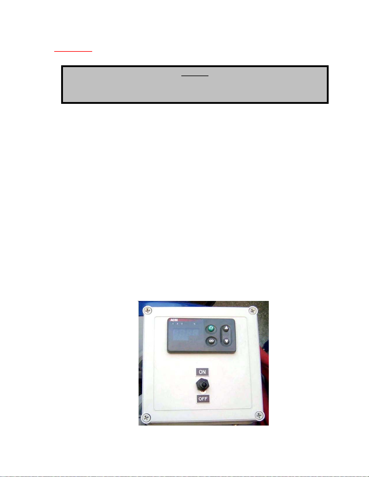
3.3.12 Set the switch on the control panel (Fig. 1) to the “on” position.
3.3.13 The temperature controller display will now show the incoming water temperature and the
burner will fire.
3.3.14 As the burner cycles, the water temperature will increase. The display on the digital
temperature controller will show the outgoing water temperature. When the heater reaches
the set temperature, the burner will begin to short cycle to maintain the set temperature.
3.3.15 The temperature controller is programmed from factory at 92°F / 33°C for optimal
temperature comfort.
3.3.16 If applicable, place the decontamination solution container in designated area close to Versi
Heat II unit and submerge the solution dosing pump pickup line fully into solution. Now set
the solution percentage to desired number by turning the handle adjacent to the pick up line
on dosing pump.
3.3.17 Turn solution valve/s on for solution delivery. A tapping sound can be heard when the
solution pump is activated.
3.3.18 To stop solution injection, simply turn the solution valve/s off.
3.4 Shut-Down Procedure:
3.4.1 Set the switch on the control panel (Fig. 1) to the “off” position.
3.4.2 Allow unit to cool down.
Proprietary Information: This document is the property of ADVANCED CONTAINMENT SYSTEMS, Inc. It shall not be copied
or duplicated and shall not be submitted to outside parties without the company consent.
Page 5 of 122/14/2005

DOCUMENT NUMBER: OPMM-007E-R0
3.4.3 Turn water supply off.
3.4.4 Disconnect power supply cable.
3.4.5 Disconnect water supply hose and delivery hoses from all discharge ports.
3.4.6 Water heater will now gravity-drain completely.
3.4.7 In very cold conditions, additional protection is accomplished by “blowing” the unit down
using a pressurized air source, to avoid any freezing.
4. PREVENTIVE MAINTENANCE:
4.1 Although Versi Heat II is a low maintenance water heating system, some periodic care is still
required for optimum operation. Outlined in the next few pages are those maintenance operations
that the operator/maintenance personnel should perform periodically. Maintenance cycle periods
naturally depend on amount of use.
4.2 Inlet Strainer (Fig. 2):
4.2.1 Versi Heat II is outfitted with an inlet “Y” strainer (Fig. 2) located at the inlet of the heater
coil. The screen in the strainer keeps contaminants from flowing into the water stream
feeding the shower booms. It also protects “wetted” mechanical components of the water
heater.
4.2.2 To clean it, loosen the screen cap on the “Y” strainer (Fig. 2):
Fig. 2 Inlet Strainer
“Y” Strainer
Proprietary Information: This document is the property of ADVANCED CONTAINMENT SYSTEMS, Inc. It shall not be copied
or duplicated and shall not be submitted to outside parties without the company consent.
Page 6 of 122/14/2005

DOCUMENT NUMBER: OPMM-007E-R0
4.2.3 Remove the cap and check the screen (Fig. 3) for contamination. Rinse the screen with
water if necessary.
Fig. 3 Strainer Gasket
4.2.4 When reassembling the strainer make sure, the screen is properly seated in both, the body
and the cap, and the gasket is properly located.
4.3 Temperature and Pressure Relief Valve (Fig. 4):
4.3.1 The temperature and pressure relief valve’s function is to protect the heater coil and by
extension, the rest of the warm water supply system from elevated temperature and
pressure. Periodically it is necessary to “exercise” it to make sure it is working correctly.
This also flushes accumulated contaminants if any from the internal valve seat area.
4.3.2 The Temperature and Pressure Relief Valve (Fig. 4) is located at the top of the water
heater and the manual activation handle is atop the valve.
Fig. 4 Temperature and Pressure Relief Valve
Proprietary Information: This document is the property of ADVANCED CONTAINMENT SYSTEMS, Inc. It shall not be copied
or duplicated and shall not be submitted to outside parties without the company consent.
Page 7 of 122/14/2005

DOCUMENT NUMBER: OPMM-007E-R0
4.3.3 To exercise the valve, set the switch on the control panel (Fig. 1) to the “off” position.
4.3.4 Close all the water heater delivery valves (Fig. 5).
Fig. 5 Water Heater Delivery Valves
Deliver
y
Valves
4.3.5 Now lift the manual activation handle on the T&P relief valve (Fig. 6) for about 5 to 10
seconds. Water will now flow out of the discharge line and flush the internal valve seat.
Fig. 6 Temperature & Pressure Relief Valve - Open
Proprietary Information: This document is the property of ADVANCED CONTAINMENT SYSTEMS, Inc. It shall not be copied
or duplicated and shall not be submitted to outside parties without the company consent.
Page 8 of 122/14/2005

DOCUMENT NUMBER: OPMM-007E-R0
4.3.6 Lower the manual activation handle on the T&P valve (Fig. 6), open the water heater
delivery valves (Fig. 5), and set the switch on the control panel (Fig. 1) to the “on” position.
4.4 Fuel filter (Fig. 7):
ATTENTION
VERSI HEAT II NEEDS TO BE OPERATED WITH FRESH AND CLEAN FUEL. STALE AND/OR
CONTAMINATED FUEL IS THE MOST COMMON SOURCE OF PROBLEMS WITH WATER HEATERS.
VERSI HEAT II NEEDS TO BE OPERATED REGULARLY TO KEEP THE FUEL SUPPLY, FRESH AND
CLEAN. IF IDLE FOR MORE THAN A MONTH, CONTACT YOUR DISTRIBUTOR FOR ASSISTANCE.
4.4.1 Fuel filter care is an essential part of Versi Heat II’s preventative maintenance procedure,
and it needs to be cleaned periodically to prevent major contamination.
4.4.2 To start the procedure, place a container under the filter to catch the fuel that will be spilled
during disassembly. Now with a 5/8” wrench (Fig. 7) loose the bolt on the top of the filter
head while firmly holding the filter bowl.
4.4.3 At times, a dry seal between the bowl and the filter head can make the bowl hard to
separate. A gentle tap on the upper part of the bowl while firmly supporting the filter will
help separate the parts.
Fig. 7 Fuel Filter
4.4.4 Remove the center bolt (Fig. 8) making sure, the red washer (see arrow in Fig. 8) is not
lost. This sealing washer prevents fuel leaks when the burner is off and air leaks into the
fuel system when the burner is on.
Proprietary Information: This document is the property of ADVANCED CONTAINMENT SYSTEMS, Inc. It shall not be copied
or duplicated and shall not be submitted to outside parties without the company consent.
Page 9 of 122/14/2005

DOCUMENT NUMBER: OPMM-007E-R0
Fig. 8 Fuel Filter – Center Bolt
4.4.5 Separate the bowl (Fig. 9) from the head to expose the fiber element and pour the fuel in
bowl into the container.
Fig. 9 Fuel Filter – Fiber Element
Proprietary Information: This document is the property of ADVANCED CONTAINMENT SYSTEMS, Inc. It shall not be copied
or duplicated and shall not be submitted to outside parties without the company consent.
Page 10 of 122/14/2005

DOCUMENT NUMBER: OPMM-007E-R0
4.4.6 The filter is composed of several bands of wool and a center screen. It is not necessary to
disassemble the components of the element to clean it, just rinse properly. Although the
element is reusable (if properly cleansed with mineral spirits and blown clear), we
recommend one or two elements be stocked at all the time for quick turn around. Please
contact your local distributor for replacement parts.
4.4.7 A breakdown of the fuel filter is shown in Fig. 10.
Fig. 10 Fuel Filter - Breakdown
4.5 To Reassemble:
4.5.1 To reassembly the filter, simply follow the reverse order. Make sure to insert the filter
element carefully to avoid damage the screen. Verify all seals are properly seated before
placing the heater back in service to assure there are no fuel or air leaks.
4.6 Note: In cases of heavy fuel filter contamination, the entire fuel system should be checked. Severe
contamination can affect the fuel pump and/or the fuel nozzle assembly. This level of service is for
a trained oil fired burner technicians, please contact your distributor for an approved service
provider in your area.
Proprietary Information: This document is the property of ADVANCED CONTAINMENT SYSTEMS, Inc. It shall not be copied
or duplicated and shall not be submitted to outside parties without the company consent.
Page 11 of 122/14/2005

DOCUMENT NUMBER: OPMM-007E-R0
Proprietary Information: This document is the property of ADVANCED CONTAINMENT SYSTEMS, Inc. It shall not be copied
or duplicated and shall not be submitted to outside parties without the company consent.
Page 12of 122/14/2005
5. REPLACEMENT PARTS LIST:
Versi Heat Replacement Part List:
Item: Part Number: Descriptions:
1 56220105 Fuel Tank GI Jerry Can 5 Gal
2 56220106 Fuel Tank Holder
3 61010103 Fuel Tubing 1/4"
4 61080003 Hose Clamp #4
5 61080012 Hose Clamp #12
6 61090402 Hose Barb for Fuel Tank
7 61090404 Hose Barb for Fuel Pump
8 71240805 Cord Grip
9 72270401 Switch-Toggle On/Off
10 72271100 Flow Switch
11 83180101 Toggle Switch Boot
12 87060410 Pressure Regulator Valve
13 97000177 Garden Hose Swivel
14 97000180 Cable 18/4
15 97000209 Quick Disconnect Socket
16 97000210 Quick Disconnect Plug
17 97000219 Burner
18 97000224 Strainer
19 97000278 Valve Y-Connector
20 97000284 Fuel Filter 1/4" FPT In/Out
21 97000384 GFCI Outlet
22 97000477 Temperature Controller
23 97000478 Thermo Coupler
24 97000479 High Limit Switch
25 97000480 Power Relay 30 Amp
26 97000510 Boiler Coil W/O Skin
27 97001075 Switch Push Button
28 Call Srvc Cntr Flue Cap
29 Call Srvc Cntr Heater Coil
30 Call Srvc Cntr Burner Gasket
31 Call Srvc Cntr Burner Fuel Nozzle
32 Call Srvc Cntr Burner Electrodes
33 Call Srvc Cntr Burner Blower Motor
34 Call Srvc Cntr Burner Ignitor
35 Call Srvc Cntr Burner Blower Wheel
This manual suits for next models
1
Table of contents
Popular Water Heater manuals by other brands

MediaShop
MediaShop AQUADON SMART HEATER Instructions for use

Triton
Triton T30i Installation and operating instructions

RBI
RBI Infinite Energy2 IW199 Installation and operation instructions

AquaStar
AquaStar 125 VP Installation and operating instructions

Kardia
Kardia Standard V.102 user manual

Rotenso
Rotenso Thermos Series Installation and user manual