Actavo BoSS SOLO 700 User manual
www.actavo.com
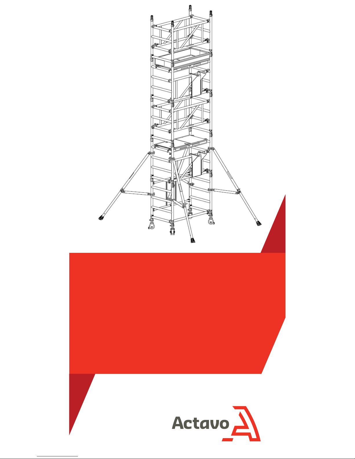
BoSS
SOLO700
One Man Aluminium Tower
3T - Through the Trapdoor Method
www.actavo.com
BoSS SOLO700 USER GUIDE
Safety First
Mobile Towers - 3T Method
INTRODUCTION
Please read this Userguide carefully. Please note that diagrams
are for illustrative purposes only. User guides are also available
to download - please contact us for details.
BoSS aluminium towers are light-weight scaffold towers used
throughout the building and construction industry for both
indoor and outdoor access solutions where a stable and secure
platform is required. Ideal for maintenance and installation work
or short term access, the highly versatile towers provide a strong
working platform at a variety of heights.
The law requires that personnel erecting towers must be
competent. Any person erecting, dismantling or altering a BoSS
Zone 1 mobile tower must have a copy of this guide.
For further information on the use of mobile access and working
towers consult the PASMA code of practice. If you need further
information, design advice, additional guides or any other help
with this product, please contact Actavo on 0800 214 005 or
email quoteme@actavo.com
COMPLIANCES
The BoSS Clima aluminiumsystemhas been tested and certified
to EN 1004: 2004 Class 3
Instruction Manual EN 1298-IM-EN
PREPARATION AND INSPECTION
Inspect the equipment before use to ensure that it is not
damaged and that it functions properly. Damaged or incorrect
components should not be used.
Safety First
SAFE USE
•Check that all components are on site, undamaged and that
they are functioning correctly - (refer to Checklist and
Quantity Schedules). Damaged or incorrect components
should not be used.
•Check if the ground on which the mobile access tower is to be
erected and moved is capable of supporting the tower.
•The safe working load is 275 kgs (606lbs) per platformlevel,
uniformly distributed up to amaximumof 950kgs (2100lbs),
per tower (including self weight).
•Towers must always be climbed fromthe inside using the
built-in ladder during assembly and use.
•It is recommended that towers should be tied to asolid
structure when le unattended.
•Adjustable legs should only be used for levelling.
LIFTING OF EQUIPMENT
•Tower components should be lied using areliable liing
material (e.g. strong rope), employing areliable knot (e.g.
clove hitch), to ensure safe fastening and always li within the
footprint of the tower.
•Assembled mobile towers
FREEPHONE: 0800 214 005
www.actavo.com
BoSS SOLO700 USER GUIDE
Safety First
STABILISERS/BALLAST
•Stabilisers or outriggers and ballast weights should always be
fitted when specified.
•The Quantity Schedules showthe recommended stabilisation.
In circumstances where there is restricted ground clearance for
stabilisers/outriggers, contact your supplier for advice. Ballast
must be made up of solid materials (i.e. not water or loose
sand) and should not be positioned to overload individual legs.
Ballast should be secured against accidental removal where
practicable, and be supported on the lowest rung of the
bottomframe.
MOVEMENT
•The tower should only be moved by manual eort, and only
fromthe base.
•Beware of live electrical apparatus when moving the tower
(particularly overhead), plus wires or moving parts of
machinery.
•No person or materials should be on the tower during
movement.
•Caution should be exercised when wheeling atower over rough,
uneven or sloping ground, taking care to unlock and lock
castors. If stabilisers are fitted, they should only be lied a
maximumof 25mm above the ground to clear ground
obstructions.
•The overall height of the tower when being moved should not
exceed 2.5 times the minimumbase dimensions, or 4 metres
overall height.
•Before use, check that the tower is still correct and complete.
•Aer every movement of the tower, use aspirit level to check
that it is vertical and level and set the adjustable legs as
required.
•Do not move the tower in wind speeds over 7.7 metres per
second (17mph).
Safety First
DURING USE
•Beware of high winds in exposed, gusty or mediumbreeze
conditions. We recommend that in wind speeds over 7.7
metres per second (17 mph), cease working on the tower and
do not attempt to move it. If the wind becomes astrong breeze
(expected to reach 11.3 metres per second - 25 mph) tie the
tower to arigid structure. If the wind is likely to reach gale
force (over 18 metres per second - 40 mph), the tower should
be dismantled.
•Beware of open ended buildings, which can cause afunnelling
effect.
•Do not abuse equipment. Damaged or incorrect components
should not be used.
•Raising and lowering components, tools, and/or materials by
rope should be conducted within the lower base. Ensure that
the safe working load of the supporting decks and the tower
structure is not exceeded.
•The assembled tower is aworking platformand should not be
used as ameans of access or egress to other structures.
•Beware of horizontal forces (e.g. power tools) which could
generate instability. Maximumhorizontal force 20kg.
•Mobile towers are not designed to be suspended - please refer
to your supplier for advice.
•Do not use boxes or stepladders or other objects on the
platformto gain extraheight.
FREEPHONE: 0800 214 005
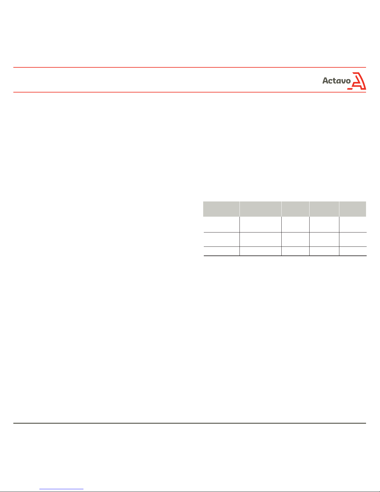
WIND BEAUFORT BEAUFORT SPEED IN SPEED IN
DESCRIPTION SCALE NO. MPH M/SEC
Medium
Breeze
Strong Breeze
Gale Force
Raises dust and
loose paper, twigs
snap o
Large branches in
motion, telegraph
wires whistle
Walking is dicult
4
6
8
8-12
25-31
39-46
4-6
11-14
17-21
www.actavo.com
BoSS SOLO700 USER GUIDE
Safety First
TIES
•Ties should be used when the tower goes beyond its safe
height, beyond the limits of the stabilisers/outriggers or if
there is adanger of instability. They should be rigid, two way
ties fastened to both uprights of the frame with load-bearing
right angled or swivel couplers. Only couplers suitable for the
50.8mm diameter tube of the tower should be used. Ideally,
ties should be secured to both faces of asolid structure by
means of anchorages.
•The tie frequency may vary depending on the application, but
they should (at aminimum) be every 4 metres in height.
•For further information on tying-in atower please contact your
supplier or BoSS.
MAINTENANCE - STORAGE -
TRANSPORT
•All components and their parts should be regularly inspected
to identify damage; particularly to joints. Lost or broken parts
should be replaced, and any tubing with indentation greater
than 5mm should not be used and put to one side for
manufacture repair. Adjustable leg threads should be cleaned
and lightly lubricated to keep themfree running.
•Brace claws, frame interlock clips, trapdoor latches and
platformwindlocks should be regularly checked to ensure they
lock correctly.
•Components should be stored with due care to prevent
damage.
•Ensure components are not damaged by excessive strapping
forces when transported.
Safety First
FREEPHONE: 0800 214 005
Safety Checklist
Mobile Towers - 3T Method
CHECKLIST
Ensure all components are present (see quantity
schedule on page 9)
Inspect components prior to erection
Inspect tower prior to use
Tower upright and level
Castors locked and legs correctly adjusted
Diagonal braces fitted
Stabilisers/outriggers fitted as specified
Platforms located and windlocks on
Toeboards located
Check guardrails are fitted correctly. See
illustration below.
www.actavo.com
BoSS SOLO700 USER GUIDE
FREEPHONE: 0800 214 005
Ensure all brace claws, cam-locks and adjustable
legs operate correctly
Ensure castors rotate freely and brakes lock
Re-inspect the tower every seven days or less
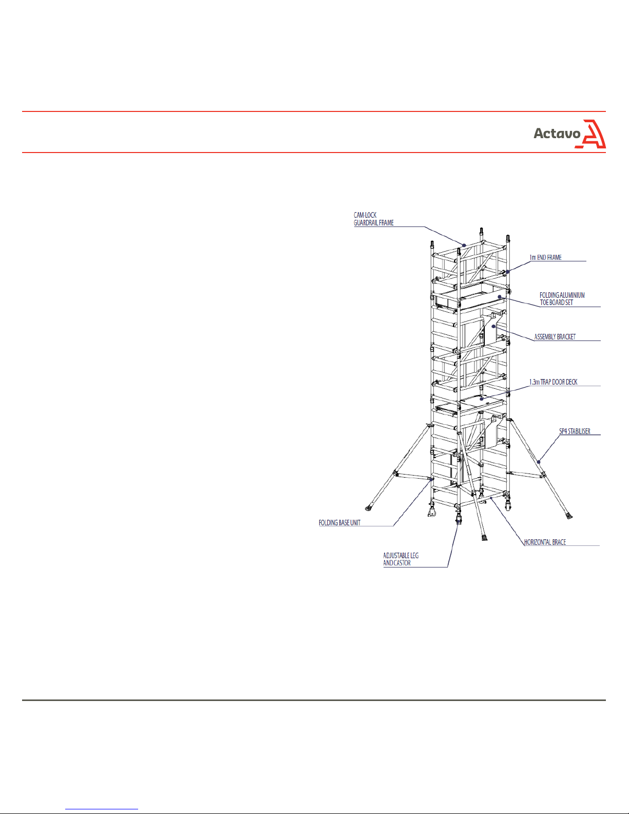
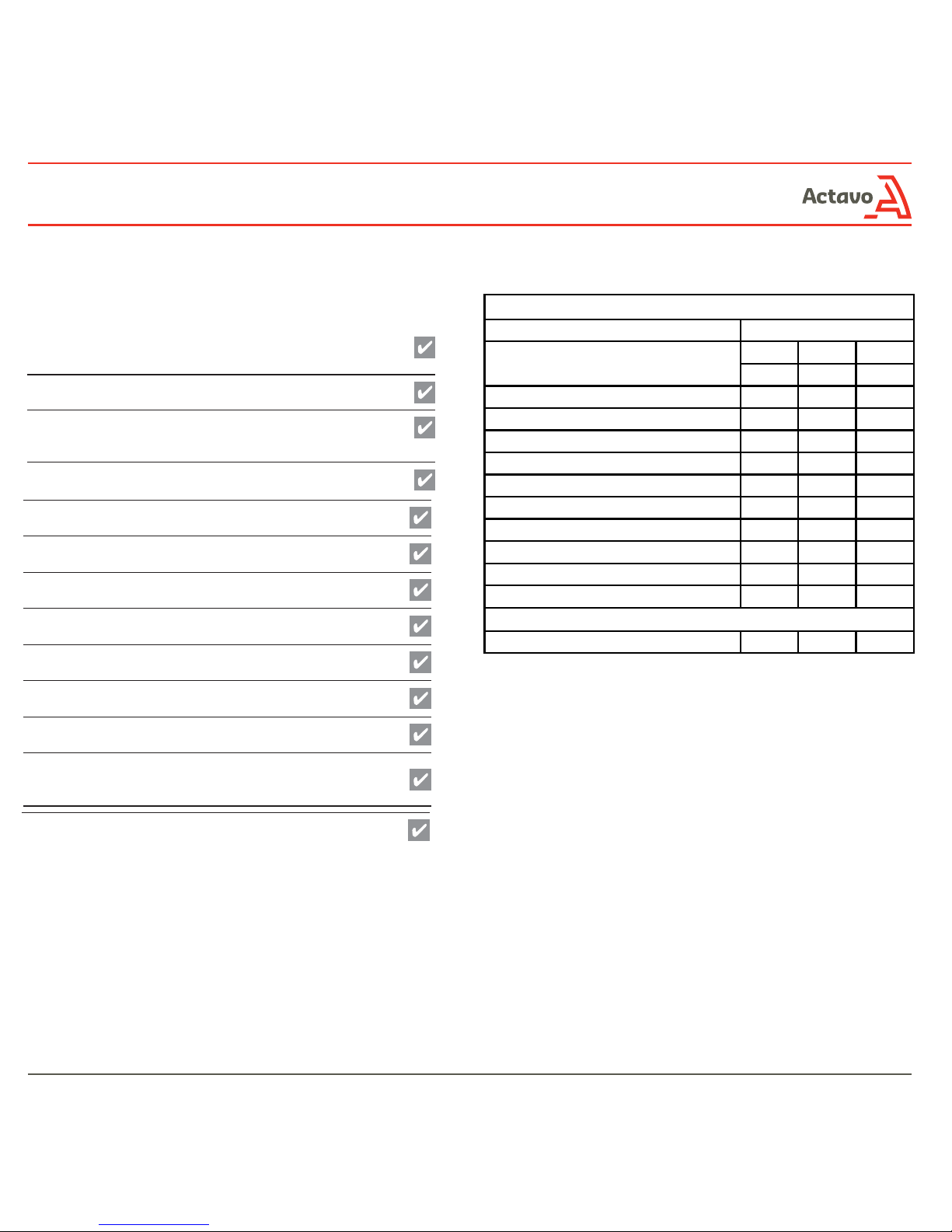
Quantity Schedule
BoSS Solo 700 - 1.3m x 0.7m
3T Method Internal or external use
Component
Working Height (m)
Platform Height (m)
4.2 5.2 6.2
2.2 3.2 4.2
Castor 444
Adjustable Leg 444
4 Rung End Frame (1.0m high x 0.7m wide) 468
Folding Base Unit 111
1.3m CamLock Guardrail Frame 356
1.3m Trap Door Deck 122
1.3m Horizontal Brace 111
Aluminium Folding Toe Board 111
Assembly Bracket 222
SP4 Telescopic Stabiliser 444
Total Self Weight of Tower (Kg) 93 121 134
Table of contents


