Actiforce Aluforce Pro 140 M User manual
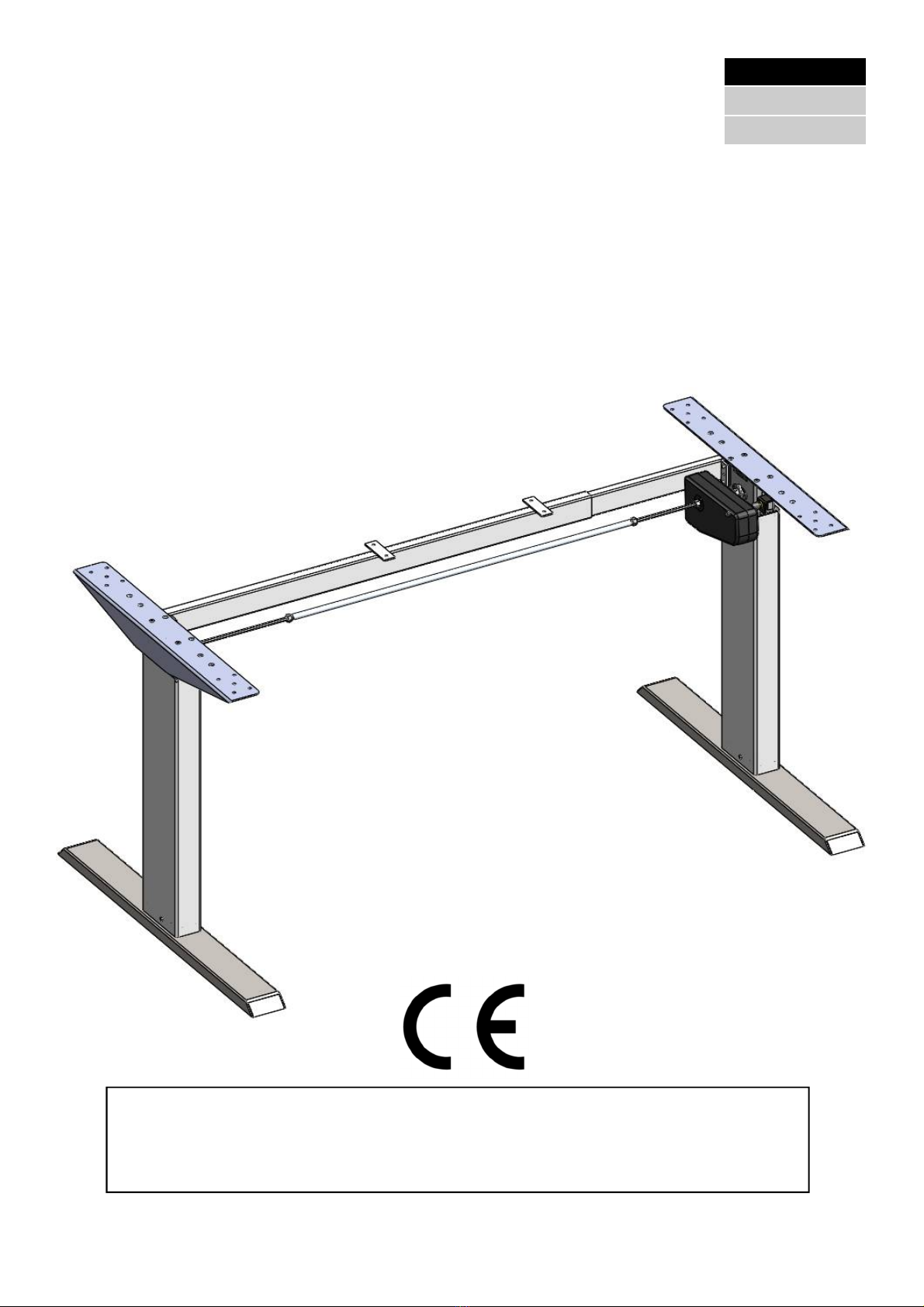
Frame for an electro-motorized workstation
Aluforce Pro 140 M
Read this manual thoroughly and store in a safe place!
Assembly Manual
P19300-1EN-DE-NL
English
Deutsch
Nederlands

2
Content
1 GENERAL ....................................................................................................................................................... 3
1.1 Local value of the assembly/operating manual ...................................................................................... 3
1.2 Intended use ........................................................................................................................................... 3
1.3 Improper use .......................................................................................................................................... 3
1.4 Content box ............................................................................................................................................ 4
2 SAFETY INFORMATION .............................................................................................................................. 5
2.1 Symbols/warnings .................................................................................................................................. 5
2.2 Symbols used on the workstation frame ................................................................................................. 5
2.3 Organizational measures ........................................................................................................................ 5
2.4 Informal safety measures ....................................................................................................................... 5
2.5 Note for those assembling the workstation ............................................................................................. 5
2.6 Transport and assembly ......................................................................................................................... 5
2.7 Safety/protective measures ..................................................................................................................... 5
2.8 Use of the workstation frame ................................................................................................................. 6
2.9 Specific dangers ...................................................................................................................................... 6
2.10 In an emergency ..................................................................................................................................... 6
2.11 Maintenance and upkeep ....................................................................................................................... 6
2.12 Cleaning ................................................................................................................................................. 6
2.13 Persistent risks ....................................................................................................................................... 6
3 ASSEMBLY ..................................................................................................................................................... 7
3.1 Checking the items supplied ................................................................................................................... 7
3.2 Packaging ............................................................................................................................................... 7
3.3 Tightening torques for screws used ........................................................................................................ 7
3.4 Assembly of the workstation .................................................................................................................. 7
3.4.1 Pre-assembly of the Crossbar ............................................................................................................... 7
3.4.2 Mounting the Crossbar ........................................................................................................................ 8
3.4.3 Mounting the Feet .............................................................................................................................. 10
3.4.4 Mounting the Hexagon Shaft ............................................................................................................. 12
3.4.5 Mounting the Top Supports ................................................................................................................ 14
3.4.6 Mounting the Drive Unit .................................................................................................................... 15
3.4.7 Adjustment of the frame width ............................................................................................................ 16
3.4.8 Connecting the Cables Drive Unit ....................................................................................................... 17
3.4.9 Frame test without tablet op ................................................................................................................ 18
3.4.10 Note: Mounting the table top .............................................................................................................. 18
3.4.11 Note: Mounting the power supply underneath the table top......................................................................18
3.4.12 Identification sticker...................................................................................................................................18
4 TECHNICAL SPECIFICATIONS ................................................................................................................. 19
5 OPERATION AND INDICATORS ................................................................................................................ 21
5.1 Indicators .............................................................................................................................................. 21
6 CUSTOMER SERVICE ................................................................................................................................ 22
7 MANUFACTURER ........................................................................................................................................ 22
8 RECYCLING .................................................................................................................................................. 22
8.1 Taking the workstation out of active duty ............................................................................................. 22
8.2 Taking the workstation apart ................................................................................................................ 22
8.3 Recycling ............................................................................................................................................... 22

3
1 General
1.1 Local value of the assembly/operating manual
The guiding principle for safe use and trouble-free operation of this workstation frame is knowledge
of basic safety information and regulations. This assembly/operating manual contains the most im-
portant information needed for assembling and operating the workstation frame safely. This assem-
bly/operating manual, in particular the safety information contained herein, must be observed by any
person building the frame and working on the finished surface. More importantly, the rules and regu-
lations applying to accident prevention in the locality in which the workstation frame is to be used
must be observed at all times.
1.2 Intended use
The workstation frame must be used only as an electrically height-adjustable workstation for sitting/
standing use in offices or other enclosed areas. The frame must be used for this purpose only. The
workstation frame may be set up and operated solely in office environments. Do not use the work-
station frame in the home. Please observe the provisions of Section 2, Safety Information. Children
may be unaware of the dangers presented by the workstation frame if unsupervised. Any other use
than the above shall be deemed improper. The manufacturer can in no way be held liable for damage
arising from improper use.
Intended use shall also include:
Observation of all information from the assembly/operating manual and
Prohibition of any sort of addition to/conversion of the workstation.
1.3 Improper use
Never use the workstation frame to lift people or loads.
Do not exceed the maximum load of the workstation frame (see Section 4, Technical Data).
Do not use the workstation frame in the home; alternatively, use it only in offices.
WARNING Any changes or modifications not expressly approved by the manufacturer
could void the user’s authority to operate the equipment.
4
12
04
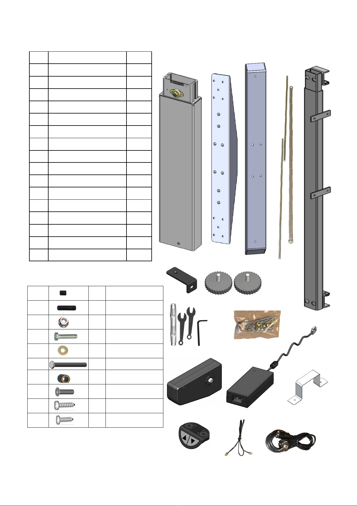
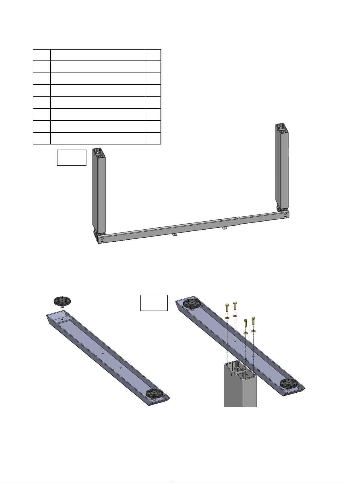
1.4 Content box
05
03
01
06
02
10
09
11
07
13
15
# Part name Qty
01 Leg 2
02 Top support 2
03 Foot 2
04 Hexagon shaft 2
05 Axle Drive 1
06 Crossbar 1
07 L-Bracket 1
08 Foot adjusters 4
09 Tools 1
10 Mounting hardware kit 1
11 Drive unit 1
12 Power supply 1
13 Holder 1
14 Up/down switch 1
15 Cable up/down switch 1
16 Power Cord 1
08
14 16
10.1 2x Set Screw M6x6
10.2 4x Set Screw M6x20
10.3 6x Flange Nut M6
10.4 8x Hex Bolt M6x25
10.5 9x Washer M6
10.6 1x Hex Bolt M6x80
10.7 1x Spacer
10.8 9x CSK M5x25
10.9 2x Chipboard 4.5x20
10.10 26x Chipboard 4.5x16

5
2 Safety Information
2.1 Symbols/warnings
The assembly/operating manual uses the following terms and signs to indicate dangers:
2.2 Symbols used on the workstation frame
2.3 Organizational measures
The workstation frame can best be assembled by two people. Turning the frame, once the
work surface has been fitted, is a task in particular which requires two people!
2.4 Informal safety measures
Keep the assembly/operating manual in the place where the workstation frame is used at all
times.
Make sure that all safety information on the table (see Section 2.2, Symbols used on the
workstation frame, page 5) is legible, replacing the same if necessary.
2.5 Note for those assembling the workstation
The workstation must be assembled/worked on by persons over the age of 16.
The persons referred to above must have read and understood the assembly/operating manu-
al.
2.6 Transport and assembly
The workstation frame must be moved by two persons only, and in such cases must be re-
tracted.
Do not drag or pull the workstation frame over the floor.
Assemble the workstation frame with the supplied tools only. They are the only tools which
ensure that the screws can be tightened to the correct torque.
2.7 Safety/protective measures
Replace the drives if the circuit breaker in the drives fails. Faulty circuit breakers will not
switch off the drive in the top/bottom setting. In such cases, the workstation frame has been
taken to the mechanical stop and can no longer be raised/lowered.
This symbol indicates an immediate threatening situation for any person’s life
or health. Failure to adhere to such information may have serious consequences
for health, or could even result in life-threatening injury or death.
This symbol indicates important information. Failure to adhere to such infor-
mation could lead to damage to the workstation.
Do not place objects or parts of the body under the workstation frame or be-
tween the cross members. This could cause serious injury.
Do not exceed the maximum permitted load on the workstation frame. Over-
loading could lead to breakage and serious injury as a consequence.

6
2.8 Use of the workstation frame
Do not allow children to use the workstation frame unsupervised. Children may be unaware
of the dangers presented by the workstation frame. They would be in serious danger of injur-
ing themselves, possibly even with fatal consequences. Further adjustment must then be im-
possible as a safeguard against use by children.
The workstation frame must only be used in appropriate areas (see Section 4 Technical Da-
ta).
Do not use the workstation frame on an uneven surface. In such conditions it will not be
steady.
Never exceed the maximum load on the workstation frame (see Section 4 Technical Data).
2.9 Specific dangers
When adjusting the height of the frame there is danger of injury. Make sure that there is no-
one else in the immediate surroundings of the frame.
When assembling the workstation frame, make sure there is ample space to avoid collisions
(i.e. inclination of roof, fixed objects, filing cabinets, waste-paper bins etc.) in all imaginable
directions.
Make sure there is ample space to avoid collisions if there are objects on the work surface
such as computers or computer peripherals.
Make sure there is clearance of at least 25 mm from all other furniture, all around the work-
station frame.
2.10 In an emergency
Stop using the workstation frame at once if you notice anything unusual (strange sounds
etc.).
Have the workstation frame repaired by specialists. Refrain from using the workstation
frame until it has been successfully repaired.
2.11 Maintenance and upkeep
The workstation frame and its components are low-maintenance items and need no special
regular maintenance.
Do not perform any repairs on the work surface or other components yourself.
Do not alter the construction of the work surface or its frame.
Any faulty components removed must be replaced with new, original components from the
manufacturer. Use only original replacement parts made by the manufacturer. Have any such
work carried out by a specialist, making reference to this Assembly/operating manual.
2.12 Cleaning
Dust the workstation frame once a week with a dry cloth.
Clean the workstation frame with a damp cloth and a weak solution of cleaner once a fort-
night.
2.13 Persistent risks
This workstation frame has been built to the state of the art and to recognized safety regulations.
Nonetheless, its use may constitute a risk to the health and safety of users or third parties, damage
to the workstation frame or to other items. The workstation frame must be used only:
for the purpose for which it was intended.
if it is completely safe to do so.

7
3 Assembly
3.1 Checking the items supplied
Carefully open the cardboard packaging.
In doing so, do not use any long knife blades. They may damage the components inside.
Check the parts supplied against the list in Section 1.4 Items supplied.
Check the contents for visible transit damage, paying particular attention to the electrical wiring.
In the event of any damage or incorrect components, contact customer services (see Section 7).
Do not attempt to assemble the workstation frame if there is any damage or if there are any in-
correct components.
3.2 Packaging
Remove the packaging. Treat as household waste/paper.
Observe national legislation.
3.3 Tightening torques for screws used
Assemble the workstation frame with the tools supplied only.
3.4 Assembly of the workstation
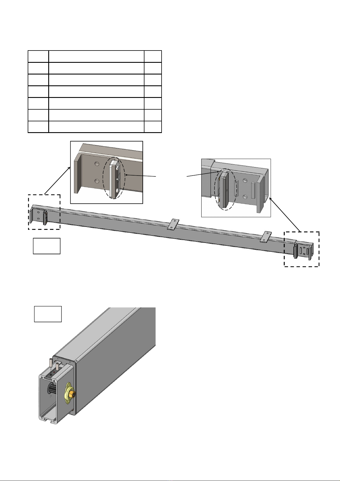
3.4.1 Pre-assembly of the Crossbar
Assemble the following components:
Before attempting assembly, read the safety information in Section 2.
Assemble the 2 set screws in the tapped holes.
Do not yet tighten the socket screws!
Tighten the socket screws only after assembling the components in step 3.4.7 Adjustment
of the frame width, page 16.
Indicative:
Frame set-up Wide/size tabletop
1,1 m 120 cm
1,3 m 140 cm
1,5 m 160 cm
1,7 m 180 cm
# Part name Qty
06 Crossbar 1
09 Allen key M3 1
10.1 Set Screw M6x6 2
Set screw M6x6
8
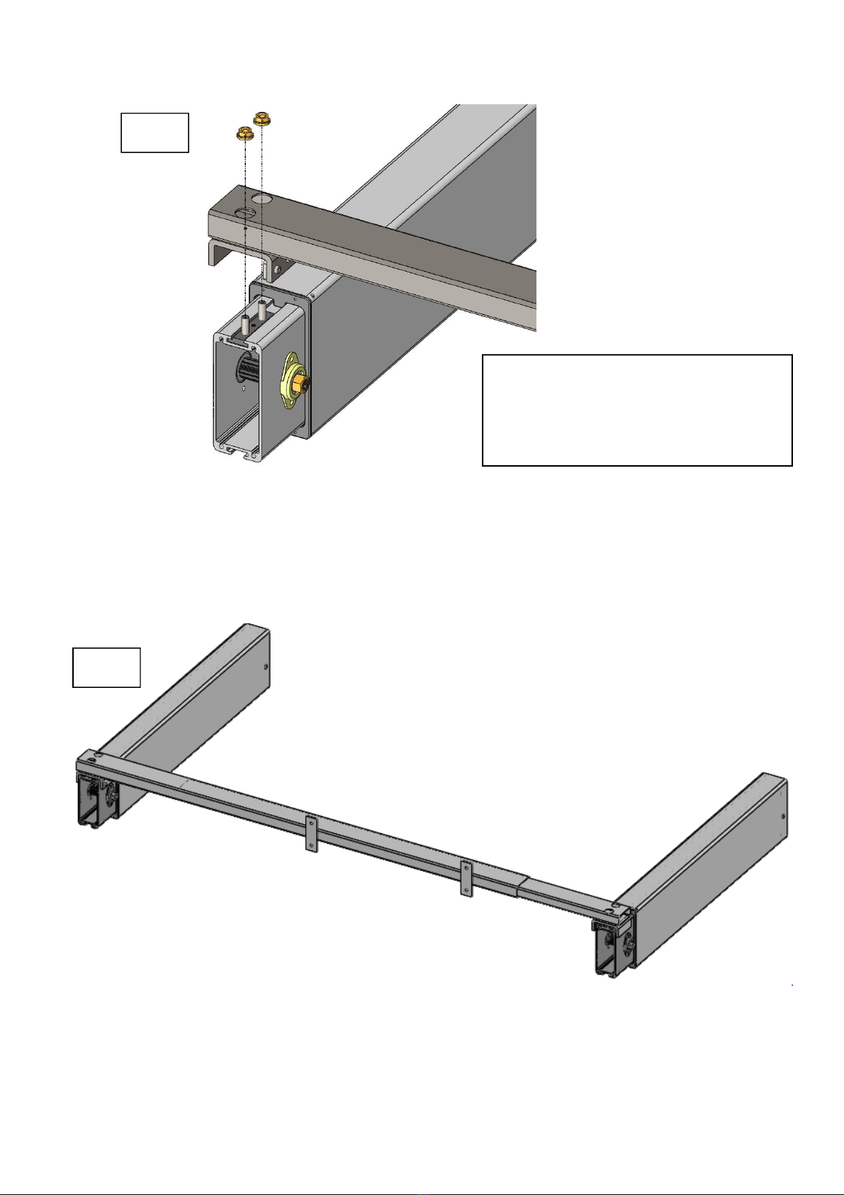
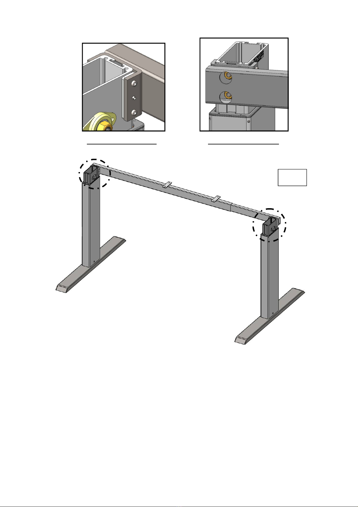
3.4.2 Mounting the Crossbar
Assemble the following components:
# Part name Qty
01 Leg 2
06 Pre-assembled Crossbar 1
09 Pipe Key M10 1
09 Allen key M3 1
10.2 Set Screw M6x20 4
10.3 Flange Nut M6 4
2
Photo 2
Place both legs flat on the floor, parallel to each other.
Be aware that both slide nuts point upwards.
Twist in 2 set screws into the slide nut of each leg.
Gently tighten the set screws with the Allen key M3.
Photo 1
Remove the transparent cellulose tape on the crossbar bracket before mount to the
leg unit.
1
Cellulose
Tape
9
3
4
Photo 3
Place the pre-assembled crossbar over the set screws.
Place the 4 flange nuts on the set screws.
Hand tighten the 4 flange nuts with the Pipe Key M10.
Important !!!
Do not fully tighten the flange nut.
Prevent the plate in crossbar bracket
from falling off!
10
3.4.3 Mounting the Feet
Assemble the following components:
# Part name Qty
03 Foot 2
08 Foot adjusters 4
09 Spanner M10 / Pipe Key M10 1
10.4 Hex Bolt M6x25 8
10.5 Washer M6 8
09 Allen Key M3 1
09 Pipe Key M10 1
5
Photo 6
Place 2 foot adjusters on the bottom of each foot.
Position the foot, like photo 6, in relation to the crossbar.
Connect each foot to a leg with 4 bolts and 4 washers.
Tighten the 8 bolts with the Spanner M10/ Pipe Key M10.
6
Photo 5
Turn the pre-assembled legs and crossbars up-side-down (with 2 persons).
The crossbars are now closest to the floor.
Secure the pre-assembled legs against falling over.
11
Photo 7
Turn the frame back on its foot (with 2 persons).
Now only :-
- FIRMLY tighten the 4 set screws on the crossbar bracket with Allen Key M3.
- FIRMLY tighten the 4 flange nuts on the crossbar with Pipe key M10.
7
Tighten the set screws. Tighten the flange nuts
12
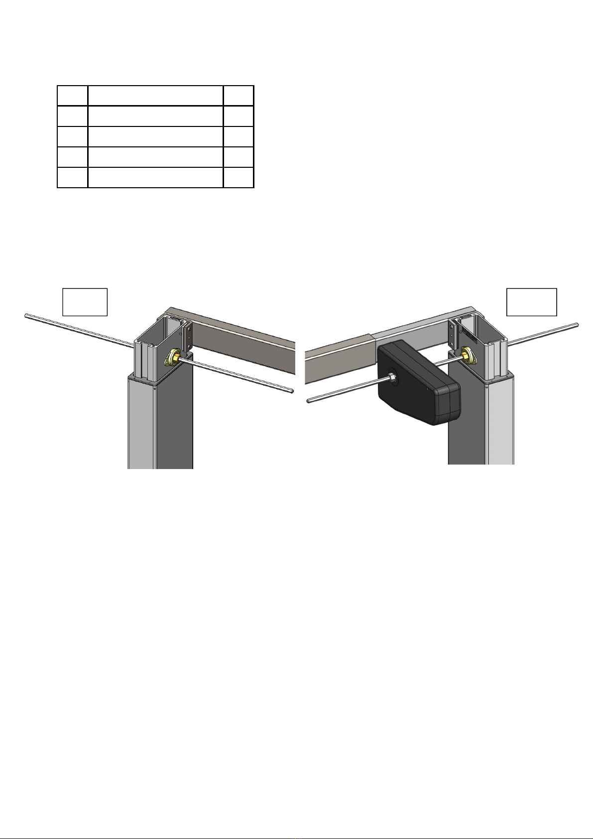
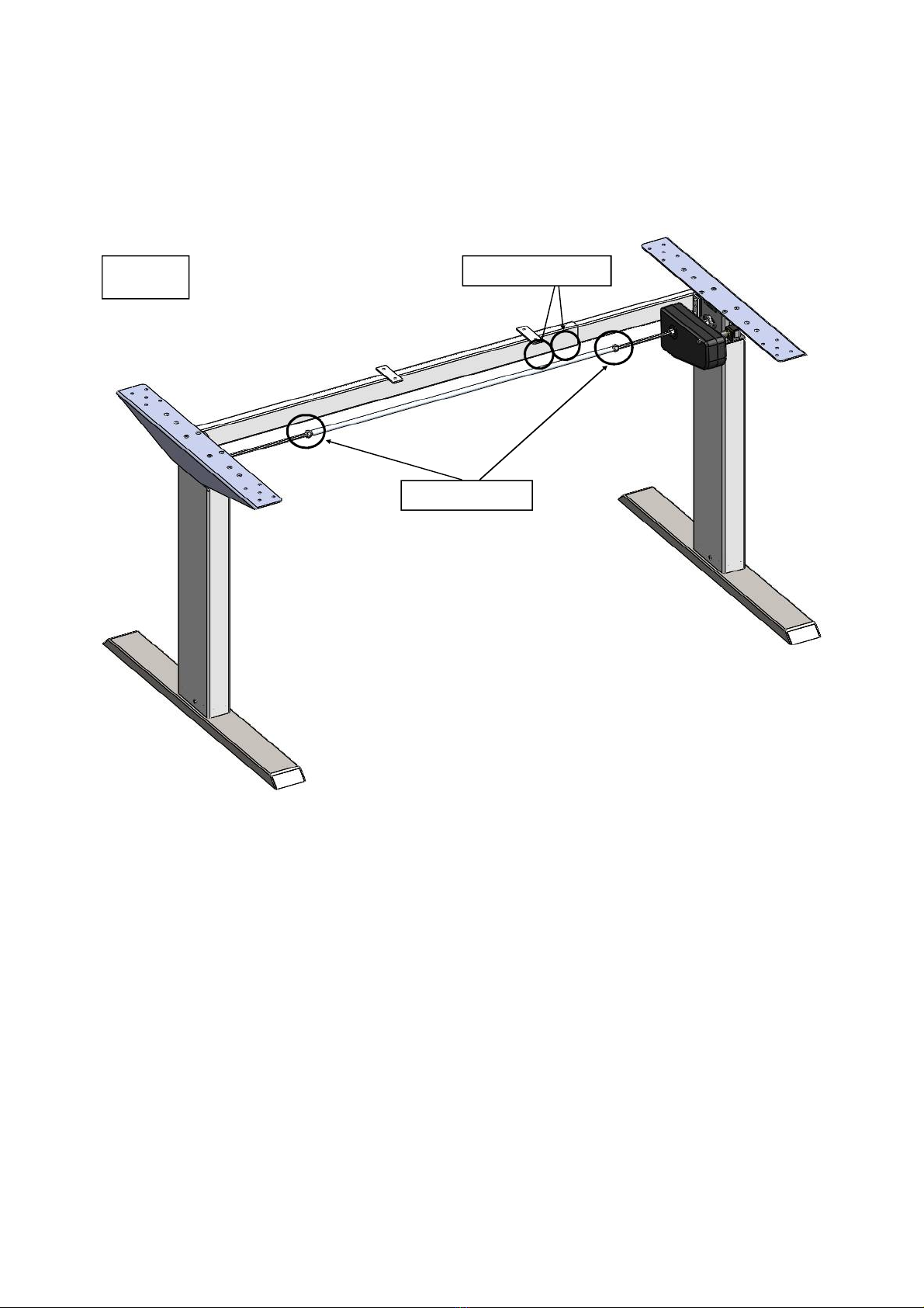
3.4.4 Mounting the Hexagon Shaft
Assemble the following components:
9 8
Photo 8
Slide the 1st hexagon shaft through the hexagon holes in the left legs until it stick ±15 cm
inside the frame.
Photo 9
Slide the 2nd hexagon shaft through the hexagon holes in the right legs until it stick ±15 cm
inside the frame.
Slide the drive unit over the hexagon shaft, at the side where the up-down switch needs to be
placed.
Be aware that both legs are completely in the lowest position.
Be aware that the drive units have not been connected to a power source before the complete
assembly has been done .
Be aware that all components are originally packed.
# Part name Qty
04 Hexagon shaft 2
05 Axle Drive 1
09 Spanner M10 1
11 Drive unit 1

13
Photo 10
Slide the axle drive over both hexagon shafts.
10
Photo 11
Slide both hexagon shafts inward, until they are flush with the outside surface of the leg.
11
14
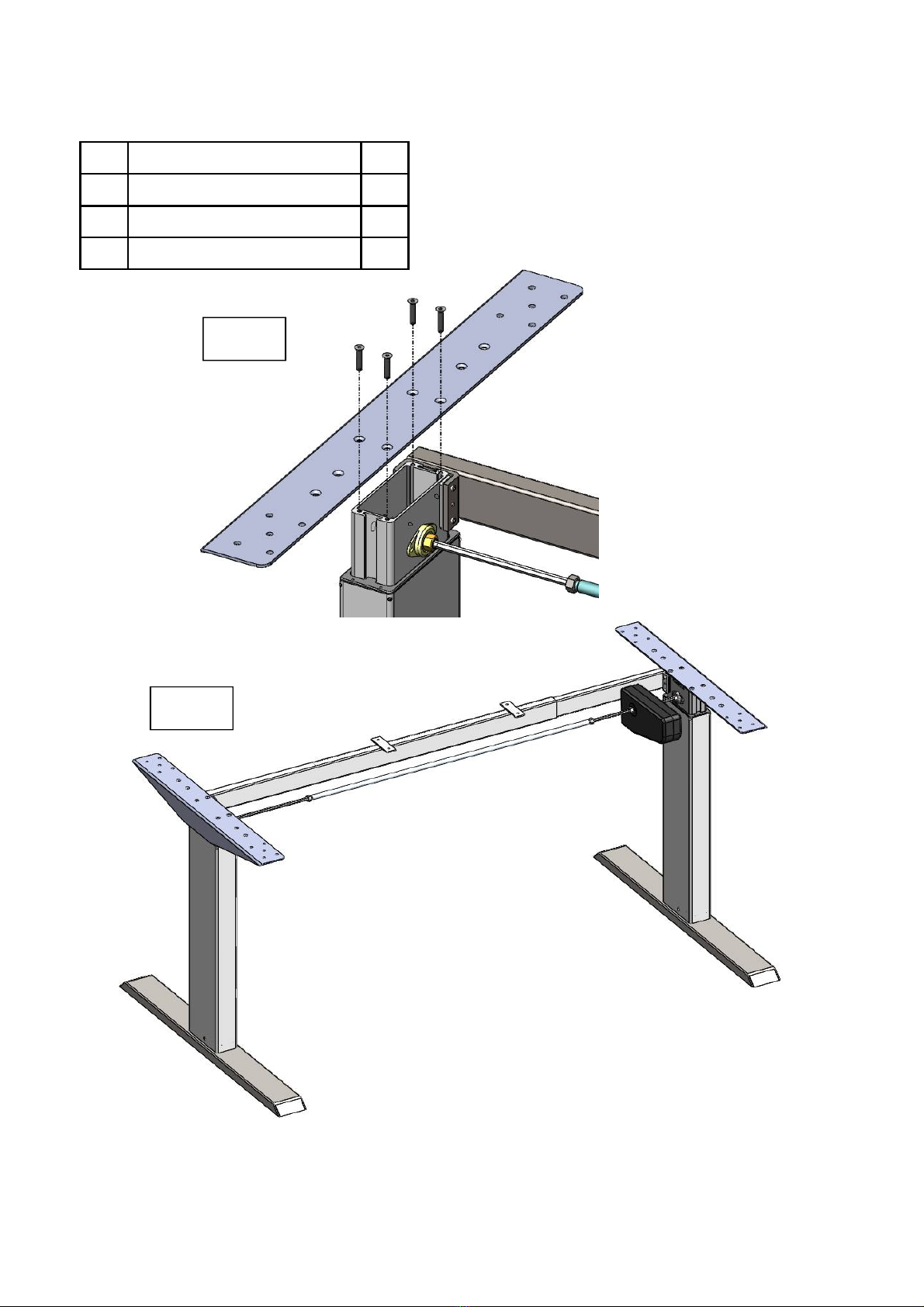
3.4.5 Mounting the Top Support
Assemble the following components:
# Part name Qty
02 Top support 2
09 Allen Key M3 1
10.8 CSK M5x25 8
Photo 12 & 13
Position the top support, like photo 12, in relation to the crossbars
Connect each top support to a leg with 4 CSK screws
Tighten the 8 screws with the Allen Key M3.
12
13

15
14 15
17
16
Parallel !!!
3.4.6 Mounting the Drive Unit
Assemble the following components:
Photo 14
Slide the long bolt (M6x80mm) with a washer through the specific hole in the drive unit.
Slide the plastic spacer and flange nut over the already placed bolt.
Photo 15
Slide the L-bracket over the already placed bolt (between the drive unit and the top support).
Screw another flange nut, as showed on the photo, over the bolt.
Photo 16
Adjust the drive unit towards the top support until L-Bracket’s hole align with hole on top support.
Screw the L-Bracket with CSK screw M5x25mm.
Photo 17
Be aware of that the drive unit is parallel in relation to the top support.
# Part name Qty
09 Spanner M10 1
10.6 Bolt M6x80 1
10.5 Washer M6 1
10.3 Flange nut M6 2
10.7 Plastic spacer 1
07 L-Bracket 1
10.8 CSK M5x25 1
09 Allen Key M3 1
16
3.4.7 Adjustment of the frame width
Pull the frame outward to the required wide (see chapter 3.4.1 Pre-assembly of the Crossbar)
Tighten the set screws in the bottom crossbar and pinching nuts on the axle drive with the
Spanner M10 only now.
18 Tighten set screw
Tighten the nut
17
Jumper
Keypad Cable
Powersupply
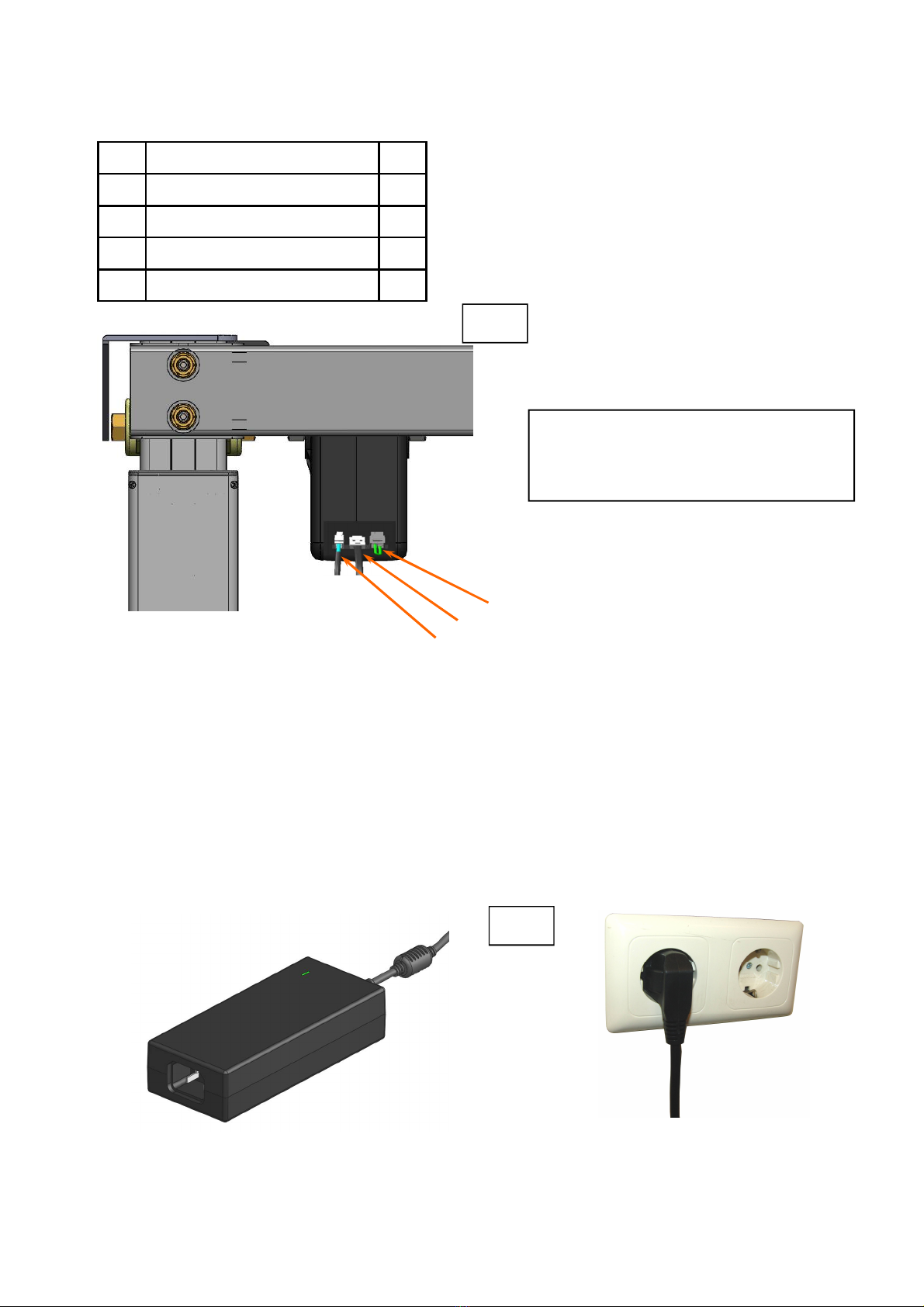
3.4.8 Connecting the Cables Drive Unit
Assemble the following components:
# Part name Qty
12 Power supply 1
14 Up/down switch 1
15 Cable up/down switch 1
16 Power Cord 1
19
Photo 19
Connect the cable up/down switch to the up/down switch and the correct connector of the
drive unit.
Connect the Power supply to the correct connector of the drive unit.
Make sure that the course of the cables is always unobstructed! Tighten the cables to the top
crossbar or top support with tape or cable binders (not included).
Photo 20
Connect the power cord to the power supply and stick the plug in to the electricity socket (100
-240 V~, 50-60Hz).
20
Keep the Jumper in the Drive Unit.
Without this plug the Drive Unit
will not work.

18
3.4.9 Frame test without tabletop
Photo 21
Press “UP” button, the frame goes up.
Release the button, the frame stops.
Press “DOWN” button, the frame goes down.
Release the button, the frame stops.
UP DOWN
21
Make sure that the workstation frame can move correctly and freely
at all times.
When there is a need to plug or unplug the wires from the motor or
the display/handset, always disconnect the controller from the main
power source.
3.4.10 Note: Mounting the table top
Refer to the separate manual of the table top.
3.4.11 Note: Mounting the power supply underneath the table top
Refer to the separate manual of the table top.
3.4.12 Identification sticker

19
4 Technical Specifications
Frame for Electro Motorised Workstation
Assembly Manual version P19300-1EN-DE-NL
Year of construction 2016
Production country Malaysia
System 1-step, external drive
Material Aluminium, steel and plastic
Stroke (max.) 46 cm
Frame load (max.) 60 kg
Frame weight ± 22 kg
Speed 0 kg frame load ± 21 mm/s
Speed 60 kg frame load ± 17 mm/s
Input power 100 - 240 V~, 2A, 50/60 Hz
Duty cycle 10 % (1 Minute on / 9 Minutes off)
Life span 10.000 Cycles (average use)
Noise level < 50 dB(A)
Environmental temperature Use 15 - 30°C
Environmental temperature Storing 10 - 50°C
Humidity Use <85%
Humidity Storing <50%
Maximum Storing time -
Indoor use only!!!

20
Minimum frame height 70 cm
Maximum frame height 116 cm
Maximum stroke 46 cm
Frame Width 110 - 170 cm
Frame Depth 75 cm
Minimum Tabletop Depth 60 cm
Maximum load 60 kg
4 Technical Specifications
110 - 170 cm 60 cm
75 cm
116 cm
Stroke 46 cm 70 cm
(* General Tolerance = ± 1 cm)
Other manuals for Aluforce Pro 140 M
2
Table of contents
Popular Desktop manuals by other brands


Compaq
Compaq BL10e - HP ProLiant - 512 MB RAM Technology overview

Shuttle
Shuttle DH410S Series user manual

Addonics Technologies
Addonics Technologies Storage Tower III user guide

Mitsubishi Electric
Mitsubishi Electric APRICOT 340 Owner's handbook

Epson
Epson EL 486UC+ Product information guide

Asus
Asus M32AAS user manual


