Action ACN-3560C User manual
ACN-3560C
2.4GHz Wireless Mono Camera
InstructionManual

2
CAUTION: TO REDUCE THE RISK OF ELECTRIC
SHOCK, DO NOT REMOVE COVER (OR BACK). NO
USER SERVICEABLE PARTS INSIDE. REFER SER-
VICING TO QUALIFIED SERVICE PERSONNEL.
This symbol is intended to tell the user that
parts inside the product present a risk or
electric shock to persons.
This symbol is intended to tell the
userthatimportantoperatingandser-
vicing instructions are included in the
Operating Instruction.
WARNING:
TO REDUCE THE RISK OF FIRE OR ELECTRIC
SHOCK, DO NOT EXPOSE THIS APPLIANCE TO
RAIN OR MOISTURE.

3
NOTE: The manufacturer is not responsible for any radio or
TV interference caused by unauthorized modifications to this
equipment. Such modifications could void the User’s au-
thority to operate the equipment.
TABLE CONTENTS
A. Introduction
B. Precautions
C£®£®
£®£®
£®Contents
D£®£®
£®£®
£®Controls/Jacks/Indicators
E£®£®
£®£®
£®Installation
F£®£®
£®£®
£®External Signal Sources Input
G£®£®
£®£®
£®Camera Setup
H£®£®
£®£®
£®Block Diagram
I. Operational Description
J£®£®
£®£®
£®Specifications

4
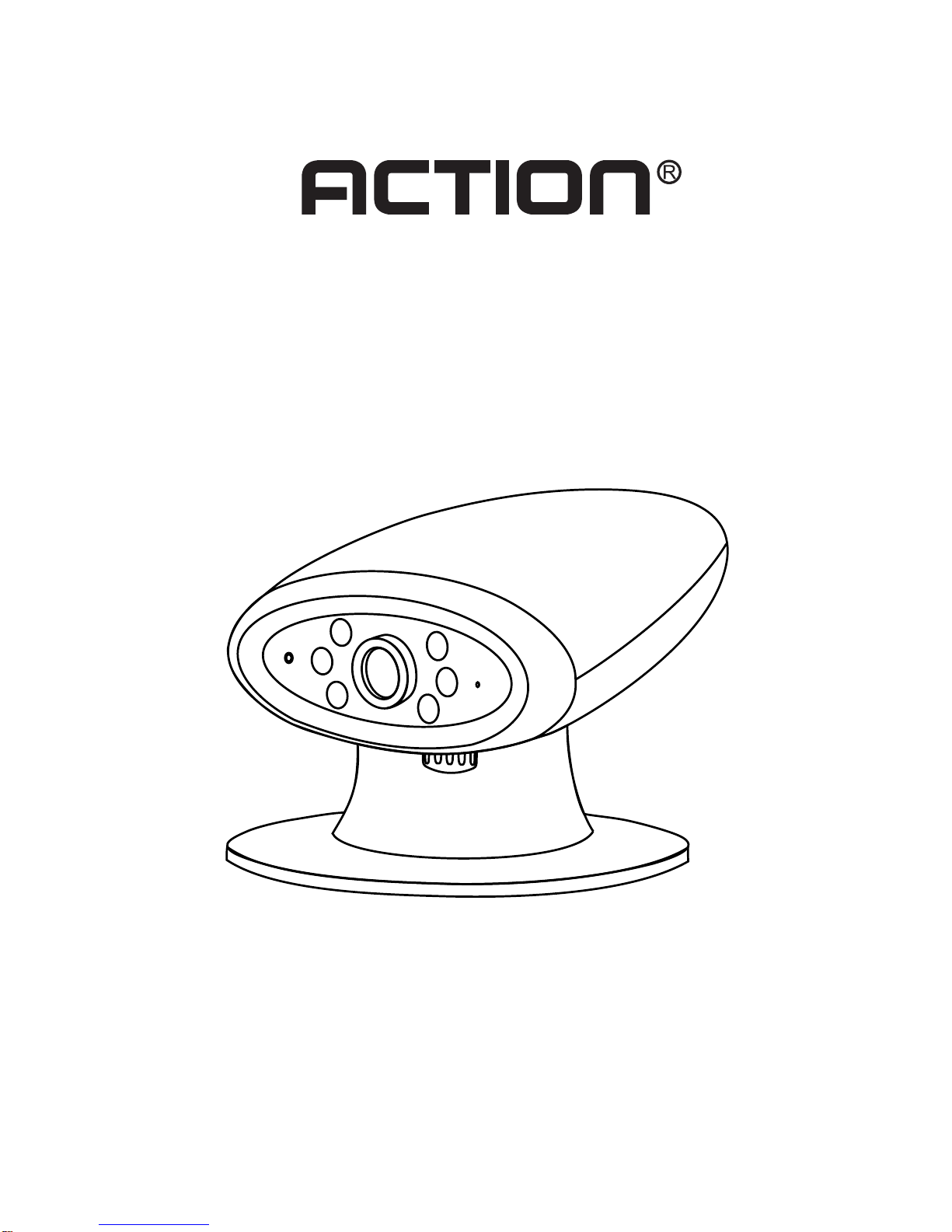
A. Introduction
Thanks for choosing this 2.4GHz wireless camera. This
system is designed for transmitting 2.4GHz audio/video
signals from the camera or connected signal source, to
the B/W monitor wirelessly. The camera can be placed
anywhere in the home, Baby room, or office etc. up to 100
feet from the receiving B/W monitor. Six infrared LEDs
allow the camera to pick up clear images even in the
darkest location, by illuminating the area in front of the
camera with infrared light (invisible to the human eye).
Please read this manual thoroughly prior to operating the
system, and retain it for future use.
B. Precautions
1. Do not submerge or spill water or other liquids on
the units.
2. Use only a damp cloth for cleaning (avoid oil based
solvents)
3. Do not expose the units to direct sunlight, extreme
temperatures, or severe shock as this may dam-
age the electronic and optical components inside
the units.
4. No user serviceable components inside. Servic-
ing must be performed by a trained technician.
5
C. Contents
1. (1)Transmitter with built-in Camera
2. (1)Mounting base
3. (1)ACAdapter
4. (1)A/V Cable
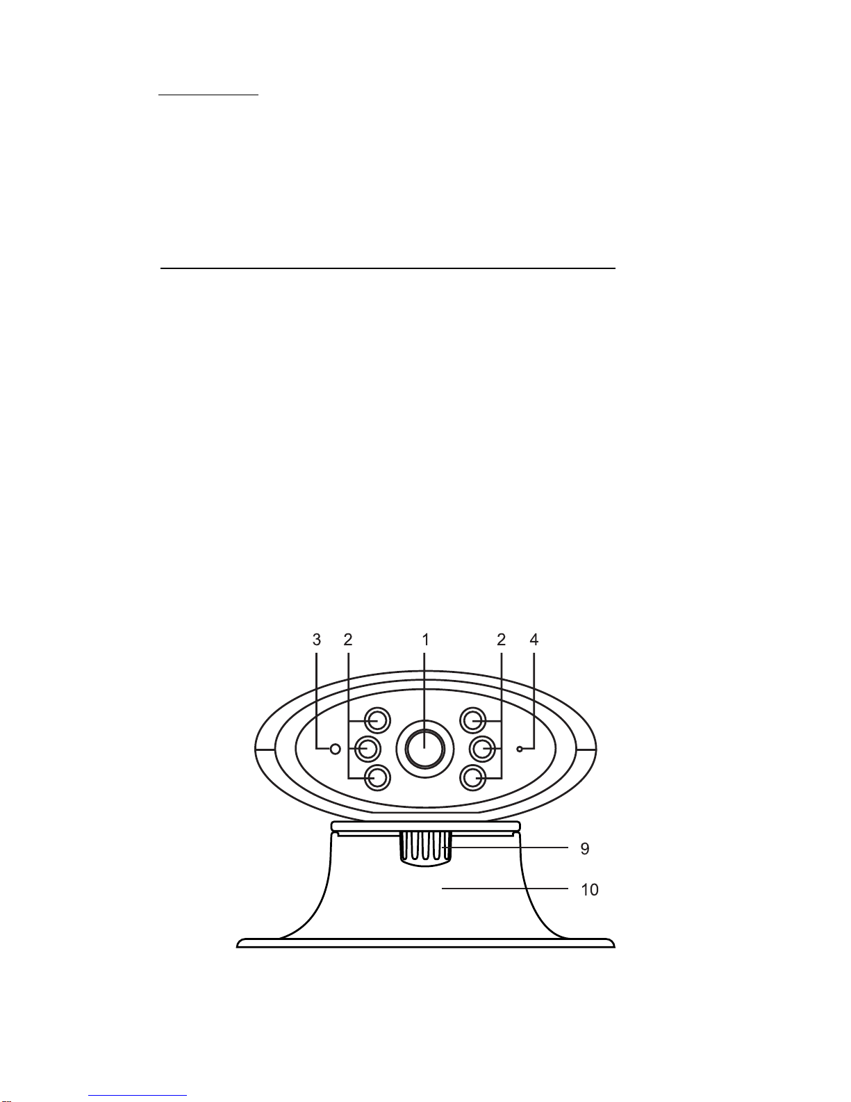
D. Controls/Jacks/Indicators (Figures 1 & 2)
1. Camera Lens
2. Infrared LEDs
3. Power LED indicator
4. Microphone
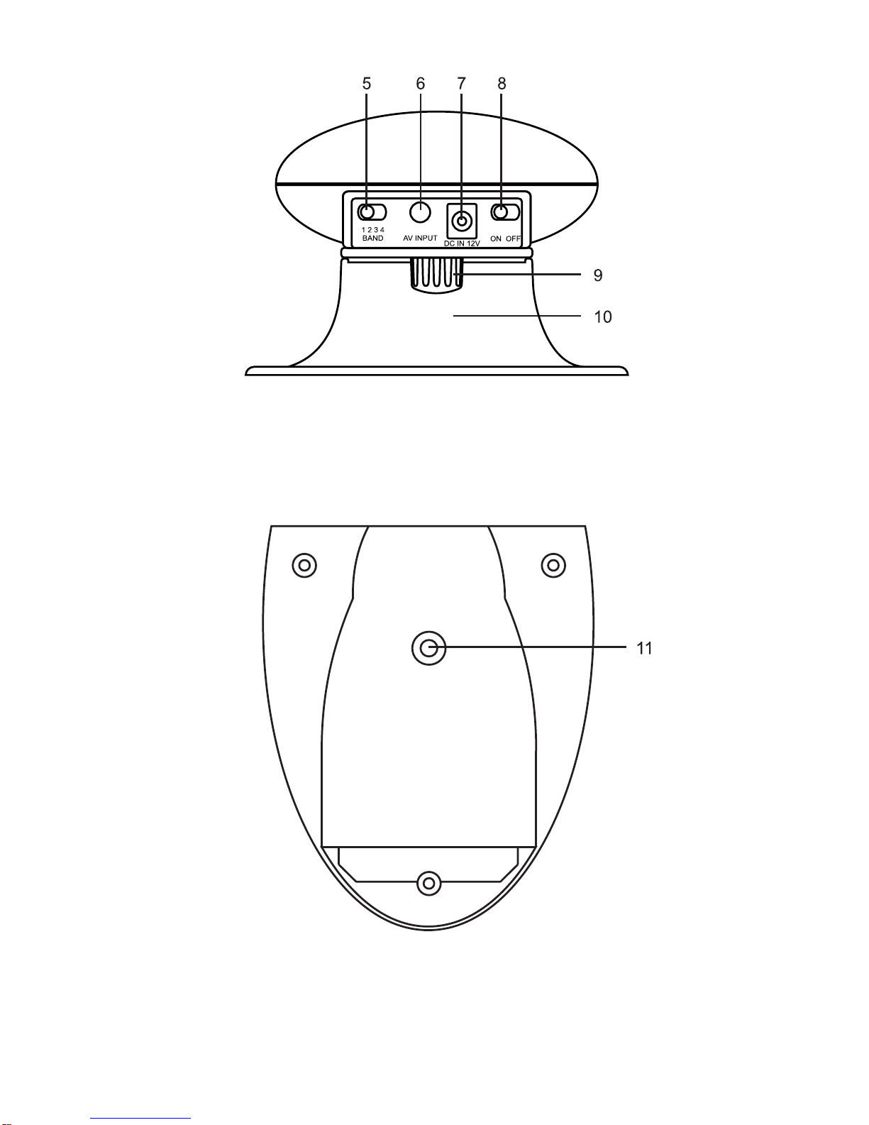
5. Channel selector Switch
6. AV Input Jack
7. DC 12V Input Jack
8. Power On/Off Switch
9. Mounting Thumb Screw
10. Mounting Base
11. Mounting Hole
FIG.1
FRONTVIEW
6
FIG.2
BACKVIEW
FIG.3
BOTTOMVIEW

E. Installation
Attach the bottom of the camera to the mounting base
using the provided thumbscrew (Fig.3). Select the lo-
cation for the camera (transmitter) NOTE: The location
must be within 100 feet of the monitor (receiver) Place
the camera in your selected location. You can attach
the camera to walls or other flat surfaces by the use of
screws (two holes provided, screws not included),
double sided tape or fastening method.
F. External Signal Sources Input
Besides the built-in camera as a signal source, there
is anAV Input Jack on the transmitter for external signal
source such as DVD Player, Video Cassette Player,
game console, etc.
G. Camera Setup
1. Make sure the transmitter and receiver are set at
the same channel (1, 2, 3 or 4). The channel can
be customized corresponding to any signal source.
With the channel switch, the receiver can receive
the 2.4GHz wireless audio/video signals from up
to 4 cameras (transmitters) in order to monitor a
series of rooms for maximum supervision of the
home (or office).
2. Connect the AC adapter to the camera and switch
the transmitter ON.
3. Adjust the angle and focus for the camera lens for
best image.
7

H. Block Diagram
I. Operational Description
XMC-151/ACN-3560C wireless transmitter module intended
for in 2.4GHz wirelessA/V signal Sender and Receive set as
RF output modulator, which converts the FM video and au-
dio signal into the RF signal for TV or Monitor. This device
have a built–in antenna but without ground system. And this
device can also be seemed as a portable device with the
monitor and can use within 100 feet indoor or 300 feet if
without obstruction. You can fixed the device on a table or
wall by screwed the mounting base. To fix the device, please
follow the installation. And please make sure the supervi-
sion and monitor are set at the same band before in use.
8

9
J. Specifications:
Video System
Transmitter Frequency
Max Range
Transmitter Antenna
Transmitter Sensitivity
Picture of Color
Optical Size
Effective Pixels
Auto Exposure
Camera Correction
Backlight Compensation
Indoor/ Outdoor
Mic Sensitivity
Number of Channels
Modulation duty cycles
Frequency Control
Video Input Level
Differential Gain
Audio Input Impedance
A/V Signal Level Ratio
Output RF Level
Video Input Impedance
Video Modulation
Differential Phase
Audio Modulation
Power Consumption
NTSC
2.4~2.83GHz
300 feet
Directional
0dBm FCC
B/W
1/3”
320 X 240
1/60~1/6000 second
Auto
Auto
Indoor Only
2~3 Meters
4
7:3
IIC PLL
1 Vp-p
+ 8%
1.4K Ω
27dB
50mW
1.3 K Ω
3MHz
+ 8%
40KHz
DC12V 300mA

NOTE: This equipment has been tested and found to com-
ply with the limits for a Class B digital device, pursuant to
Part 15 of the FCC Rules. These limits are designed to
provide reasonable protection against harmful interference
in a residential installation. This equipment generates, uses
and can radiate radio frequency energy and, if not installed
and used in accordance with the instructions, may cause
harmful interference to radio communications. However,
there is no guarantee that interference will not occur in a
particular installation. If this equipment does cause harmful
interference to radio or television reception, which can be
determined by turning the equipment off and on, the user is
encouraged to try to correct the interference by one or more
of the following measures:
Reorient or relocate the receiving antenna.
Increase the separation between the equipment and
receiver.
Connect the equipment into an outlet on a circuit different
from that to which the receiver is connected.
Consult the dealer or an experienced radio/TV technician
for help.
10
Table of contents


