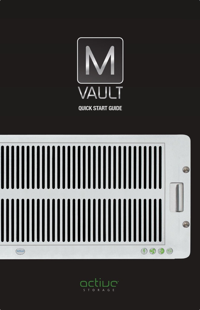
Active Storage mRAID16 User manual

mRAID16
Quickstart Guide

Installation Process
Initializing the Storage System
connections
(Optional) Connecting ground
cables
Connecting mRAID16 expansions
Connecting to a terminal
A generic view of cable
Checking installation tools
Installing guide rails
Installing storage system
into the cabinet
Installing a cable tray
Installing a disk module
Connecting power cables
Checking circuit breakers
Checking components
Connecting Cables
2 People
Required
Installation Preparations
Checking system installation
Checking cable connections
Checking
Hardware Installation
(Optional) Installing Host Software
Switching on external
power supplies
Pressing the power button
Powering On the
Storage System
on mRAID16
Checking status indicators

2a
Installing guide rails
lT
he
adjustable
guide
rails
are
600
mm
(23.62
in.)
to
900
mm
(35.43
in.)
long.
lT
he
adjustable
guide
rails
are
preconfigured
with
positioning
pins
applicable
to
square
holes
only.
For
round
holes,
replace
the
positioning pins.
lT
wo
paired
adjustable
guide
rails
must
be
positioned
exactly
parallel
to
one
another.
Attaching adjustable guide rails for mRAID16
Rear
Front
Attaching adjustable guide rails for mRAID16 Expansion
Rear
Front

Installing bearing guide rails for mVault75
(1) Pull out the inner rail of the ball bearing guide rails. (2) Remove a rail support.
Left guide rail
Right guide rail
(3) Loosen the screws and adjust the length of the ball
bearing guide rail to be the same as the cabinet depth. (4) Install the ball bearing guide rails.

(5) Fasten screws. (6) Install a ball bearing guide rail bracket.
(7) Check the installation of the ball bearing guide rails.
Check the distance between the left and right guide rails, and
ensure that the two templates can snatch into the ball bearing
guide rails.
Check that the ball of the ball bearing guide rail has been
placed at the most front end of the middle rail.
Check that the edges of the middle rail and external rail are
on the same vertical plane.

2b Installing storage systems into the cabinet
NOTICE
l Do not stack components. Install them on guide rails.
l If you remove controllers and disks to facilitate a move, record the location of each component and its slot in
advance to help when inserting each component back to its correct slot.
l If the controller is inserted into a different location, a system power-on failure may occur.
Installing mRAID16 and mRAID16 Expansion
Install mRAID16 Expansion on the guide rails
using the same method as installing the
mRAID16.
Installing mVault75
(1) Install the inner rail. (3) Install a cover.
(2) Mount the mVault75.
Place the side step at (4) Install the mVault75.
the rear of the system
to the front bracket of
the bear ball guide rail.
Slide the system
horizontally into the
cabinet (the inner rail
and middle rail will be
automatically pushed
into place).
When mounting the mVault75, place the side step in the rear of the mVault75 on the front bracket of the ball
bearing guide rails, and slide the mVault75 in the cabinet along the ball bearing guide rails (no manual
alignment is required because the inner rail automatically connects to the middle rail).

2c Installing a cable tray
(1) Insert the cable tray into the ball bearing guide rails and the mVault75.
(2) Use a Phillips screwdriver to fasten M6 screws and secure the cable tray.
(3) Install the spring pins to cable trays to secure the cable tray.

2d Installing a disk module
Figure (1)
Figure (2)
When installing the disk drive module, refer to step 3 and step 4 in figure (1).

3 Connecting Cables
3a A generic view of cable connections on the mRAID16
3b (Optional) Connecting ground cables
Application
server
mRAID16
expansion
Terminal
External
power
External
power
mRAID16
Connecting ground cables for mVault75.

3c
Connecting expansions
lAll the EXP ports on the mRAID16 can connect only to the PRI ports. An incorrect connection will cause a
service interruption.
lFor mEAID16 with two or more mRAID16 Expansions, set up multiple loops based on the number of expansion
ports on the mRAID16, and evenly allocate those mRAID Expansions to the loops.
lConnect mRAID16 Expansions in one loop over two separate links for optimal network reliability.
Connecting mRAID16 Expansions
mRAID16
Controller A
Controller B
mRAID16
Expansion 2
Expansion
module B
Expansion
module A
mRAID16
Expansion 1

Connecting mVault75
l Connect two mVault75s using mini SAS HD electrical cables. The cables must be naturally bent and a minimum of
4” clearance must be reserved in front of each mVault75 for winding cables.
l mRAID16 Expansion and mVault75 cannot be connected to one expansion loop.
l Each expansion loop of mVault75 must be connected to two adjacent ports (excluding ports P1 and P2) of the 12
Gbit/s SAS interface module on a mRAID16, for example, ports P0 and P1 or ports P2 and P3.
Controller A
Controller B mRAID16
mVault75 3
Expansion Expansion
module B module A
mVault75 2
mVault75 1

3d
Connecting to a terminal
l After connecting a serial port on the storage system to the terminal, you can then manage and maintain the storage
system.
l During initial configuration, set an IP address for the management network port through the serial port.
3e Connecting power cables
Terminal
mRAID16
mRAID16
Expansion
NOTICE
To ensure a high availability of the mRAID16 and to avoid unexpected power failure, connect the mRAID16 to two
routes of power supplies.
Scenario 1 Connecting an AC power cable
Complete view of the AC power cables
External power
External power
mRAID16

4 Checking Hardware Installation
4a
Checking system installation
Check Item
Normal
Abnormal
mRAID16
lThe system sits stably on the guide rails
without displacement.
lScrews are properly secured.
lThe system slants or cannot be detected.
lScrews are loose or have fallen off.
mRAID 16
Expansion
4b Checking cable connections
lFollow the correct power-on sequence: Turn on the external power supplies (mRAID16 Expansions first and then
mRAID16s).
-
Press the power buttons on the mRAID16s.
-
Turn on the FC switch.
-
Turn on the application
servers.
lFollow the correct power-off sequence: Stop host services.
-
Press and hold down the power buttons on the
mRAID16s until it is completely powered off (five seconds).
-
Disconnect the mRAID16s and the mRAID16
Expansionsfromtheirpowersupplies.
5a Switching on external power supplies
Turn on external power supplies in the following sequence:
mRAID16 Expansions -+ mRAID16 -+ FC switches (for a SAN) -+ application servers.
Ground cable, optical fiber
cable, mini SAS HD
electrical cable/optical cable, The cable is fully inserted and secured.
network cable, and serial
cable
lThe AC power cables for each mRAID16 or
mRAID16 Expansion are connected to two
The cable is loose or disconnected.
AC power cable separate power supplies for redundancy.
lThe AC power cables are secured with plastic
buckles.
lThe AC power cables for each mRAID16 or
expansion are connected to the same power
supply.
lThe AC power cables are not secured with
plastic buckles.
5 Powering On the mRAID16 and mRAID16 Expansion
NOTICE
lTo avoid electric shocks, do not wear an ESD wrist strap when the mRAID16 is powering on.
lDo not adjust mini SAS HD electrical cable/optical cable connections between mRAID16 and mRAID16
Expansion after power-on.
The power-on process requires 5-15 minutes. Then the mRAID16 Expansions start power-on automatically.
Turning on the switches of the power distribution box
Rear
Front
Turning on the switch of the PDU
Front
Rear

5b Pressing the power button on mRAID16
5c Checking status indicators on the mRAID16 and expansions
mRAID16
NOTICE
After you have powered on a mRAID16 expansion or the mRAID16, check that all disks are working correctly
(no alarm/location indicator is steady red).
mRAID16
Alarm indicator of the
mRAID16: off
Power indicator of the mRAID16:
steady green
Expansion
Alarm indicator of the
mRAID16 expansion: off
Power indicator of the
mRAID16 expansion:
steady green

6 Initializing the mRAID16
After you have powered on the mRAID16, complete the following initialization steps:
1.
Log in to the ActiveManager on the maintenance terminal using the IP address of the management network port.
2.
Follow the Settings > Initial Configuration wizard to change the basic information, configure the system time, disk domain,
alarm notification and import license files.
7 Configuring the mRAID16
For system configuration, please download the mRAID16 Quick Configuration Guide for SAN or NAS from the
“Documents” section of our web site http://active-storage.com.
mVault75
Alarm indicator of the
mVault75: off
Power indicator of the
mVaullt75 : steady green
lThe default user name and password of the mRAID16 are admin and Active@active respectively.
lThe command to change password is change user password.
Table of contents
Other Active Storage Storage manuals
Popular Storage manuals by other brands
OWC
OWC U.2 SHUTTLE Assembly manual and user guide

IBM
IBM T400 Setup, operation, and service guide
Western Digital
Western Digital WD10000H1CS-00 - Home Edition Quick install guide

Hama
Hama Highspeed FlashPen Floater USB 2.0 Operating instruction

Omega Lift Equipment
Omega Lift Equipment 46000 Operating instructions & parts manual

Buffalo
Buffalo MiniStation HD-PXTU2 user manual


