actuant Mastervolt SunMaster CS15TL RP Operating manual

SunMaster
CS15TL RP / CS20TL RP / CS30TL RP
HIGH POWER GRID CONNECTED SOLAR INVERTER
UK | USERS AND INSTALLATION MANUAL | P01
NL | GEBRUIKERS- EN INSTALLATIEHANDLEIDING | P45
DE | BEDIENUNGS- UND INSTALLATIONSANLEITUNG | P93
FR | MANUEL UTILISATEURS ET D’INSTALLATION | P141
ES | MANUAL DEL USUARIO Y DE INSTALACIÓN | P189
IT | MANUALE DI USO E MANUTENZIONE | P237
10000000186/04

02|EN / SunMaster CS15TL RP / CS20TL RP / CS30TL RP

OVERVIEW CS15TL RP/ CS20TL RP/ CS30TL RP
Figure 0-1: Overview of the SunMaster CS15TL RP / CS20TL RP / CS30TL RP
1. 3-phase 400V grid connection
2. Fan module (air inlet)
3. Communication module
4. External grounding (PE) facility
5. Multi-language display
6. Solar input 1
7. Solar input 2
8. Foot stands
9. Air outlets
|03
EN / SunMaster CS15TL RP / CS20TL RP / CS30TL RP

CONTENT
1 GENERAL INFORMATION 6
1.1 PRODUCT DESCRIPTION 6
1.2 USE OF THIS MANUAL 6
1.3 VALIDITY OF THIS MANUAL 6
1.4 SCOPE OF GUARANTEE 6
1.5 LIABILITY 6
1.6 CHANGES TO THE INVERTER 6
1.7 IDENTIFICATION LABEL 6
2 SAFETY GUIDELINES AND WARNINGS 7
2.1 WARNINGS AND SYMBOLS 7
2.2 USE FOR INTENDED PURPOSE 7
2.3 INSTALLATION, MAINTENANCE, REPAIR 7
2.4 WARNING OF SPECIAL DANGERS 7
3 HOW IT WORKS 8
3.1 PV MODULE, STRING, ARRAY AND COMBINER BOX 8
3.2 GRID CONNECTED INVERTER 8
3.3 NON-ISOLATED (TRANSFORMERLESS) 8
3.4 GRID INTERFACE 8
3.5 DISPLAY AND MONITORING 9
3.6 INGRESS PROTECTION AND OPTIMA COOLING 9
3.7 ANTI ISLANDING 9
3.8 STABIGRID FUNCTION 9
3.9 REACTIVE POWER 9
4 BEFORE YOU START 10
4.1 TRANSPORT, LIFTING AND STORAGE 10
4.2 INSTALLATION ENVIRONMENT 10
4.3 DC INPUT SPECIFICATIONS 10
4.4 SOLAR ARRAY CAPACITANCE 11
4.5 AC OUTPUT SPECIFICATIONS 12
4.6 LIGHTNING PROTECTION 12
5 GENERAL INSTALLATION AND COMMISSIONING 13
5.1 THINGS YOU NEED FOR INSTALLATION 13
5.2 UNPACKING THE CS INVERTER 13
5.3 MOUNTING THE INVERTER 14
5.4 AC 3-PHASE CONNECTOR 14
5.6 CONNECTING AND COMMISSIONING 15
6 OPERATION AND MAINTENANCE 16
6.1 GENERAL 16
6.2 MAINTENANCE 16
6.3 DE-COMMISSIONING 16
7 COMMUNICATION 17
7.1 COMMUNICATION MODULE 17
7.2 MASTERBUS NETWORK 17
7.3 MASTERBUS CONNECTORS 17
7.4 RS485 CONNECTORS 18
7.5 REMOTE MONITORING WITH RS485 18
7.6 PLANT TOTALS 18
7.7 ALARM CONTACTS 18
04|EN / SunMaster CS15TL RP / CS20TL RP / CS30TL RP
10000000186/04 March 2013

|05
EN / SunMaster CS15TL RP / CS20TL RP / CS30TL RP
8 DISPLAY 19
8.1 BUTTONS 19
8.2 THE HOME SCREEN 19
8.3 MAIN MENU 19
8.4 ENERGY TOTALS 19
8.5 PLANT TOTALS 20
8.6 MULTIMETER & STRINGMASTER 21
8.7 DATALOGGER 22
8.8 LOGBOOK 23
8.9 CONFIGURATION MENU 23
9 SPECIFIC DC CONFIGURATIONS 28
9.1 ISOLATION DETECTION 28
9.2 USING A STRINGMASTER PRO 28
9.3 DC SWITCH 28
10 SPECIFIC AC CONFIGURATIONS 29
10.1 SUPPORTED COUNTRIES 29
10.2 FUNCTION TEST FOR ITALIAN INSTALLATIONS 29
10.3 ACTIVE POWER MANAGEMENT 31
10.4 REACTIVE POWER EXPLANATION 32
10.5 REACTIVE POWER MANAGEMENT 32
10.6 USING AN ISOLATION TRANSFORMER 33
11 FUNCTIONAL GROUNDING 35
11.1 FUNCTIONAL GROUNDING 35
11.2 INSTALLATION REQUIREMENTS 35
11.3 INVERTER SETTINGS 35
11.4 MULTIPLE CS INVERTERS ON A
SINGLE TRANSFORMER 35
12 TROUBLE SHOOTING 36
12.1 LED INDICATION AND SOLUTION TABLE 36
13 TECHNICAL SPECIFICATIONS 37
13.1 OUTLINE DRAWINGS 38
14 ORDERING INFORMATION 39
15 CERTIFICATES 40
15.1 VDE0126-1-1 CERTIFICATE OF COMPLIANCE 40
15.2 RD 1699 COMPLIANCE 41
15.3 ENEL CERTIFICATE 42
15.4 BDEW CERTIFICATE 43
15.5 EC DECLARATION OF CONFORMITY 44
1 GENERAL INFORMATION
1.1 PRODUCT DESCRIPTION
The SunMaster CS15TL, CS20TL and CS30TL, further
referred to as “SunMaster CS” or “CS inverter” are grid
connected solar inverters. This inverter type is used to
convert photovoltaic power and feed this into a three phase
grid. The CS inverter is not suitable for stand-alone use
(i.e. use without utility grid).
1.2 USE OF THIS MANUAL
Copyright © 2013 Mastervolt. All rights reserved.
Reproduction, transfer, distribution or storage of part or all of
the contents in this document in any form without the prior
written permission of Mastervolt is prohibited.
This manual serves as a guideline for the safe and effective
use and installation of the SunMaster CS:
• For the installer this manual gives directions for the
installation, operation and commissioning.
• For the end user, this manual gives directions for the operation, maintenance and possible correction of minor
malfunctions of the CS inverter.
• Every person who works with the apparatus should be familiar with the contents of this manual, and must
carefully follow the instructions contained herein.
• Store the manual in an accessible place.1.3 VALIDITY OF THIS MANUAL
This manual is valid for the following models:
Part no Model
131210150 SunMaster CS15TL RP
131210200 SunMaster CS20TL RP
131210300 SunMaster CS30TL RP
All the specifications, provisions and instructions contained
in this manual apply solely to the Mastervolt-delivered stand-
ard version of the CS inverter.
1.4 SCOPE OF GUARANTEE
Mastervolt assures the product guarantee of the SunMaster
CS during five years after your purchase, on the condition
that all instructions and warnings given in this manual are
taken into account during installation and operation. Among other things, this means that installation is carried
out by a qualified electrician, that installation and mainte-
nance are executed according to the stated instructions and
correct working sequence, and that no changes or repairs may have been performed on the CS inverter other than by
Mastervolt.
The warranty is limited to the costs of repair and/or replace-
ment of the product by Mastervolt only. Costs for installation
labour or shipping of the defective parts are not covered by
this warranty.
For making an appeal on warranty you can contact your supplier directly, stating your complaint, application, date of
purchase and part number / serial number.
1.5 LIABILITY
Mastervolt accepts no liability for:
• consequential damage due to use of the SunMaster CS; • possible errors in the manuals and the results thereof.1.6 CHANGES TO THE INVERTER
Changes to the SunMaster CS hardware are not allowed.
Changes to the SunMaster CS software/ firmware, except
for the settings made available to the user or installer, are not
allowed.
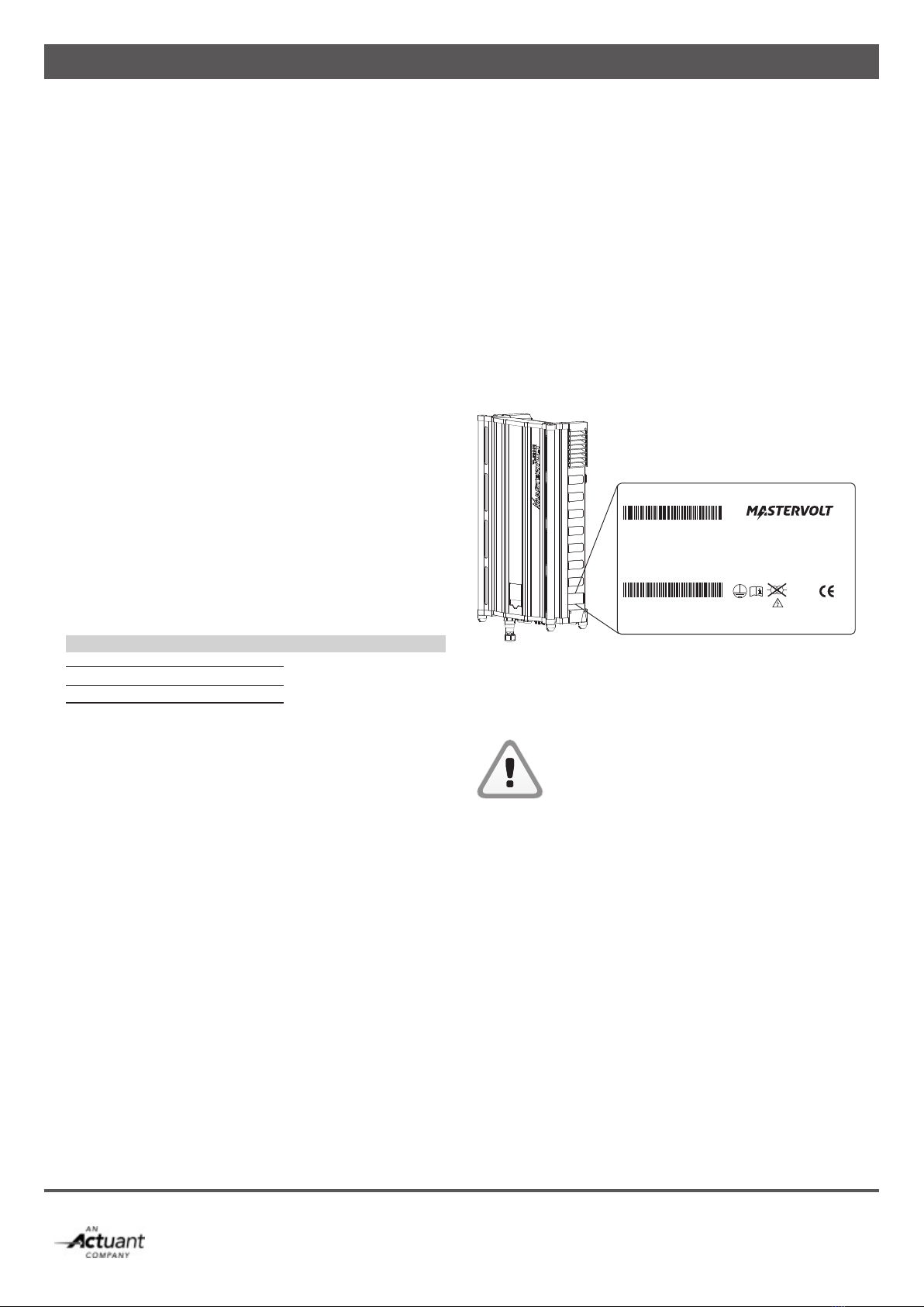
1.7 IDENTIFICATION LABEL
Figure 1-1
The identification label is positioned at the right side of the
CS inverter, see figure 1-1.
CAUTION!
Never remove the identification label.
06|EN / SunMaster CS15TL RP / CS20TL RP / CS30TL RP
Part no : 131210200
Type : CS20TL RP
Input : 200-980Vdc, 1000Vdc Max
: MPP 350-800Vdc, 2x30A
Output : 400/230Vac, 3ph/N/PE, 50/60Hz,
: 32Amax, 20kVAnom
: cos φ 0.85 ind - 0.85 cap
VDE 0126-1-1
VDE AR-N-4105
ENEL GCR Ed. 2.1
G59/2-1
RD1663
SYNERGRID C10-11
Serial no: X402-0007 Made in PRC
IP65
CAT III 1000V
2 SAFETY GUIDELINES AND WARNINGS
2.1 WARNINGS AND SYMBOLS
Safety instructions and warnings are marked in this manual by the following pictograms:
A procedure, circumstance, etc which
deserves extra attention.
CAUTION!
Special information, commands and
prohibitions in order to prevent damage.
WARNING
A WARNING refers to possible injury to
the user or installer or significant material
damage to the inverter if the installer / user
does not (carefully) follow the stated
procedures.
2.2 USE FOR INTENDED PURPOSE
The SunMaster CS is constructed as per the applicable
safety-technical guidelines. Use the CS inverter only in
installations that meet the following qualifications:
• in permanent installations; • connected to a separate, grounded three phase AC group, to which no other electrical equipment is connected;• the electrical installation must meet the applicable
regulations and standards (must be carried out correctly)
and must be in a good condition;• according to the technical specications as stated
in section 10.1.
WARNING
Never use the SunMaster CS in situations
where there is danger of gas or dust explosion
or potentially flammable products!
Use of the inverter other than as mentioned under section 2.2
is considered to be conflicting with the intended purpose.
In such cases, Mastervolt will not accept liability for any
damage or injury caused by the functioning or malfunctioning
of the inverter.
2.3 INSTALLATION, MAINTENANCE, REPAIR
WARNING
As dangerous voltages exist, only allow
installation, maintenance and repair of the
SunMaster CS to be carried out by
qualified electricians.
Connections and safety features must be executed according
to the locally applicable regulations.
In case of decommissioning and/or demounting follow the
instructions as stated in section 6.3.
If repairs or replacements are required, only use original
Mastervolt spare parts.
2.4 WARNING OF SPECIAL DANGERS
Two primary energy sources are present:
• solar panels (DC) • utility grid (AC).Switch off both sources before starting any
work on the installation. Block the switching device against unintentional reconnection.
Verify the de-energizing of both DC and AC
connections using a suitable metering
instrument.
The voltages present at the grid and solar side
of the CS inverter are not safe to touch.
Make sure two persons are present when working on the installation, at least until the installation has been de-energized and verified
by a suitable metering instrument.
|07
EN / SunMaster CS15TL RP / CS20TL RP / CS30TL RP

3 HOW IT WORKS
The CS inverter is a grid connected photovoltaic power
inverter. It converts the high voltage DC power coming from
the photovoltaïc (PV) panels into AC power. The AC voltage
is fed back into the public utility grid.A series of PV panels is called a string. One string can be
connected to one solar input of the inverter.
Figure 3-1: Schematic example of the CS inverter in a PV plant
3.1 PV MODULE, STRING, ARRAY AND COMBINER BOX
PhotoVoltaïc (PV) modules convert light into DC power. To
reduce cable losses, PV modules are connected in series: a
so-called “string”. A plane of PV modules is called a PV ar-
ray and consists of multiple strings of the same length, being
connected in parallel. PV strings can be paralleled in a string
(combiner) box. These boxes may provide over current
protection and/ or over voltage (surge) protection, DC
isolating switch and string monitoring functionality.
3.2 GRID CONNECTED INVERTER
See figure 3-1.
The SunMaster CS main task is to convert DC power
produced by the PV modules into AC power and to feed it
back into the public utility grid. The SunMaster CS is not
suitable to be operated in stand-alone mode (independently
from the utility grid). The SunMaster CS has two
independent DC inputs. The PV arrays connected to these
inputs are each operated at their optimum voltage for an
optimal yield (MPP tracking).3.3 NON-ISOLATED (TRANSFORMERLESS)
The SunMaster CS is a non-isolated (transformerless)
inverter. During operation, it couples the PV array potential to
the utility grid. An optional isolating transformer is available
for applications where galvanic isolation is required
(functional grounding, see chapter 11).
3.4 GRID INTERFACE
The DC PV input is inverted to an AC output: 230/400V AC
(3-Ph/N/PE) output in Wye (Y) configuration. For the PV input
operating voltage range refer to the specifications.
Anti- islanding is provided according to national standards.
The grid interface contains numerous safety mechanisms to
guarantee a level of safety better than an isolated inverter.
Redundant relays isolate the inverter from the grid in case
one of the following circuits detects a fault:
Isolation resistance detection: monitors PV array isolation
resistance.
• RCMU (residual current monitoring unit): monitors and protects against ground leakage currents. • DC injection: Monitors DC current injection into the grid. • Grid voltage- and frequency monitoring• Anti islanding protection: loss of utility detection• Low voltage ride through• Reactive Power08|EN / SunMaster CS15TL RP / CS20TL RP / CS30TL RP
DC power
Stringbox CS Inverter
AC power

3.5 DISPLAY AND MONITORING
3.5.1 CS inverter display
The CS inverter is equipped with a multi language display
for on site monitoring and control. Refer to chapter 8
Display for details.
3.5.2 Remote monitoring via RS485
The SunMaster CS supports RS485. This bus facilitates
remote monitoring via the RS485 network using a
DataControl datalogger. Monitoring can be accomplished via
internet or via a telephone connection. See also section 7.4.
If you opt for remote Monitoring & Control, please contact
your Mastervolt supplier.
3.5.3 Remote monitoring and control via MasterBus
The CS inverter can communicate with an optional
StringMaster and isolation transformer via the
MasterBus network.3.6 INGRESS PROTECTION AND OPTIMA COOLING
The SunMaster CS consists of two separate compartments.
Rubber seals provide IP65 protection of the power
electronics against ingress of dust and humidity. The
cooling compartment provides IP44 protection and contains
only components resistant to dust and humidity. By keeping the inverter cool, the intelligent Optima Cooling algorithm
helps to reduce losses and extend inverter life.
3.7 ANTI ISLANDING
The SunMaster CS is equipped with an anti-islanding system
that ensures instant disconnection in case of grid failure.
European countries maintain different regulations with
regard to anti-islanding devices and grid connection of
distributed generation in general. The common islanding
device switches off the inverter if the grid voltage or
frequency is out of range. The CS inverter is set to
local regulations by setting the country in the configurations
menu. This setting is password protected. The password is
available for installers on request.
CAUTION!
NEVER connect the CS inverter to a utility
grid other than specified, refer to section 4.5.
3.8 STABIGRID FUNCTION
SunMaster CS inverters have a high level of immunity to
voltage fluctuations caused by industrial loads. The inverter
stays online in case of minor grid fluctuations, thereby
supporting the utility network and increasing the daily
energy yield.
3.9 REACTIVE POWER
As per January 1st 2012, PV installations in Germany
capable of generating more than 3,68 kVA will be required to provide reactive power.
Reactive power is used by the utility operators to control the
voltages in the power grid. As the share of power
generated by PV installations grows every year, it becomes
increasingly important for PV plants to support the grid similar
to conventional power plants.
The SunMaster CS “RP” version has been developed to
meet the new requirements according to the new VDE-
AR-4105 norm. The specific features required in this norm
will
automatically be enabled when the installation country
“Germany” is selected:
• Active Power Derating; which can be self-controlled by the inverter depending on the grid frequency, or set by
the grid operator via telecommand.
• Reactive Power Provision; which can be self controlled by the inverter, depending on different variables (grid voltage
or inverter output power)
Active grid support functions limit the capacity of active
power and therefore should be taken into account when
designing a PV system. Mastervolt provides a “SysCalc”
design tool to assist customers with system design work.
It is available for free on www.mastervoltsolar.com. Refer to
section 10.4 for more information on Reactive Power.
|09
EN / SunMaster CS15TL RP / CS20TL RP / CS30TL RP
10|EN / SunMaster CS15TL RP / CS20TL RP / CS30TL RP
4 BEFORE YOU START
4.1 TRANSPORT, LIFTING AND STORAGE
Ensure adequate and secure packaging during transportation of the CS inverter. Always use
suitable handling equipment for transportation.
More than two persons may be required to
hang the CS inverter to a wall, refer to local
safety standards.
The CS inverter is shipped in a wooden crate that can be
handled with a fork lift. In order to prevent damage, always transport the CS inverter in its transportation crate. Minimum
two persons are required to unpack the CS inverter and to lift it out of its box.
4.2 INSTALLATION ENVIRONMENT
The CS inverter is designed for both indoor and outdoor use,
protection degree is IP65.
Operating conditions:
• -20 to 60°C, relative humidity 4% to 100% condensing. • Power derating at temperatures above 45 °C.• Start-up at temperatures above -10 °CCAUTION!
Do not install in aggressive environments like ammonium, acids and salt air.
CAUTION!
Do not install in areas that are subject to the
risk of gas- or dust explosions.4.2.1 For all installations
• If the CS inverter is installed in the immediate vicinity of living areas, take into account that it can produce a certain noise level when operating.
• Hang the CS vertically to a sufciently strong, solid wall, no other angle other than straight up is allowed.
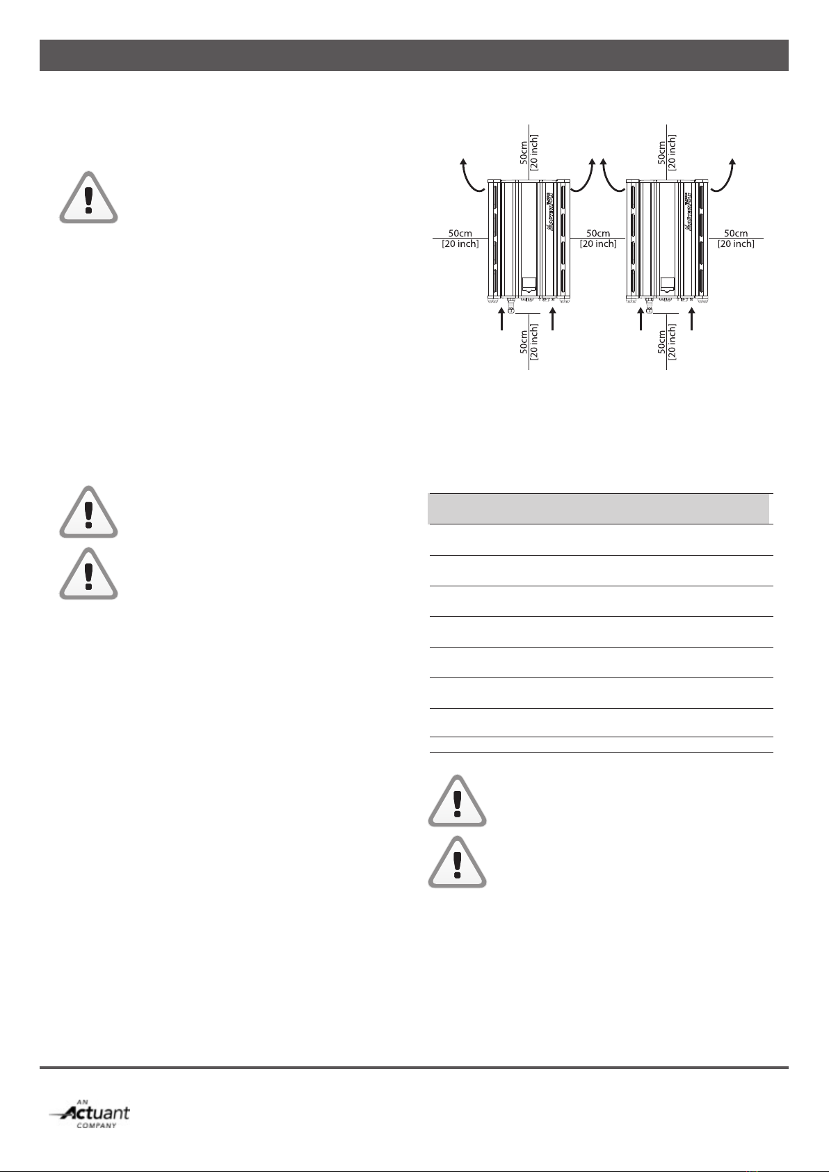
• Keeping at least 50 cm space around the CS inverter is recommended, see fig. 4-1.
4.2.2 For indoor installations
• Maintain sufcient ventilation and enough distance around each inverter to prevent build up of hot air.
4.2.3 For outdoor installations
• Prevent placement in direct sunlight as this warms up the inverter, resulting in performance loss.
• Shield the inverter against direct rain when possible to avoid corrosion.
• In humid atmospheres with large temperature differences, moisture may gather behind the display screen. If this
persists, contact your Mastervolt supplier.
Figure 4-1: Mounting distance
4.3 DC INPUT SPECIFICATIONS
The PV installation to which the inverter is connected should
meet the following input specifications.
DC Input specifications per input
Model CS15TL RP CS20TL RP CS30TLRP
Absolute max. 1000VDC 1000VDC 1000VDC
Input Voltage
Operating 200VDC – 980VDC
voltage
Full power 350VDC – 350VDC – 460VDC –
voltage 800VDC 800VDC 800VDC
Max. input 23ADC 30ADC 34ADC
current
Maximum 9,5 kWp 12,5 kWp 19,0 kWp PV power
Recommended 9,0 kWp 11,5 kWp 17,5 kWp PV power
Maximum array 6 µF total for 2 inputs
capacitance
Max. PV ISC 30A 30A 34A
Never connect voltages higher than 1000V DC
to the inverter, as this will cause permanent
damage to the inverter.
The inverter will automatically limit the input
current and power to its specified rating. Excess
power will not be converted.
Air inlet Air inletAir inlet
Air outlet Air outletAir outlet

|11
EN / SunMaster CS15TL RP / CS20TL RP / CS30TL RP
4.3.1 Recommended cabling
All devices within the PV installation (panels, wiring, terminal
blocks, fuse holders, fuses, switches, etc.) must be rated for the applicable maximum voltage and current ratings.
Use double isolated DC cabling for all connections.
A sufficiently large copper cross section will help reducing
the cable losses.
Current 10ADC 20 ADC 30ADC
Length
<10 m 2.5 mm24.0 mm26.0 mm2
10-20 m 4.0 mm26.0 mm210 mm2*
>20 m >4.0 mm2>6.0 mm2* >10 mm2*
*Cable adapter may be necessary for cross sections >6.0 mm2
4.3.2 DC Connectors and switch
The SunMaster CS inverters use MC4 compatible DC
connectors with a 4 mm pin diameter.
Do not reverse the polarity of the PV
connections. The inverter will be permanently
damaged, and large short-circuit currents
may occur.
For safety reasons, the use of a suitable DC switch between
the PV modules and the inverter is recommended.
Depending on locally applicable regulations, such a switch
may be mandatory.
4.3.3 Parallel or independent operation
The SunMaster CS has two independently controlled inputs,
labelled “Input 1” and “Input 2”. These inputs can be used as
separate inputs or they can be connected in parallel depend-
ing on the PV installation. The inverter will automatically detect
if the inputs have been paralleled. Make sure to divide the PV power over the two inputs as equally as possible.
Parallel operation Independent operation
For uneven number of Per input different array
strings in the array. configuration or orientation
possible.
Required when applying Reduce losses in case of local
functional grounding. shadowing.
Refer to chapter 11.
To accommodate more than 1 PV string on each input, a DC
combiner box such as StringMaster should be used. Refer to
the StringMaster manual for specific installation instructions.
When more than three strings are paralleled in an array, they
must be fused. Use only DC rated fuses with appropriate
voltage and current ratings.
To avoid excessive losses, always make sure the string
voltages are equal to each other before paralleling them.
Never use different string lengths or different module types
in the same array.
Figure 4-2: Parallel and independent operation
Figure 4-3: Functional scheme StringMaster
4.4 SOLAR ARRAY CAPACITANCE
Every solar panel has a small parasitic (virtual) capacitance
between the photo-sensitive material and the external
structure. In the PV array all these capacitances add up to
one larger (virtual) capacitance.
If this capacitance is too large, it causes a high leakage current to flow from the main electrical path to the external
structure. Such currents can be dangerous to humans and
may further degrade the performance of the installation.
< 3 strings > 3 strings
U U
Fuses
DC
Switch
Surge
protection
CS15TL
CS20TL
CS30TL
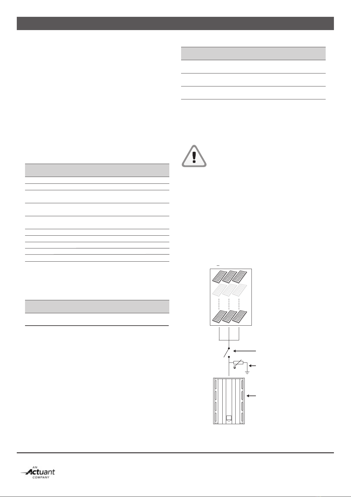
12|EN / SunMaster CS15TL RP / CS20TL RP / CS30TL RP
< 3 strings
U
Inverter
DC Switch
Surge protection
PV array
The SunMaster CS is designed to operate with a solar ar-
ray capacitance up to 6 µF. Larger array capacitances may
cause too large leakage currents, and can trip the internal RCD protection.
If the RCD trips because of large PV array capacitance,
installing an isolation transformer may be necessary. Consult
your Mastervolt distributor for assistance.
4.5 AC OUTPUT SPECIFICATIONS
The SunMaster CS is intended for use in a permanent
installation, connected to a separately fused three-phase
AC branch to which no other equipment is connected. All
electrical connections must comply with locally applicable
installation codes and regulations.
The CS inverter is designed to operate in the following grid
conditions:
AC specifications
Model CS15TL RP CS20TL RP CS30TL RP
Nominal Power 15.000VA 20.000VA 30.000VA
Maximum Power 15.750VA 21.000VA 31.500VA
AC Voltage 3 Phase - 4 Wire Y
UGRID = 230VRMS +20%/–20%Max. Phase
Current 3 x 24,2 ARMS 3 x 32,2 ARMS 3 x 46 ARMS
Max. Neutral
Current <1 ARMS
AC Frequency (50Hz) 45Hz – 55Hz
AC Frequency (60Hz) 55Hz – 65Hz
Max. Inrush Current 28.2A
Short circuit L-N 150A peak/12.9A RMS(3 cycl) during 8msShort circuit L-L 298A peak/21.8A RMS (3 cycl) during 4ms
4.5.1 Fusing
The SunMaster CS does not have internal fuses. External
fuses or circuit breakers are mandatory on every phase
according to the following ratings:
AC fuses
Model CS15TL RP CS20TL RP CS30TL RP
Fuse B
Characteristic 32A 40A 63A
Not installing a properly rated fuse (Icu > 2.1 kA) will pose a safety hazard and will void the warranty of the inverter.
4.5.2 Wiring
The AC output is arranged in a 230/400V AC (3-Ph/N/PE)
Wye configuration. The neutral connection does not carry
any current, but must be connected to the inverter. The PE
connection must have a cross section as large as the largest
line conductor used, with a minimum of 4 mm2. For easy
installation, using a flexible cable type is recommended.
Refer to the locally applicable installation codes and
regulations for cable sizing.
AC wiring
Model CS15TL RP CS20TL RP CS30TL RP
Minimum cable
cross section 4 mm26 mm210 mm2
Maximum AC
connector capacity 10 mm216 mm2
Flexible cable
outer diameter 20 mm 25 mm
4.5.3 RCD
The SunMaster CS is equipped with an internal RCD, refer to
specifications for tripping values. If an external RCD is used,
Mastervolt advises to use A, B, or AC sensitive devices with
a trip current of at least 300 mA.
CAUTION!
If you use RCD’s in your installation, connect
maximum one CS inverter to an RCD
4.6 LIGHTNING PROTECTION
In a solar installation, precautions must be taken to avoid damage from surges induced by lightning. The CS inverter
is equipped with class III (micro) protection devices against
over voltages on all DC, AC and communication
connections. Additional external surge protection and use of
flexible cable is strongly recommended. StringMaster string
boxes feature class II surge protectors and are available from
Mastervolt. When used, surge protectors must be installed
less than 10m away from the inverter.
Figure 4-4: Surge protection in a PV installation

|13
EN / SunMaster CS15TL RP / CS20TL RP / CS30TL RP
This chapter describes the general installation of one single
inverter. For example, specific installations with more than
one inverter and transformers are explained in chapter
9 and 10.
CAUTION
At least until all components have been verified
to be de-energized, 2 persons are required
during installation.
CAUTION!
Read chapters 2 and 4 prior to installation.
WARNING
High voltages (up to 1000 VDC) may exist on
the PV strings! Switch off the solar voltage and
verify that no dangerous voltage is present, be
fore starting the cable work. Use suitable
testing equipment
CAUTION!
Short circuiting, miswiring or reverse polarity
may lead to damage to the CS inverter, the
cabling and/or the terminal connections.
Follow all steps of the installation instructions
in order of succession as described.
5.1 THINGS YOU NEED FOR INSTALLATION
Make sure you have all the parts you need to install the
CS inverter:
• 1 CS inverter (included)• 1 mounting bracket (included)• 1 AC 3-phase output plug (included)• String combiner box like the StringMaster or the
Switchmaster. • 2 MasterBus terminating devices (included)• This user’s and installation manual (included) • M6 bolts and plugs to x the CS enclosure to the wall. Use mounting materials that are suitable for the application.
• Tools for wall mounting• Tools to connect, AC, DC and communication wiring• A suitable multimeter5.2 UNPACKING THE CS INVERTER
The CS inverter is packed in a plastic bag and delivered in a special transport box, refer to figure 5-2.
1. Cut open the card board box with a sharp knife. 2. Remove manual and bracket and take away the cover.3. Cut the tie wraps and lift the inverter from the box.
The inverter can be put on its four foot stands before
hanging it to the wall. Take care not to bend parts of
the enclosure.
Figure 5-1: Foot stands
After unpacking, check the contents for possible damage. Do not use a damaged
product. If in doubt, contact your supplier.
Figure 5-2: Unpacking
5 GENERAL INSTALLATION AND COMMISSIONING

14|EN / SunMaster CS15TL RP / CS20TL RP / CS30TL RP
5.3 MOUNTING THE INVERTER
Fix the CS inverter to the wall, starting with the mounting
bracket. See gure 5-3. Use suitable screws and plugs.Figure 5-3: Drilling dimensions of bracket and display
After hanging the SunMaster CS to the bracket, secure the enclosure to the wall using the fixing plate. See figure 5-4.
Figure 5-4: Fixing plate
Figure 5-5: Bottom view of the SunMaster CS connections
See figure 5-5.
AC connector: refer to section 5.4,
Communication module: refer to chapter 7,
PV input: refer to section 4.3.
5.4 AC 3-PHASE CONNECTOR
The AC connector has five wire terminals, figure 5-6 shows
the connector. Connect PE first (yellow-green). On the
CS30TL connector, the PE terminal is located at the bottom
when the two white markings at the other side of the connector are facing upwards.
Protective Earth
1. Line 1 (L1)
2. Line 2 (L2)
3. Line 3 (L3)
4. Neutral (N)
Figure 5-6:
AC 3-phase connector for CS15TL RP and CS20TL RP (left) and for
CS30TL RP (right)
A ground stud has been provided, see figure 5-7.
Figure 5-7: Ground stud
5.5 DC CONNECTORS
The DC connectors on the SunMaster CS are compatible
with connectors of the MC 4 type.
105M6 4,13
188 7,41 270 10,6
323 12,73
272 10,7
80 3,15
592,49 23,33
488 19,21
125 4,92
AC
Communication
module
PV input

|15
EN / SunMaster CS15TL RP / CS20TL RP / CS30TL RP
5.6 CONNECTING AND COMMISSIONING
To check the correct operation of the CS inverter,
commissioning should be carried out during daytime only.
Follow these steps to switch On the SunMaster CS:
1 Connect the earth cable to the ground stud.
2 Check AC and DC cabling and connectors. 3 Connect the AC cables.
4 Connect the DC cables.
5 If applicable, switch on the AC grid.
6 Move the DC switch (if applied) of the solar array
to the ON position.
5.6.1 Language and country selection
Until the CS inverter is configured in
accordance with the local regulations for grid
connection, it will stay in standby mode. This
means that no power will be converted.
Figure 5-8: Select language
1 Select the language, using the display. This setting is
found under Configuration/ Display settings/ Language.
Figure 5-9: Select country
2 Select the country, using the display. This setting is found
under Configuration/ Grid interface/ Country.
Figure 5-10: Set date and time
3 Set the day and time.
4 Check the PV input DC voltage. Check the AC voltage at the grid side of the AC circuit breaker using the display multimeter menu (see section 8.6). The AC voltages
should be:
L1 - N 230V AC +/- 10% L2 - N 230V AC +/- 10% L3 - N 230V AC +/- 10%If DC and AC voltages are within range and
solar irradiation is sufficient, the CS inverter will
switch on automatically. This may take a
few minutes.
16|EN / SunMaster CS15TL RP / CS20TL RP / CS30TL RP
6 OPERATION AND MAINTENANCE
This chapter describes the operation of one single inverter.
6.1 GENERAL
After installation and commissioning the CS inverter will
switch on automatically if solar irradiation is sufficient. The
CS inverter operates automatically: there is no need to
operate it manually. If the irradiation of the PV modules is
insufficient, for instance at night, the CS inverter switches
off automatically. The LCD screen however stays operational
as long as AC power is available. No live measurements are
available in this situation.
6.2 MAINTENANCE
Switch off the DC switch before any
maintenance takes place!6.2.1 Cleaning
Cleaning of the CS inverter enclosure is not necessary under
normal circumstances. If cleaning is still preferable, use a
soft damp cloth to clean the enclosure of the CS inverter.
Never use any aggressive or abrasive cleaning agents. Use
of high pressure cleaning equipment is prohibited as it may
damage the sealing.
High Pressure cleaning of the Sumaster CS
is not allowed!
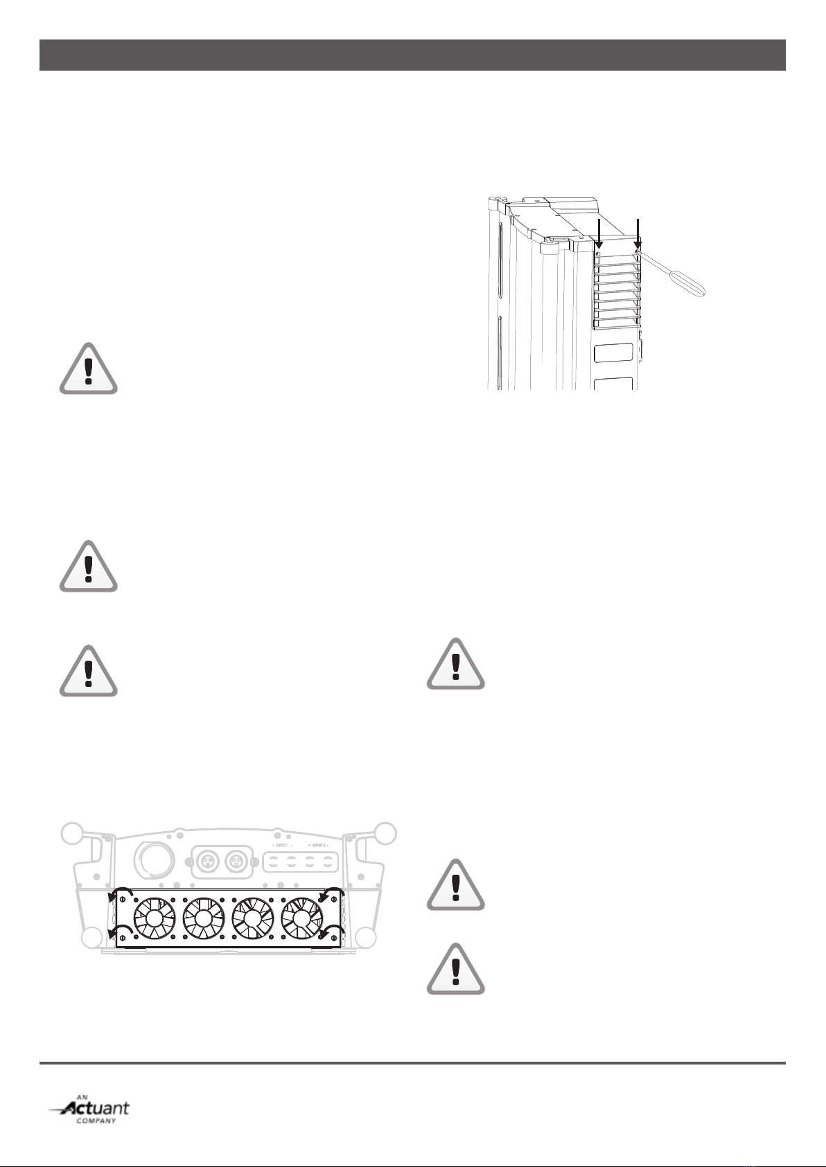
6.2.2 Fan module
Only remove the fan module when the CS
inverter is switched off.
The fan module (gure 6-1) needs checking and cleaning every 12 months, in dusty environments checking is needed more often. Unscrew the 4 hand screws as indicated.
Carefully move out the fan module, bottom first and unplug
the four fans before removing the module completely. If
necessary, clean the fans using compressed air.
Figure 6-1: Fan module with hand screws
6.2.3 Air outlet
The CS inverter is provided with wire mesh behind the air
outlets (fig. 6-2).
Figure 6-2: Removing the air outlets
Remove the two air outlets by unscrewing the two Phillips
screws on top. Clean if necessary.
6.2.4 Electrical connections
Have your electrical installation checked by a
qualified installer at least once a year. Defects such as
loose connections, burnt wiring etc. must be corrected
immediately.
6.3 DE-COMMISSIONING
If it is necessary to put the CS inverter out of operation,
follow the instructions in order of succession as
described below:
CAUTION!
Follow below mentioned instructions in order
of succession as described.
1 Switch Off the DC switch
2 Cut off the grid voltage by switching off the AC
circuit breaker3 Release the AC connector
4 Release the DC connectors. A special tool may be needed
to release the DC connectors.
5 Disconnect the ground (PE) connection
Now the SunMaster CS can be demounted in a safe way.
CAUTION!
Never release the DC plugs during operation
of the CS inverter. A spark or an electric arc may develop, in which case both plug and
socket of the CS inverter must be replaced.CAUTION!
Be sure to disconnect all other cables before
disconnecting PE.

|17
EN / SunMaster CS15TL RP / CS20TL RP / CS30TL RP
7 COMMUNICATION
7.1 COMMUNICATION MODULE
The CS inverter is equipped with a detachable communication
module (drawer) for inserting the MasterBus and RS485 plugs.
It also facilitates mounting the alarm wiring.
Figure 7-1: Communication module
Install the communication wiring, see the steps below:
• Loosen the Phillips screws at both sides of the front plate (see figure 7-1).
• Pull out the module, taking care not to damage the
connectors and components.
• Release glands and remove plugs where applicable.• Insert the connectors and mount the alarm wiring.
See the label in figure 7-2 for more information.
Figure 7-2: Communication label
MasterBus connectors are similar to RS485
connectors! Wrong installation causes
communication failure.
7.2 MASTERBUS NETWORK
All devices that are suitable for MasterBus are marked by the MasterBus symbol.
MasterBus is a fully decentralized data network for
communication between the different Mastervolt system
devices. The communication network is based on CAN-bus which has proven a reliable bus-system. New devices can be
added to the existing network by just extending the network. This gives the MasterBus network a high degree of exibility for extended system configuration. Mastervolt also offers
several interfaces, making even non-MasterBus devices
suitable to operate in the MasterBus network.CAUTION:
Never connect a non-MasterBus device to the
MasterBus network directly! This will void
warranty of all MasterBus devices connected.
7.3 MASTERBUS CONNECTORS
The CS inverter is equipped with 2 x 2 MasterBus connec-
tors (A and B) to install two MasterBus networks. Network A is reserved for the string box or a transformer
connected to the CS inverter. The other network (B) is
reserved for communication and updating the inverter.
Figure 7-3: MasterBus network example
Proceed as follows to remount the communication module:
• Close any unused holes in the glands, using the
premounted caps.
• Insert communication module, using the guidance rails.• Fix the Phillips screws at both sides of the front plate
(see figure 7-1).
For MasterBus connection of the CS-IT20
isolation transformer, refer to section 6.5.3.
Install the communication cables separated
from the AC and DC cables to prevent
communication loss caused by interference!
7.3.1 How to set up a communication network
Every device that is suitable for the RS 485 and MasterBus
network is equipped with two data ports. When two or more devices are connected using these ports, together they form
a local data network.NO
NC
COM
COMMUNICATION
A
Max 30V/1A
ALARM
CONTACT
!
B
485
485
Mastervolt
StringMaster COM
NO
NC
!
!
COM
NO
NC
Max 30V/1A A B
485
485
485
485
Max 30V/1A
Mastervolt
StringMaster
USB
Interface

18|EN / SunMaster CS15TL RP / CS20TL RP / CS30TL RP
Figure 7-4
7.4 RS485 CONNECTORS
The two connectors in the centre of the connection blockare RS485 connectors. They can be used for connecting up to 20
CS inverters. They also connect your inverter to an optional
Datalogger. We recommend not to make a ringnetwork or
T-connections in your RS485 network. The maximum network length is 1000m.
Connections between the devices are made by standard
straight UTP cables. Mastervolt can supply these cables.
These cables are also commonly available at computer
supply stores.
Figure 7-5
7.5 REMOTE MONITORING WITH RS485
Mastervolt provides several monitoring solutions like PC software, dataloggers, remote monitoring and so on.
Consult www.mastervoltsolar.com for a comprehensive
overview of all possibilities.
Figure 7-6: RS485 connections
7.6 PLANT TOTALS
RS 485 connection of the inverters also enables display
of the plant totals. These are the power totals, calculated
by adding the individual powers of all connected inverters.
Refer to section 8.5.1.
7.7 ALARM CONTACTS
See figure 7-7, left part. The three alarm contacts (maximum
load 30V/1A) are Common (Com), Normally Open (NO) and
Normally Closed NC), see figure 7-7. Refer to section 8.9.5
for alarm contact settings.
Figure 7-7: Alarm contacts schematic example
Max 30V/1A
ALARM
CONTACT
+_
NO
NC
COM
!

|19
EN / SunMaster CS15TL RP / CS20TL RP / CS30TL RP
8 DISPLAY
The SunMaster CS is fitted with a multi-lingual graphic
display allowing to view operational data and access all
setting parameters. It also provides access to plant data
and StringMaster Pro measurements when connected in the
installation.
8.1 BUTTONS
The CS inverter dislay has six buttons and a two-colour LED,
refer to figure 8-1.
Figure 8-1: Display, buttons and LED
8.2 THE HOME SCREEN
The default screen shown in the display is the Home Screen.
It is presented in figure 8-2. If no buttons have been pushed
for some time, the inverter automatically returns to this
screen. The Home Screen shows a summary of the actual
inverter status, warning and error messages and additional
information if available.
Figure 8-2: Home screen
a. Current date
b. Inverter ID
c. Current time
d. Today’s power generation
e. Inverter status, error messages and warnings
f. StringMaster status and messages or Plant
Totals information
g. Current output power
h. Energy generated today
In case an alarm occurs, it will appear on the screen.
8.3 MAIN MENU
Pushing the BACK button allows to switch back and forth between the Home Screen and the Main Menu. The Main
Menu, shown in figure 8-3, is the starting point to access all
inverter information and settings.
Figure 8-3: Main menu
The Main Menu shows 6 icons. Select one of the icons using
the Navigation buttons and press OK to enter one of the
following menus:
1. Energy Totals. Total power generated since
first commissioning.
2. Plant Totals. Actual measurements and status info of all
inverters connected in the PV plant.
3. Multi Meter. Detailed measurements of this inverter and
the connected StringMaster.
4. Data Logger. History of power and energy generated by
this inverter.
5. Logbook. History of error and warning messages
for this inverter.
6. Config. Access to the settings menu.
The BACK button has the display return to the
Home Screen
8.4 ENERGY TOTALS
The Energy Totals screen (see figure 8-4) shows the total
power generated by this inverter since its commissioning
to date, the related financial savings and the CO2emissions
that have been avoided with this renewable energy source.

20|EN / SunMaster CS15TL RP / CS20TL RP / CS30TL RP
Figure 8-4: Energy totals
The BACK button has the display return to the Main Menu.
8.5 PLANT TOTALS
If multiple CS inverters have been connected to each other
via RS485 cables, the Plant Totals function screen will
collect information from all connected inverters and show
a summary on the display. Refer to section 7.6 for more
information on how to set up the PV plant with Plant Totals
functionality. The Plant Totals function is split into 4 different
screens, shown in figures below.
8.5.1 Plant Totals – Overview
The Plant Totals (PT) Overview screen shows a bar graph
summarizing the performance of the entire PV plant. Each
bar represents the actual* AC power output of one inverter.
In case a particular inverter has an error, an exclamation
symbol is shown instead of the power bar.
See figure 8-5. Below each bar, each inverter is referenced
with a number. This number corresponds with the inverter
number used in the next Plant Totals screens.
In the bottom of the screen, the actual* sum of all power
generated by the plant is shown. Pushing the BACK
button has the display return to the Home Screen.
Pushing the LEFT or RIGHT navigation button will scroll to
the previous/next Plant Totals screen.
* Due to delays in the communication line and a limited
update frequency, the power figures shown in the plant to-
tals screens may differ from the information presented
on that particular inverter.
Figure 8-5: Plant Totals screens 1
Figure 8-6: Plant Totals screens 2
8.5.2 Plant Totals – Inverter Information
The performance of each inverter in the plant is further
detailed in the Inverter Info screens. By using the LEFT and
RIGHT Navigation buttons, the information table can be
shifted to the left or right. The following information is
available for each inverter:
Figure 8-7: Plant Totals Info 1
Figure 8-8: Plant Totals Info 2
This manual suits for next models
2
Table of contents
Popular Inverter manuals by other brands

Progressive Dynamics
Progressive Dynamics PD1200 Series Quick reference guide

Goodwe
Goodwe TURBO ENERGY Lithium Series Quick installation guide

Sealey
Sealey MW140.V2 instructions

Projecta
Projecta IMW300 manual

SMA
SMA SUNNY HIGHPOWER PEAK3 Quick reference guide

Steca
Steca StecaGrid 8 000+ 3ph Installation and operating instructions

IVT
IVT SC 10A operating instructions

Mitsubishi Electric
Mitsubishi Electric FR-A520-0.4K-NA instruction manual

Battery Supplies
Battery Supplies AQ-TRON SOL/AQT1H3M1 user guide

Jntech
Jntech JNF1KLF-A/24V user manual

Victron energy
Victron energy VE.Net Blue Power Panel manual

Honeywell
Honeywell HW750PI owner's manual


