AD Klima Fan Coil Unit Specification sheet

Fan Coil Unit
Operation and Installation Manual
One-Way Cassette Fan Coil
2 Pipe System FC02, 03, 04, 05
*Please read this manual before using the fan coil.
*Please keep this manual for future use

Fan Coil Unit One-Way Cassette Type
1
Table of Contents
1.Safety and User Information………………………………02
2.Product Introduction………………………………………05
3.Controller operation………………………………………...10
4.Dimensions, Weight and Wiring diagram……………….12
5.Installation………………………………………………….14
6.Commissioning……………………………………………22
7.Maintenance and Troubleshooting…………………….24
Note:
All illustrations and contents in this manual are provided for information only. We will continuously
improve the products in aspects of product dimensions, performances, materials and structures
without prior notification.

FanCoilUnitOne-WayCassetteType
2
1. Safety and User Information
1.1 Safety instructions
The One-Way Cassette fan coil units are developed and manufactured in accordance with the
state-of-the-art technological standards and established technical safety norms and regulations.
The One-Way Cassette fan coil units comply with the Machinery Safety Directive.
The One-Way Cassette fan coil units are reliable and satisfy high quality standards. This product
range combines advanced technology with a high level of user friendliness and ease of
maintenance.
However, all fan coil units inevitably pose residual risks of injury to the user or third parties or
material damage to the unit or other objects. For this reason, you should take into account and
follow all safety instructions. Ignoring these safety instructions is connected with risks to your health
and safety, can lead to the environmental damage and/or extensive material damage.
Observing the safety instructions in the operation manual will help you to avoid risks, ensure
economical operation of the unit and enjoy full benefits of the product.
The safety aspects covered by this chapter are valid for the entire operation manual. To ensure
your own safety consider the following safety instructions.
THE SAFETY INSTRUCTIONS AFTER LABLE
‘’ IS CONSIDERED AS WARNING WHICH
MEANS INCORRECT OPERATION MAY RESULT
IN SEVERE CONSEQUENCES OF DEALTH OR
SERIOUS INJURIES!
ELECTRICAL HAZARD!
Before carrying out any work on the unit, power the unit down to avoid injury from electrical current.
Check that the unit is isolated and ensure that the appropriate point of the unit for the on-site
power supply is secured against being switched back on.
DANGER OF SCALDING!
Before performing work on the valves or the inlet or outlet pipes, seal off the heating or cooling
water inlet to prevent scalding. Do not commence work before the heating water has cooled down.
DANGER OF ROTATING UNIT PARTS!
Rotating fan wheels can cause injury! Before performing any work on the unit, ensure that it is
powered down. Ensure that the appropriate point of the unit for the on-site power supply is
secured against being switched back on.

FanCoilUnitOne-WayCassetteType
3
DANGER OF OVERHEAD LOADS!
Wear a helmet and safety boots to prevent injury from falling components, especially when fitting
the unit to the ceiling. Ceiling installations should always be performed by two people.
PERSONAL INJURY!
Always wear protective gloves when moving or fitting the unit to avoid injury from sharp edges.
1.2 Important notes
The fan coil units are end units of chilled/hot water air conditioning system featuring high
profession and high technological requirement, therefore, the unit shall be installed, operated and
maintained only by qualified, specially trained and authorized staff.
1.2.1 Proper use
One-Way Cassette fan coil units are exclusively designed for heating, filtering and cooling
purposes. Chilled water/Hot water may be used as the medium. The following limit values
apply to the chilled/hot water for operating Cu/Al heat exchangers:
Unit Value
pH value (at 20 °C) 7,5 – 9
Conductivity (at 20 °C) μS/cm < 700
Oxygen content O2mg/l < 0,1
Total hardness °dH 1 – 15
Dissolved sulphur Snot detectable
Sodium Na+mg/l < 100
Iron Fe2+, Fe3+ mg/l < 0,1
Manganese Mn2+ mg/l < 0,05
Ammonium content NH4+mg/l < 0,1
Chloride Cl-mg/l < 100
Sulphate SO42- mg/l < 50
Nitrite NO2-mg/l < 50
Nitrate NO3-mg/l < 50
DAMAGE TO THE UNIT!
On open systems (e.g. when using well water observe the limit values stated in above table), the
used water should additionally be cleansed of suspended matter using a filter which should be
located at the inlet. Otherwise there is a risk of erosion by suspended matter.
You also have to ensure that the unit is protected from dust and other substances that can cause
acidic or alkaline reaction when combined with water (aluminum corrosion).
–The One-Way Cassette fan coil units may only be used indoors.
–The One-Way Cassette fan coil units can also be fitted into an intermediate ceiling.
The unit is considered to be used in a proper manner if it is applied for other purposes or a
purpose that is not covered by the scope of the given operation manual. The manufacturer or

FanCoilUnitOne-WayCassetteType
4
supplier is not liable for any resulting damage: the user alone bears the full risk.
The user is responsible for proper use. Proper use also stipulates the observance of the operation
manual and the inspection and maintenance conditions defined by the manufactures.
1.2.2 Improper use
The One-Way Cassette fan coil may not be operated:
- For treatment of outside air,
- In locations where there is a risk of explosion
- In wet areas or
- In locations with high dust levels or aggressive air.
PERSONAL INJURY & MATERIAL DAMAGE!
Improper use can cause personal injury and material damage.

FanCoilUnitOne-WayCassetteType
5
2. Product Introduction
2.1 Features and benefits
Space saving
One-Way Cassette fan coil maximize utilization of room space with recessed ceiling installation.
Compact design as unit height only 235mm, easy for installtion.
Stylish design
Newly stylish and elegant design is in harmony with top interior decoration requirement.
High efficiency
Round and optimized engineering designed coils enables the most effective energy exchanging.
Healthy Fresh Air
Much more fresh air by utilizing high efficiency synthetic fiber washable filter. (optional)
Effectiveness
One-Way Cassette fan coil units guarantee cosy and comfortable room atmosphere.
One-Way air blowing and wide angle flapping guarantees average energy diffusion.
Quietness
Newly designed pressure-stable centrifugal fan ensures the lowest operation noise.
Cost effectiveness
One-Way Cassette fan coil units have become the effective standard solution in many and various
industrial segments for comfortable economical air conditioning.
Profitability
One-Way Cassette fan coil units operate with low maintenance and follow-up costs.
2.2 Nomenclature
2.3 Operating limits
Unit and heat exchanger Values
Max. operating pressure 1.4 MPa (14 bar)
Max./Min. water temperature 75 °C / 2°C
Operating voltage 220~230V AC (50Hz or 60Hz) **[Refer to nameplate]
Power consumption/protectionclass *[Refer to nameplate]
Product Type:
CAS: Cassette One-Way
CAD: Cassette Two-Way
CAQ: Cassette Four-Way
CAX: Cassette Six-Way
Coil Layout:
2: 2 Pipes (or omitted)
Power Supply
1=220~230V/50Hz/1 Ph
2=220~230V/60Hz/1 Ph
5=115V/60Hz/1 Ph
Air Flow:
×100 CFM
Fan Coil
FC 02 CAS 2 / 1

FanCoilUnitOne-WayCassetteType
6
DAMAGE TO THE UNIT!
Please refer to unit name plate to know the right power supply! Wrong power supply may
damage the motor and unit permanently!
2.4 Unit Components
1.Cover
2.Drain pan
3.Coil left hook
4.Coil right hook
5.Drain pump
6.pumpfixtrue
7.Coil
8.Inlet water pipe assembly
9.Water purge
10.Outlet water pipe assembly
11.Coil join plate
12.Mounting brackers
13.Left side plate
14.Fan motor hook
15.Control box cover
16.Control board
17.Transformer
18.Terminal blocks
19.Capacitor
20.Control box
21.Right side plate
22.Capacitor
23.Fan blower
24.Volute
25.Casing
26.Cover panel assemb
2.5 Specification

Specification Cassette 1-Way Fan Coil Unit - 2 Pipe System (CAS)
Specification FC02 FC03 FC04 FC05
CFM 200 300 400 471
m3/h 340 510 680 800
CFM 159 235 306 382
m3/h 270 400 520 650
CFM 112 176 235 294
m3/h 190 300 400 500
1.90 2.70 3.60 4.00
1.50 2.10 2.80 3.30
1.00 1.60 2.10 2.60
1.30 1.90 2.50 2.80
1.10 1.60 2.10 2.30
0.80 1.30 1.70 1.80
2.70 4.10 5.40 6.40
2.20 3.20 4.10 5.20
1.50 2.40 3.20 4.00
Power Input 45 54 62 70
Running Current 0.2 0.24 0.28 0.31
Noise Level 39/36/30 39/36/30 40/37/31 42/39/37
330 480 625 690
0.092 0.133 0.174 0.192
Water Resistance 10 15 18 20
20 20 25 35
2 3
1095*535*310
23
850*400*235
1045*465*30
Centrifugal Fan
Split Permanent Capacitor Motor
Class B
220~230V/1Ph/50 or 60Hz
Seamless copper mechanically expanded into aluminum fins
1.4 MPa
3/4" FPT
Φ25
Gross Weight
kg
Unit
Panel
Note:
1. Nominal Testing condition:
Cooling: entering air temp 27°C DB/19.5°C WB; entering water temp 7°C, leaving water temp 12°C;
Heating: entering air temp 21°C; entering water temp 60°C, the same water flow as in cooling;
2.Sound pressure level are measured in acoustic room, position of the measure point is 1.5m below the vertical center line of the unit
25.5
Packing Dimension
W/D/H mm
Unit
Panel
Net Weight
kg
Unit
Panel
Inlet/Outlet Water Pipe
Condensate Water Pipe
Net Dimension
W/D/H mm
Unit
Panel
Coil
Type
Rows
Max. Working Pressure
kPa
Fan Type
Motor
Type
Insulation Class
Power Supply (V/Ph/Hz)
Power Consumption (W)
W
A
dB(A)-H/M/L
Water Flow kg/h
l/s
Heating Capacity
kW
H
M
L
Sensible Cooling
Capacity
kW
H
M
L
Total Cooling Capacity
kW
H
M
L
Model
Air Flow
H
M
L

FanCoilUnitOne-WayCassetteType
8
2.6 Decorative panel
DANGER OF ROTATING UNIT PARTS!
Don't put fingers or any other things into the inlet/outlet and swing louver while the conditioner is in
operation, because the high speed fan is very dangerous and may cause injuries.
NOTE!
- The unit cannot be cleaned with water otherwise it may have short circuit or be destroyed.
- Remember to close the air inlet grill properly after cleaning air filter.
- Operate the unit according to instructions strictly for effective efforts. Otherwise it may cause
leakage or work abnormally.
- Please adjust indoor temperature properly, especially when there are old people, children,
and patient and so on in the house.
- Lightning and electromagnetic radiation may influence this machine. If the machine is
influenced, please cut off electric power then turn on it again.
- It is forbidden to block or cover the air outlet and inlet.
2.6.1 Panel overview
1. Remote control receiver
2. Body of panel
3. Blade
4. Air inlet grille
2.6.2 Remote receiver and LED display
a) Remote receiver:
It receives operational orders sent out by infrared remote controller. To ensure the quick and
effective operation of the unit, please operate the controller aims at remote receiver on the panel.
b) Buzzer:
It would sound ‘Bi…’ when you do any one of the following actions:
- Turn on the unit

FanCoilUnitOne-WayCassetteType
9
- Operation of remote controller and infrared signal from remote controller is correctly received.
c) LED display
When the air conditioner has malfunction, the self-diagnostic system will identify malfunction
automatically and display malfunction code. Please refer to section "Malfunction and
troubleshooting".
2.6.3 LED display sketch
LED Display:
- Green: Cooling;
- Yellow: Timer;
- Red: Heating;
- Reset: Emergency Switch.When the unit is switched off, press the reset button then the unit
will enter into cooling mode automatically; if press again the reset button then the unit will
enter into heating mode; if press again the reset button then the system will be switched off.
- Receiver: Remote receiver

FanCoilUnitOne-WayCassetteType
10
3.Controller operation
3.1 Infrared controller
On/Off
Clock
Temp
oolCyDr nFa atHe langSi
Louver
Clock
Sleep
Swing
Fan Speed
Set Temp
Operation instruction:
1. ‘On/Off’ Button
- Press On/Off button to turn on/turn off the unit.
2. TEMP 'Up' 'Down' Button
- Press 'Up' or 'Down' button to increase or decrease the temperature desired.
3. 'MODE' Button
- Select unit operation mode: Cool->Dry->Fan->Heat->Auto (both cool and heat symbol light
up)
4. 'FAN' Button
- Press 'Fan' button to select fan speed: Auto->Low->Medium->High.
5. 'FAN' Button
- Press 'Fan' button to select fan speed: Auto->Low->Medium->High.
- In Fan mode, only low, medium, high speed is available.
- In Dry mode, fan speed will not be displayed.
6. 'TIMER ON' Button
- Press the ‘TIMER ON’ button once, the previous timer setting will display on the LCD.
Slide Down
FanCoilUnitOne-WayCassetteType
11
- Press the ‘TIMER ON’ button continuously, the timer will be changed in one minute intervals
- You can hold on the ‘TIMER ON’ button to speed up the time adjusting until reaches the
desired time.
7. 'TIMER CANCEL' Button
- Press ‘TIMER CANCEL’ to cancel all the timer setting.
8. 'TIMER OFF' Button
- Press the ‘TIMER OFF’ button once, the previous timer setting will display on the LCD.
- Press the ‘TIMER OFF’ button continuously, the timer will be changed in one minute intervals
- You can hold on the ‘TIMER ON’ button to speed up the time adjusting until reaches the
desired time.
9. ‘SLIDE DOWN’ Button
- Slide down the cover in order to put in or replace the battery (1.5V).
10. ‘SWING’ Button
- Press ‘SWING’ button to turn on/turn off swing function.
11. ‘CLOCK UP’ Button
- Press ‘CLOCK UP’ button continuously for 2 seconds, then the current set time will increase 1
minute at each press.
- You can hold on the ‘CLOCK UP’ button to speed up the time adjusting until reaches the
desired time.
12. ‘CLOCK DOWN’ Button
- Press ‘CLOCK DOWN’ button continuously for 2 seconds, then the current set time will
decrease 1 minute at each press.
- You can hold on the ‘CLOCK DOWN’ button to speed up the time adjusting until reaches the
desired time.
13. ‘LOUVER’ Button
- Press ‘LOUVER’ button to select the louver position 1,2,3,4 auto, or stop.
14. ‘SLEEP’ Button
- Press ‘SLEEP’ button to activate the energy saving sleep function which will automatically
control the unit working according to the room temperature.
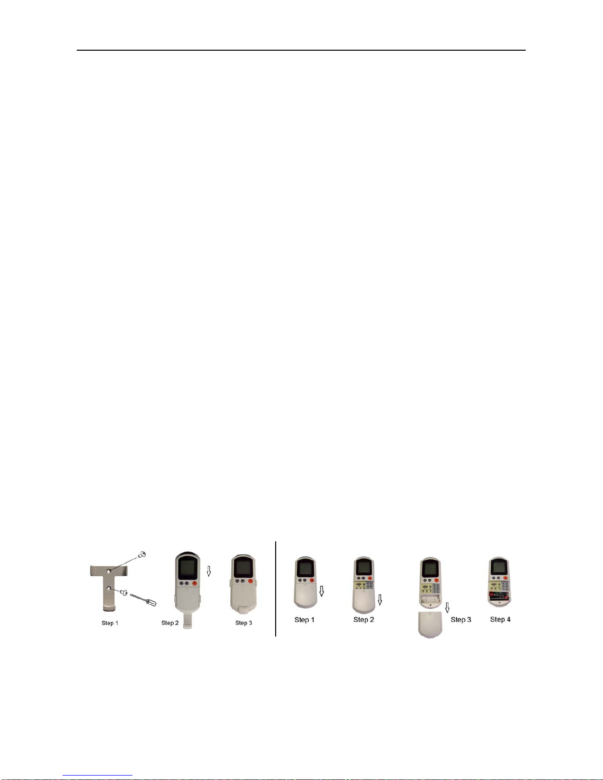
3.2 Controller Installation
Install the remote controller holder to the wall and put the battery (1.5V*2) as shown below.

FanCoilUnitOne-WayCassetteType
12
4. Dimensions, Weight and Wiring diagram
4.1 Dimensions - Model FC02/FC03/FC04/FC05
Frequently used installation data
- Unit external dimension (W*D*H): 848*394*235mm
- Panel external dimension: 1043*468*30mm
- Hanging hook position dimension: 760mm*434mm
- Ceiling open dimension: (938~993)*(414~448)mm
Other dimensions are marked in above fig.
4.2 Weight
Please refer to product nameplate or product specification sheet to know the weight of the unit.

FanCoilUnitOne-WayCassetteType
13
4.3 Wiring diagram
- Installation with motorized valve: Short-Connect connection port S6;
- Installation without motorized valve: Cut off connection port S6;

FanCoilUnitOne-WayCassetteType
14
5.Installation
5.1 Checking and acceptance
Each fan coil is packaged in corrugated cartons to avoid damages during transportation, handling
and site placement. To make sure no damages occurred due to transportation, please follow below
steps to check upon receiving the equipment:
a) Before acceptance, please check if each unit shows any abnormal facts, if carton edges and
corners are in good conditions and if there are obvious carton damages;
b) For any obvious carton damages, please immediately unpack to inspect the unit itself. If the
unit is indeed damaged, please indicate on the receipt and refuse to accept. Please also
check accessories;
c) Check hidden damages of the unit;
d) If any hidden damage is found, do not move the unit on the site. The receiver has the
obligation to evidence such damage does not occur after delivery. Meanwhile, please stop
unloading and take photos for reference;
e) If damages are found, please notify the carrier, and request the carrier and the receiver to
conduct a joint inspection;
f) Do not repair it yourself before inspection and confirmation by the carrier representative has
been made;
g) After confirmation of damages, please contact related persons for replacement.
5.2 Transport
DAMAGE TO UNIT AND PERSONAL INJURY!
- Use protective gloves to avoid injury due to sharp edges.
- Ensure that at least two people carry the fan coil to avoid injury.
- In case of deliveries on pallets, use only lifting and transport vehicles with sufficient carrying
capacity.
- Secure the load during transit to prevent it from tipping or falling.
Grasp and transport the Cassette Fan Coil using the outer casing only. Refer to below fig.

FanCoilUnitOne-WayCassetteType
15
5.3 Temporary storage
When storing the unit for a temporary period, the following points must be considered:
- Store the fan coil unit in its original packaging.
- The storage location must be weatherproof, dry and free of dust. Humidity must be between
50 and 85% r.h.
- The storage temperature must stay in the range from -10 to +50°C.
5.4 Prepare for Installation
DANGER FROM ELECTRICAL CURRENT!
- Ensure that the intended drilling area is free from electrical cables or pipes before drilling.
PERSONAL INJURY!
- Injury may be caused by falling parts and sharp edges!
- Wear a helmet, safety boots and protective gloves when installing the unit. Ceiling installations
should always be performed by two people.
NOTE!
- You must ensure that no mechanical deformations or twisting occurs during
installation of all models in all installation locations.
5.4.1 Installation location
The type, condition and ambient temperature of the installation location must be suitable for the
appropriate fan coil unit. Observe the following instructions:
- Ceiling or mounting systems must be capable of bearing the weight of the unit, including all
accessories.
- Install the unit only indoors.
5.4.2 Installation requirement
Please respect to below installation space requirement as well as ceiling requirement
a) Installation space requirement (H=235mm)

FanCoilUnitOne-WayCassetteType
16
b) Ceiling requirement
- The intermediate ceiling is installed and a corresponding opening is available for the unit.
- There may not be any openings to the outside in the area of the intermediate ceiling.
- The entire intermediate ceiling area must be dry and sufficiently protected against humidity
and moist air.
- The internal opening dimension must be within the minimum and maximum dimensions listed
in section 4.1 as ceiling opening dimension.
- The electrical wiring is prepared and is available for connection in the intermediate ceiling.
5.4.3 Recommended service opening
In order to carry out all necessary service and maintenance work on the basic unit it is
recommended that a service opening with Min. 400*400mm or larger is reserved in the false
ceiling.
5.5 Unit installation
5.5.1 Precautions
To ensure good installation and operation, do check the following items before installation of the
unit:
a) Adequate space shall be provided for installation and maintenance of the unit. Please refer to
Unit Dimensions in section 4.1. Removable ceiling panels or accesses shall be provided for
daily maintenance;
b) Determine locations of pipelines and electric wires before installation; and adequate fitting
space should be reserved.
c) Make sure hanging structure adequate to support the unit weight;
d) All units shall be leveled to ensure smooth water drain and proper operation;
e) Thermal insulation of chilled water valves and pipelines shall be made by the installer.
5.5.2 Unit mounting
a) Install a suspending bolt (M10 bolt)
To support the unit weight, anchor bolt shall be used in the case of already exists ceiling. For new
ceiling, use built-in type bolt or parts prepared in the field.
Before going on installing adjust space between ceilings.
*All above parts should be prepared in field.
b) Unit mounting
The unit is installed under the building ceiling with threaded rods to be provided by the customer.
- Determine the position of the drilled mounting holes according to the hanging hook dimension

FanCoilUnitOne-WayCassetteType
17
in section 4.1
- Provide the fixing for the threaded rods with suitable tools.
- Fasten the threaded rods to the building ceiling. The length dimensions depend on the
distance to the intermediate ceiling.
- Push the unit, with the terminal box facing front, into the intermediate ceiling at an angle, until
the unit is fully placed into the intermediate ceiling.
- Place the unit straight over the opening. Provisional fast installation is possible using the
hooks on the suspension lugs. After final positioning fix the straps to the unit wall using
tapping screws.
- Screw the unit firmly onto the threaded rods. Make sure that the unit is exactly horizontal.
5.5.3 Panel installation
NOTE!
- Check whether indoor unit is horizontal with leveler or polythene pipe filled with water,
and check that the dimension of the ceiling opening is correct. Take off the lever gauge
before install the panel.
The design panel with an air filter is not delivered pre-assembled. The required mounting material
(setscrews) is packed separately in a plastic bag.
- Loosen the air intake grille by turning each of the 2 locks.
- Remove the air intake grille. (Refer to below indication fig)
Install the panel board in the right direction, you can follow below steps.

FanCoilUnitOne-WayCassetteType
18
a) Make sure the right direction of panel in order that the installation holes on the panel is
corresponding to the unit, put two bolt in diagonal position ST4×10 and screw it but not tightly.
b) Connect wiring cable of stepping motor, display board to the elec. box and tidy up the wiring
cables.
c) Put the other two bolt in diagonal position ST4×10 and screw it to the main unit but not tightly.
d) Adjust the location and direction of panel to make air outlet frame and the drain pan wind way
acdordant.
e) Screw up the bolts tigthly and make sure the well match between unit and panel.
f) Install the air inlet grille opposite to the sequence when disamount the grille.
NOTE!
- The incorrect direction will result in water leakage, meanwhile swing and signal
receiving are displayed that cannot be connected.
- Please refer to section 5.7 before connect the cables.
- If screws are not tightening, problems in below Fig. might occur. Tighten screws
properly.
- If there is still space after tightening of screws, please readjust the height of indoor
unit.
5.6 Pipe connection
DANGER OF SCALDING BY ESCAPING
HEATING MEDIUM!
Before the on-site piping and the fan coil hydraulic connection is set up, the heating/cooling water
should be isolated and secured against being opened unintentionally.
NOTE!
- At the beginning of the fitting procedure, remove the caps on the water inlet and outlet
pipes.
- All on-site pipes by others for the cooling water must be insulated against condensate
formation.
- When all connections have been completed, all screw connections should be tightened
and checked that they are free of mechanical stress.
5.6.2 Valve connection
The units are supplied without valves, In case of installation with valves by others, the installation

FanCoilUnitOne-WayCassetteType
19
of the water inlet and outlet depends on the location of the water connection and/or the used
valves.
Below showed Fig. indicate the connection of a 2-way valve and 3-way valve to the units.
2-Wayvalve 3-Wayvalve
NOTE!
- In case of installation with motorized valve, it is necessary to short-connect the
connection port S6 on unit PCB; (If no motorized valve, then S6 should be open/cut off)
5.6.3 Water inlet/outlet pipe connection
- Connect the chilled water pipe to coil pipe by using 3/4" external thread connecter.
- Distinguish the inlet/outlet water according to the sign on the unit.
- Heat preservation must be used for the chilled water pipe, and pay attention to the end side
management of insulate material.
*Indicativefigof2pipesystem
5.6.4 Condensate water pipe connection
- Condensate pipe diameter shall be equal or larger than that of the fitxting of the unit. (Size:
20mm)
- Drain pipe should be short, with a downward slope at least 1/100 to prevent air bag from
happening.
- If downward slope can't be made, take other measures to lift it up.
- Keep a distance of 1-1.5m between suspending brackets, to make water hose straight.
Table of contents


