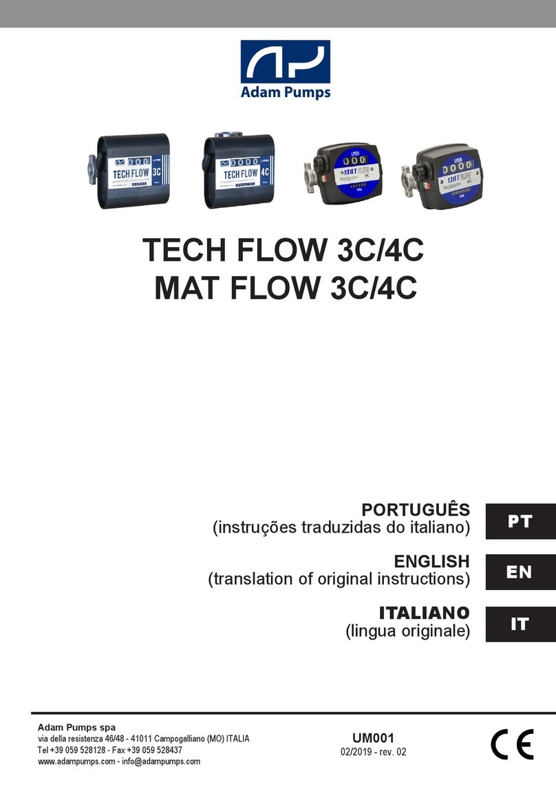
Adam Pumps DI-FLOW IN-LINE Diesel User manual

cabinets, meter, DC and AC pumps, accessories, repair kit
USE AND MAINTENANCE MANUAL
DIGITAL FLOW METER
IN-LINE
IN-LINE 12V pulses version

INDICE
0. COMPLIANCE STATEMENT
1. GENERAL ALTER
1.1 INTRODUCTION
1.2 FOREWORD
1.3 WARNINGS
1.4 GENERAL SAFETY
1.5 DISCARDING AND RECYCLING
1.6 HARMFULL EMISSON
1.7 FIRE PREVENTION
2 PRELIMINARY OPERATIONS
2.1 MANUFACTURER IDENTIFICATION DATA
2.2 MACHINE DESCRIPTIONMACHINE DESCRIPTION
2.3 ALLOWED AND FOR�IDDEN USEALLOWED AND FOR�IDDEN USE
2.4 TRASPORT AND UNPACKING
3. USE AND STARTINGUSE AND STARTING
3.1 DISPLAY ORIENTATION
3.2 CONNECTION
3.2.1 ELECTRICAL WIRING FOR PULSER
VERSION
3.3 KEY DISPLAY AND �UTTONS
3.3.1 SIM�OLS
3.4 MAIN FUNCTIONS
3.4.0 SCROLLING THROUGH 5 MAIN SCREENS
3.4.1 “PARTIAL” SCREEN
3.4.2 “TOTAL” SCREEN
3.4.3 “TOTALE PERIOD” SCREEN
3.4.4 “TANK STOCK” SCREEN
3.4.5 “MINIMUM STOCK ALARM” SCREEN
3.4.6 “LAST TRANSACTION” SCREEN
3.5 SECONDARY FUNCTIONS
3.5.1 CALI�RATION
3.5.2 INSTANTANEOUS FLOW RATE
3.5.3 SELECTING UNIT OF MEASURE
3.5.4 �UTTONS COM�INATIONS
4. MANUTENTION & STOCK
4.1 TEST LCD & �ATTERY CHANGE
4.2 CLEANING THE TUR�INE
4.3 STORAGE
4.4 DIAGNOSTIC
5. TECHNICAL DATA
6. EXPLODED VIEW AND SPARE PARTS LIST
This machine has been designed and built for INSTALLATION IN NORMAL
WORKING CONDITIONS, according to CEI standards 17-13 / 6.1. This use
and maintenance manual and related EC certification of compliance
should be considered as part of the machine, if the machine is sold they
must be handed down to new owner...
0.EC COMPLIANCE STATEMENTEC COMPLIANCE STATEMENT
ADAM PUMPS SPA
Via della Resistenza, 46/48
41011 Campogalliano (Modena) - Italy
states, taking full responsibility, that the following meter
models digital flow meter“DI-FLOW IN LINE” version
“diesel”,“AddBlue®” comply with the Directive for Safety of
Machinery: 2006/42/CEE 91/368/CEE, 93/44/CEE, 93/68/
CEE 89/336/CEE 93/68CEE 73/23CEE and the specific
EN 60529, EN 60204-1, EN 50081-2, EN 55011C/.A.
This document has been signed by:
Mr. Bernard Gilson
Via della Resistenza, 46/48
41011 Campogalliano (Modena) - Italy
Phone +39 059 528128
Fax +39 059 528437
who has full legal authority to represent the firm in the
European Community.
january 2013, 1.
ADAM PUMPS S.p.A.
1 ADAM PUMPS • DI - FLOW IN LINE
Questions?
Technical difficulties?
CALL US!
Don’t worry!
ADAM PUMPS SPA
Via della Reistenza 46/48
41011 Campogalliano
(Modena) ITALY
phone +39.059.528.128
fax +39.059.528.437
www.adampumps.com

DI - FLOW IN LINE• ADAM PUMPS 2
1.GENERAL ALTERS
1.1 INTRODUCTION
This flow meter has been designed for mea-
suring the transfer of Diesel, AddBlue® depen-Diesel, AddBlue® depen-
ding of purchased model. It is not to be used toIt is not to be used to
measure for resale purposes.
NOTICE: ANY MODIFICATION TO THIS ME-
TER WITHOUT “ADAM PUMPS” WRITTEN
PERMISSION WILL VOID ANY GUARANTEE
AND FREE “ADAM PUMPS” FROM ANY
RESPONSIBILITY��
1.2 FOREWORD
This manual has been made to give the user a
general knowledge about the equipment and
the necessary maintenance and ope-ration
instructions. Carefully read and understand
this manual before starting installation, main-
tenance or repair. Maintenance schedules
proposed in this manual are meant to be the
minimal required for efficiency, safety and en-
durance of the equipment in normal operating
conditions. Be observant for any type of mal-
function or potential safety issue at all times.
Disconnect electrical power before removing
protective covers as prescribed by the Stand-
ard 292/2 Nov. 1992. for maintenance, repair
and general lubrication by authorized person-
nel.
1.3 PRECAUTIONS
Improper use or installation of this product
can cause serious bodily injury or death!
To ensure safe and efficient operation, it is
necessary to read and follow each of these
warnings and precautions:
• Do NOT smoke near meter or use meter near
an open flame;
• This product should NOT be used for fluid
transfer into aircraft;
• Any type of service, maintenance, control must
be done by qualified personal.
• During maintenance operations and services,
make sure to have disconnected the power supply.
• Do not exceed the maximum pressure of 3,5 bar
1.4 GENERAL SAFETY NORMS
Always wear a protection equipment that is suita-
ble to the operations to carry out according to the
liquid that is being used. If any doubt review the
product safety sheet. During installation, use and
maintenance always wear the correct protection
equipment:
- gloves
- glass
- shoes
- clothings
1.5 DISCARDING AND RECYCLING
The metallic parts must be separated and sent
to appropriate metal recycling mills.
The fuels in the tanks of the installation will be
collected and sent to an authorized disposer.
All plastic and non-degradable material parts
will be separately collected and sent to an au-
thorized disposer or recycler.
In conformity with the European Directive 2002/96/
EC concerning the elimination of electric and elec-
tronic equipments, (WEEE), the symbol herewith on
the pump and/or on its packaging indicates that
you have to dispose of packaging for the product
in a responsible manner. It is suitable for recycling.
Help to protect the environment, take the packag-
ing to the local recycling service and place into the
appropriate recycling bin.
Never dispose of electrical equipment or batteries
in with your domestic waste. If your supplier offers
a disposal facility please use it or alternatively use
your local recycling service and dispose in the cor-
rect manner. This will allow the recycling of raw ma-
terials and help protect the environment.

3 ADAM PUMPS • DI - FLOW IN LINE
1.6 HARMFUL EMISSIONS
Both steam emission and noise emission are
negligible.
1.7 FIRE PREVENTIONFIRE PREVENTION
In case of fire, never use water, but use extin-
guishing powders charged with CO2only. Ex-
tinguishers should be kept near to the meter.
Combustion of paints and plastic parts may
produce toxic emissions: use the normal pre-
cautions in case of fire (always refer to the se-
curity supervisor of the place of installation).
2.PRELIMINARY OPERATIONS
2.1 2.1 PRODUCT AND MANUFACTURER
IDENTIFICATION DATA
Name and address of the manufacturer::
ADAM PUMPS SpA
Via della Resistenza 46/48
41011 Campogalliano (Modena) - Italy
Machine identification: Contalitri flussimetro
Models: DI FLOW IN LINE Gasolio, DI FLOW IN
LINE AddBlue®.
2.2 PRODUCT DESCRIPTION
THE In-Line digital flowmeter is a device with a
turbine to accurately measure fluids with low vi-
scosity. It could be installed on piping or on mobile
installation, generally close to the nozzle.
The display has 6 digits and two buttons:
R(RESET) and T(TOTAL) , allowing to visualize
multiple data:
• Visualize the liquid served at each transaction
-”Partial”
• Visualize the total quantity served during a
period ”Total Period”
• Visualize the total quantity transferred during its
life “Total”
• visualize calculated tank stock level (initial stock
level encoder manually) “Stock”
• Set a low stock alarm ”Alert”
• Visualize instantaneous flow rate
• Scroll between last 5 transactions with possibili-
ty of making sub-totals
• Calibrate the device for higher accuracy
• Modify the unit of measure choosing between
Litre, Gallon, Pint, Quart of Custom (configured by
the customer).
For major information about these option refer to
the appropriate paragraph.
2.3 AUTHORIZED & FORBIDDEN USE
The flowmeter can be used with different fluids
depending of purchased version:
1-DI FLOW IN LINE Diesel (black meter body)
• Diesel
• Kerosene (for heating)
• Solvents
• Anti-freeze
• Light oils: max cinematic viscosity = 300 cSt
2-Di FLOW IN LINE AdBlue® (blue meter body)
• AdBlue®
• Aus 32
• Water
THE METER IS NOT COMPATIBLE with other
liquids and particularly not compatible with ga-
soline, gas, alcohol and hydrochloric acid.
If in doubt about the compatibility of a specific
fluid, contact the supplier of fluid to check for any
adverse reactions to the wetted materials in the
parts list.
2.4 TRANSPORT AND PACKAGE CONTENT
Due to its lightweight and compact design, the
unit can easily be unpacked and transported
by hand. Inspect the package and the product
for damage. Report immediately any damage
remediation. When opening the package, makeWhen opening the package, make
sure the meter is in the box as well as the CD
containing its manuals. If it is not the case, call
your supplier immediately..
3. INSTALLATION AND USE
3.1 DISPLAY ORIENTATION
The meter is supplied with a calibration carried
out for liquid diesel at 20 °C. Calibration is
required when metering a different fluid, after
disassembly, at different temperature or after
significant wear. A proving container or a con-
tainer of KNOWN volume will be needed for the
calibration procedure. It is possible to invert theIt is possible to invert the
flow direction using following steps:
1. Remove the 4 screws from the back of the
meter
2. Rotate the meter body by 180°
3. Reposition the body on the cover taking care of
not squeezing wires.
4. Screw the 4 screws to tighten the body to the
cover.

DI - FLOW IN LINE• ADAM PUMPS 4
3.2 CONNECTIONS
When adding the flow meter to a existing sys-
tem, connect the flow meter inlet to the outlet
at of the pump, and connect the delivery
hose into the flow meter outlet. It is importantIt is important
to respect the flow direction looking at the arrows
on the meter body. In case you need the oppo-
site flow, rotate the meter as described above in
paragraph 3.1.
The meter has a double Reed switch system to
avoid false readings due to vibrations or erroneous
installation and turbine reverse rotation. The meter
is threaded 1” BSP-P female both at inlet and
outlet. Sealing is made using O - ring 30x3 70Sh.
It is necessary, if not already installed in the
system, to install a filter or screen of at least
40 mesh prior to the flow meter.
body
cover
“total”
button
display
“reset”
button battery
alter
simbol
1
2
3
3.2.1 ELECTRICAL WIRING FOR PULSER
VERSION
If you bought our pulser model, the flowmeter is
fitted with a 2m cable with 5 internal wirers to be
connected as follows:
1. Yellow wire: power + 12 Vdc
2. Brown wire: power 0 Vdc
3. Green wire: pulser channel 100 imp/unit
4. White and grey wires: Relay contact should you
desire to control the pump with the meter ( max
24Vdc 500mAh)
Once connected to power supply, the meter will
“Beep”, this sound beeps at each button pressure
(this happens only with pulser version).
It is important to know that the system is genera-
ting pulses 0-12Vdc with maximum frequency 2
milliseconds.
Should the meter control the pump, the button
will activate the pump while button stops it.
Two default settings are available and settable in
the system:
1. 60 seconds: to start the transaction after pres-
sing button
2. 20 seconds: seconds without pulse will stop the
transaction.
3.3 KEY DISPLAY

Starting from the “Partial” screen and at each time
button is pressed, system will scroll between
last 5 transactions. To go back to “partial” screens
wait 10 seconds without pressing buttons.
5 ADAM PUMPS • DI - FLOW IN LINE
3.4.1 “PARTIAL” SCREEN
3.4.3 “TOTAL PERIOD ”SCREEN WITH
MESSAGE ”TOTPER”
3.4.2 “TOTAL” SCREEN WITH MESSAGE “TO-
TAL LITRES””
3.4.0 SCROLLING THROUGH 5 MAIN SCREENS
Starting from the “Partial” screen and at each time
button is pressed, following screens sequence
will be displayed:
1)ToTal, preceded by message “Total Litres”
2)ToTal period, preceded by message “TotPer”
3)Tank STock, preceded by message “Stock”
4)MiniMuM STock alarM, preceded by message
“Alert”
5)parTial
Displays 4.2 digits, switches on while pressing a
button or detecting pulses at transaction start. An
active meter will go back to this screens after 10
seconds without activity.
This screen is used as initial condition to
describe other 4 available screens:
, displays 6 digits, no decimal, shows all litres
transferred since first use. Cannot be reset.
3.4 MAIN FUNCTIONS
The meter switches on automatically when a
transaction starts or when a button is pressed.
The display switches off automatically when no
transaction nor pulse is being detected during 120
seconds. Each time the display switches off, the
“partial” resets to “0”. It is then not necessary to
reset the meter after it has switched off. When the
meter switches o, it will automatically show the
“partial” counter, it will also go back to this screen
if buttons are not pressed during 10 seconds.
There are 5 main screens that can be scrolled
using button, last 5 transaction however could
be visualized using button.
3.3.1 SIMBOLS
simple pressure continued pressure

DI - FLOW IN LINE• ADAM PUMPS 6
displays 5.1 digits, identifica shows all
litres transferred in a defined period of time. This
totalizer can be reset by pressing button.
displays 5 digits, no decimal,
shows the calculated available stock. To insert
available stock, it is necessary to go to “Stock”
screen and press button. Value on display will
start blinking and will be then modifiable, increa-
sing the value pressing button or decreasing
it pressing button until you reach the desired
number. Should you maintain the button pressed,
the value will change rapidly. To confirm, wait 10
seconds until the “partial” screen I displayed.
displays 5 digits, no decimal
place, settable at maximum 65000 litres. Such
number identifies the minimum stock in the tank
under which the meter will display the alarm. To set
this alarm level, go to “Alert” screens and press
button . Value on display will start blinking and will
be then modifiable, increasing the value pressing
button or decreasing it pressing button until
you reach the desired number. Should you main-
tain the button pressed, the value will change rapi-
dly. To confirm, wait 10 seconds until the “partial”
screen I displayed.
NB. Setting the value “0”, alarm will be de-activa-
ted.
3.4.4 “TANK STOCK” SCREENS WITH
MESSAGE ”STOCK””
3.4.5 “MINIMUM STOCK ALARM” SCREEN
WITH MESSAGE ”ALERT”
3.4.6 “LAST TRANSACTIONS SCREENS”

7 ADAM PUMPS • DI - FLOW IN LINE
Scrolling using but
ton, displays 4.2 digits, allows you to see last 5
transactions. Each time button is pressed,
display shows the transaction number and the
amount transferred. It is possible to sum the last
transactions by pressing button. Total is
made depending off in which screens we currently
are, example if we are currently displaying the four-
th transaction, pressing button will T-04
and the sum of the 4 preceding transactions. It is
possible to do this in any position of the transac-
tions history.
3.5 SECONDARY FUNCTIONS
The device has some secondary function, neces-
sary to the good operation of the meter which are:
calibration, unit selection and instantaneous flow
rate.
3.5.1 CALIBRATION
The meter is supplied with a pre-calibration car-
ried out for liquid diesel at 20 °C. Calibration is
required when metering a different fluid, after dis-
assembly, at different temperature or after signifi-
cant wear. A proving container or a container of
KNOWN volume will be needed for the calibration
procedure. It is recommended that the container
volume be at least 19 liters (5 gallons).
18
16
14
12
16 18,5
ATTENTON: the system does not allow a cali-
bration if quantity transferred is under 5 litres.
Calibration procedure
1. Starting from “Partial” screen, fill up the calibra-
tion jug to a known volume; it is important to do
this at a flow rate of minimum 10 litres a minute
without topping up else calibration could be inac-
curate. Use the nozzle fully open.
2. if the displayed quantity is not matching the
measured quantity the meter must be calibrated.
3. to enter in calibration mode, display will
show “CAL” blinking
4. to confirm, will display last quantity
transferred blinking in current unit
of measure
5. Increase or decrease that quantity using
or
buttons until correct quantity i displayed.
6. Wait 10 seconds to confirm and save automati-
cally this new calibration.

DI - FLOW IN LINE• ADAM PUMPS 8
3.5.3 SELECTING UNIT OF MEASURE
The system has 4 standard units of measure (Litre
- US Gallon - Quarts & Pint) plus one “Custom”
unit that can be configured by the user. To select
the unit, do as follows:
1. Start from “Partial” screen, to do this do not
press buttons for 10 seconds.
2. press to enter in “unit of measure” mode,
the message “Unit” will be displayed
3. press to confirm
4. press to scroll between unit:
“litres”- “us-gal” –“quarts” – “pints” – “custom”
5. press to confirm.
CUSTOM UNIT OF MEASURE
Default factory setting is decalitre (1/10 litre). This
value can be configured as follows:
1.Repeat operations 1 to 5 from paragraph 3.5.3
“Selecting unit of measure”.
2.Once the choice of “custom” has been confir-
med pressing button, the meter will propose
the default value blinking 0.100
3.Increase or decrease this value with and
button until you reach the desired value taking into
account that reference unit is the litre.
4. Once the correct value is displayed wait 10
seconds, the meter will save the value and return
to “Partial” screen.
3.5.2 INSTANTANEOUS FLOW RATE
The device is capable of showing the instanta-
neous flow rate during a transaction. To visualize
the flow rate press and maintain button during
transaction.
With this new calibration last transaction as well as
last 5 in history will be adapted to new calibration.
TOTAL and TOTAL PERIOD will remain unchan-
ged.
3.5.4 BUTTONS COMBINATIONS:
Starting from “Partial” screen:
(see table page 9)

9 ADAM PUMPS • DI - FLOW IN LINE
reset partial screen (only if transaction is not going on
visualize the instantaneous flow rate (only when transaction is ongoing)
visualize first transaction in history
visualize second transaction in history
visualize third transaction in history
visualize fourth transaction in history
visualize fifth transaction in history
visualize first transaction in history
visualize total of first two transactions in history
visualize total of first three transactions in history
visualize total of first four transactions in history
visualize total of all transactions in history
visualize total “Total”
visualize period total “totPer”
reset period total ”totPer”
visualize the ”Stock” situation
modify the value in “Stock”
visualize minimum stock level “Alert”
modify minimum stock level “Alert”
modify “unit of measure”
enter in “calibration mode”
TASTO/ COMBINAzIONE TASTI FUNzIONE

DI - FLOW IN LINE• ADAM PUMPS 10
4. MANUTENTION & STOCK
4.1 TEST LCD & BATTERY CHANGE
While pressing & together for 2 seconds,
the system will run a test one the LCD display
The system will then show following information:
1. Product name: ”DI FLOW”
2. Firmware version: “r1.0”
3. Current unit of measure: “Unit” “Litres”
4. Current calibration factor (imp/l): ”CAL” “40.00”
5. Power supply in Volt: “bat Vol” “2.79” (if value is
< di 2.8V else “FULL”)
6. Percentage of residual battery charge: “bat Per”
“52.95”(displayed only if supply tension is < 2.8
Volt)
When battery power is < 0.9Volt the displays
shows a battery icon (bottom left). When this
happens, display brightness will be low. It will be
necessary to change batteries:
4.2 CLEANING THE TURBINE
The meter has 2 magnets fitted into the turbine.
This magnets could attract metallic powders (if
present) that could block the turbine into the meter
body. For that reason, it could be necessary to pe-
riodically verify and eventually clean the magnets.
To do this, unscrew the internal shaft and its bolt.
Take care to reassemble the turbine in the correct
mode as illustrated hereafter. .
Be careful when reassembling the turbine in the
correct direction, as in the following figure:
1. Rimove the 4 screws on the back of the meter
2. Exchange the 2 batteries with 2 AAA 1.5V alkali-
ne batteries
3. Reposition the body on the cover taking care of
not squeezing wires.
4. Screw the 4 screws to tighten the body to the
cover.

5 .TECHNICAL DATA BATTERY
MODEL
1. Measuring system: Turbine
2. Inlet/Outlet : 1” BSP/G female
3. Measuring range: 5 - 150 lpm
4. Accuracy ± 0.5%
5. Repeatability (typical): ± 0.3%
6. Max Pressure of use: 3,5 bar (50 psi)
7. Temperature of use: -10°C + 60°C
8. Display: 6 digits LCD
9. Power supply: Alkaline batteries 2x1.5V AAA
10. Impermeability rating: IP65
11.Weight: 0.25Kg
4.4 DIAGNOSTIC
PROBLEM
The meter is not
reading
The display is
not switching on
Inaccurate preci-
sion reading
POSSIBLE CAUSE
1. turbine is blocked
2. wrong installation
3. Reed switches are
broken
4. turbine has been
reassembled reverse
1. exhausted batteries
2. bad contact on
batteries
1. flow rate too low or
too high
2.wrong calibration
3.air inside system
4. dirty magnets
SOLUTIONS
1. Disassemble &
clean turbine
2.verify thanks
to the arrow on
the meter that it
i correctly fitted
on the line.
3. contact your
supplier to get an
Exchange board
4. rotate the
turbine by 180°
1. change
batteries
2. verify batteries
positioning
1. verify technical
data on pump
flow rate
2.calibrate
3. verify that
pump is not
sucking air
4. clean magnets
4.3 STOCK
If the meter has to be positioned in stock for a
while, clean it carefully. This will help to prevent
eventual damages.
11 ADAM PUMPS • DI - FLOW IN LINE
5 .TECHNICAL DATA DI-FLOW
12V PULSER MODEL
1. Measuring system: Turbine
2. Inlet/Outlet : 1” BSP/G female
3. Measuring range: 5 - 150 lpm
4. Accuracy ± 0.5%
5. Repeatability (typical): ± 0.3%
6. Max Pressure of use: 3,5 bar (50 psi)
7. Temperature of use: -10°C + 60°C
8. Display: 6 digits LCD
9. Connection cable antiflame: 2m
10. Power supply: 12vDC - 10mAh (yellow +12,
brown 0v)
11. Relay contacts: max.voltage 24vdc 500mAh
(white,grey)
12. Pulser output: 0-12vDC, 100 imp/unit (green)
13. Impermeability rating: IP65
14. Weight: 0.25Kg

6 . EXPLODED VIEW & SPARE PARTS
POS. DESCRIPTION REF. Q.TY
1 STICKER WITH BUTTONS MA031 1
2 BOLT M3 81101010000 4
3 METER COVER TF035 1
4 ELECTRONIC PCB TF046 1
5 SCREWS M3 VT010 1
6 BATTERY AAA TF048 2
7 O-RING OR018 1
8 BODY DIFLOW – INLINE TF036 1
9 TURBINE SHAFT TF039 1
10 TURBINE HOLDER TF038 2
11 TURBINE TF037 1
12 MAGNET TF040 2
13 SELF BLOCKING BOLT VT009 1
14 SCREW M3 X 12 VT011 1
DI - FLOW IN LINE• ADAM PUMPS 12
This manual suits for next models
3
Other Adam Pumps Measuring Instrument manuals
