Adamson IS7 User manual


• Distribution Date: June 1st, 2018
• Copyright 2019 by Adamson Systems Engineering Inc.; all rights reserved
This manual must be accessible to the person operating this product. As such, the product owner must store it in a safe
place and make it available upon request to any operator.
Resale of this product must include a copy of this manual.
IS7 User Manual
Version 1.0
Directive 2006/95/EC: Low Voltage Directive
971-0003 IS7
971-0004 IS7b
992-0010 IS118
992-0011 IS118b
CE Declaration of Conformity
ADAMSON SYSTEMS ENGINEERING, Inc.
1401 Scugog Line 6, Port Perry (ON), L9L 1B2, Ontario,
Canada
T: +1 905 982 0520, F: +1 905 982 0609
Email: [email protected]
Website: www.adamsonsystems.com
Adamson Systems Engineering declares that the prod-
ucts stated below are in conformance with the relevant
fundamental health and safety criteria of the applicable
EC Directive(s), in particular:
Established at Port Perry, ON. CA - June 1st, 2017
------------------------------------------------
Brock Adamson (President & CEO)
Directive 2006/42/EC: Machinery Directive
930-0026 IS7 & IS118 Support Frame
930-0021 S-Series Extended Beam
930-0022 S-Series Moving Point Extended Beam
930-0030 IS7 Micro Frame
932-0037 H-Clamp
Declarations

Page 3Page 3
Adamson Systems Engineering | IS7 User Manual
Table of Contents
Safety & Warnings
• Read these instructions, keep them available for reference. They can be downloaded from https://www.
adamsonsystems.com/en/support/downloads-directory/is-series/is7 Heed all warnings and follow all
instructions.
• A qualied technician must be present during the installation and use of this product. This product is capable of
producing extremely high sound pressure levels and should be used according to the specied local sound level
regulations and good judgement. Adamson Systems Engineering will not be liable for damages caused by any
possible misuse of this product.
• Servicing is required when the loudspeaker has been damaged in any way, such as when the loudspeaker has been
dropped; or when for undetermined reasons the loudspeaker does not operate normally.
• Protect the cabling from being walked on or pinched.
• Read the IS-Series Rigging Manual before installing the IS7.
• Pay attention to rigging instructions included in both Blueprint AV™ and the IS-Series Rigging Manual.
• Use only with the rigging frames/accessories specied by Adamson, or sold with the loudspeaker system.
• This speaker enclosure is capable of creating a strong magnetic eld. Please use caution around the enclosure
with data storage devices such as hard drives.
Safety & Warnings
1. Safety & Warnings
2. Product Introduction
3. Wiring & Amplication
4. Presets & Control
5. Acoustic Data
__________________________________________________________________________________________
__________________________________________________________________________________________
__________________________________________________________________________________________
__________________________________________________________________________________________
__________________________________________________________________________________________
3
4
5
7
8

Page 4
Adamson Systems Engineering | IS7 User Manual
In an effort to continuously improve its products, Adamson releases updated accompanying software, presets and
standards for its products. Adamson reserves the right to change the specications of its products and the
content of its documents with no prior notice.
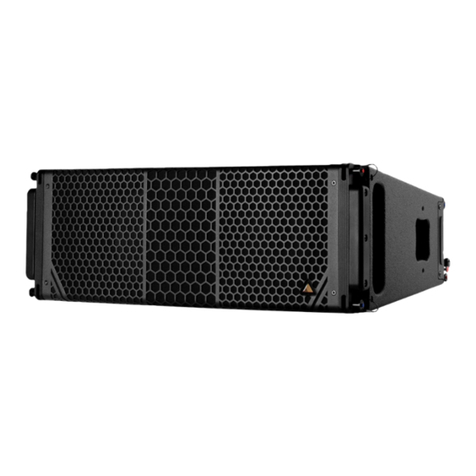
• The IS7 is an ultra compact line array enclosure designed for extended throw capabilities. It has an unobtrusive
visual design which blends seamlessly into the surrounding space. It contains two symmetrically arrayed 7”
transducers and a 3” compression driver mounted on an Adamson waveguide.
• Up to 16 IS7 can be flown in the same array when using the IS7 & IS118 Support Frame (930-0026) and up to
8 when using the S7 Micro Frame (930-0029). Due to the use of Controlled Summation Technology, the IS7
maintains a consistent nominal horizontal dispersion pattern of 100° down to 400Hz.
• The high frequency waveguide is designed to couple across the entire intended frequency band without loss of
coherence. There are 9 rigging positions available, spanning 0° to 12.5°.
• Adamson’s use of proprietary techologies such as Controlled Summation Technology and Advanced Cone
Architecture give the IS7 an extremely high maximum SPL level of 138 dB. The nominal impedance of the IS7 is
16 Ω per band, maximizing amplier efciency.
• The operational frequency range of the IS7 is 80Hz to 18kHz, +/- 3 dB.
• The IS7 is intended to be used as a standalone system or with the IS118 companion subwoofer, which brings the
usable frequency range down to 35Hz.
• The wooden enclosure is made of marine grade birch plywood, and has an aluminum rigging system mounted on
each corner. Without sacricing low resonance to composite material, the IS7 is able to maintain a low weight of
13.2 kg / 29 lbs.
• The IS7 is designed for use with Lab.gruppen’s D-Series line of installation ampliers.
Product Introduction
IS7 Ultra Compact Line Array

Page 5
Adamson Systems Engineering | IS7 User Manual
IS7 Jackplate IS7b Jackplate
IS7 & IS7b Internal Wiring (IS7b only has one input)
• The IS7 (971-0003) comes with 2x Neutrik Speakon™ NL4 connections, wired in parallel.
• The IS7b (971-0004) comes with an external barrier strip.
• Pins 1+/- are connected to the 2x ND7-LM8 MF transducers, wired in series.
• Pins 2+/- are connected to the NH3-16 HF transducer.
PARALLEL
INPUT
PARALLEL
INPUT 1+
1-
2- MF
MF
HF
2+
1+
1-
2-
2+
iS7 JACKPLATE Do Not Print This Colour
PARALLEL INPUTS
PARALLEL INPUTS
Page 5
Adamson Systems Engineering | IS7 User Manual
Wiring & Amplication
Wiring

Page 6
Adamson Systems Engineering | IS7 User Manual
The IS7 is paired with Lab.gruppen D-Series ampliers.
Maximum quantities of the IS7 per amplier model are shown below.
For a master list, please refer to the Maximum Enclosure per Amplier document,
found on the Adamson website.
Use LoadSmart™ verication to ensure that all connections are made properly. On the D-Series line of ampliers,
LoadSmart™ can be accessed through Lake Controller. Please refer to the Adamson Lake & PLM Handbook, which is
included in the Adamson Load Library, which can be found on the Adamson website.
4x IS7
D40:4L D80:4L D80:4L D120:4L
8x IS7 2x IS118, 4x IS7 12x IS7
Wiring & Amplication
Amplification
LoadSmart™

Page 7
Adamson Systems Engineering | IS7 User Manual
IS7 Lipll
Intended for use with a
single IS7
IS7 Short
Intended for use with an array
of 7 or less IS7
IS7 Array
Intended for use with an
array of 8 or more IS7
The Adamson LoadLibrary, found on the Adamson website, contains presets designed
for a variety of IS7 applications. Each preset is intended to be phase-linear with either
the IS118 or IS119 subwoofers.
Tilt overlays (found in the Array Shaping folders of the Adamson Load Library) can be used to alter the overall acoustic
response of an array. Tilt overlays apply a lter, centered at 1kHz, which reaches the noted decibel cut or boost at the
extreme ends of the listening spectrum. For example, a +1 Tilt will apply +1 decibel at 20kHz and -1 decibel at 20Hz.
Alternately, a -2 Tilt will apply -2 decibels at 20kHz and +2 decibels at 20Hz.
Please refer to the Adamson PLM & Lake Handbook for detailed instructions on recalling Tilt and Array Shaping
overlays.
Array Shaping overlays (found in the Array Shaping folders of the Adamson Load Library) are available so
comparisons can be made between the “Array” preset and the “Short” preset. When the “Array” preset is loaded, the
“Short” Array Shaping overlay can be recalled in the EQ section of Lake Controller to adjust the contour of the array to
compensate for less enclosures.
Page 7
Adamson Systems Engineering | IS7 User Manual
Presets & Control
Control
Presets

Page 8
Adamson Systems Engineering | IS7 User Manual
**12 dB crest factor pink noise at 1m, free eld, using specied processing and amplication
527 mm / 20.75 in
401 mm / 15.8 in
236 mm / 9.3 in
122 mm / 4.8 in
Frequency Range (+/- 3dB) 80 Hz - 18 kHz
Nominal Directivity (-6 dB) H x V 100° x 12.5°
Maximum Peak SPL** 138
Components LF 2x ND7-LM8 7” Neodymium Driver
Components HF Adamson NH3 3” Diaphragm / 1.4” Exit Com-
pression Driver
Nominal Impedance LF 16 Ω (2 x 8 Ω)
Nominal Impedance HF 16 Ω
Power Handling (AES / Peak) LF 500 / 2000 W
Power Handling (AES / Peak) HF 110 / 440 W
Rigging Integrated Rigging System
Connection 2x Speakon™ NL4 or Barrier Strips
Height Front (mm / in) 236 / 9.3
Height Back (mm / in) 122 / 4.8
Width (mm / in) 527 / 20.75
Depth (mm / in) 401 / 15.8
Weight (kg / lbs) 13.2 / 29
Colour Black & White (RAL 9010 as standard, other
RAL colours on demand)
Processing Lake
800 Hz 1.5 kHz 3 kHz 6 kHz 20 kHz10 kHz400 Hz200 Hz100 Hz
0°
180°
180°
90°
90°
IS7 Horizontal Pattern
Acoustic Data
Dispersion
Technical Specifications
Table of contents
Other Adamson Speakers manuals
Adamson
Adamson IS7p User manual
Adamson
Adamson S-SERIES User manual
Adamson
Adamson M15 User manual
Adamson
Adamson CS Series User manual
Adamson
Adamson S10p User manual

Adamson
Adamson CS Series User manual
Adamson
Adamson IS7c User manual

Adamson
Adamson S-SERIES User manual
Adamson
Adamson IS Series User manual
Adamson
Adamson S7 User manual
