Adamson S-SERIES User manual

Page 2
Declarations
Declarations
BUILT. STRONG.
Directive 2006/95/EC: Low Voltage Directive
973-0003 S10
973-0004 S10i
994-0002 S119
994-0004 S119i
Directive 2006/42/EC: Machinery Directive
973-0003 S10
973-0004 S10i
994-0002 S119
994-0004 S119i
930-0020 S-Series Support Frame
930-0024 S-Series Install Support Frame
930-0021 S-Series Extended Beam
931-0010 S10 Underhang
938-0019 S10 Dolly
938-0021 S119 Dolly
938-0014 Dolly Stacking Legs
E-Series | Declaration of Conformity

Page 3
Throughout this manual the potential risks are indicated by these symbols.
ATTENTION
It is compulsory to read this manual before using
the S-Series system. Supervision and competency
are the responsibility of the system owners and
operators. All intersections, joints and rigging hard
-
ware must be inspected regularly. Operators must
not assume rigging has been inspected prior to use
by someone else.
WARNING
SAFETY RISK
PAY SPECIAL ATTENTION
PINCH POINT
CAN CAUSE SEVERE
PERSONAL INJURY
TIP HAZARD
ALWAYS MOVE LOADED
DOLLY ON THE LONG EDGE
ATTENTION
IMPORTANT OPERATING
INSTRUCTIONS
E-Series | Warning & Safety Symbols
Section A
Warning & Safety Symbols
Page 4
ATTENTION
IMPORTANT OPERATING
INSTRUCTIONS
Safety Precautions
English
Espanol Deutsch
Francais
• Read these instructions, keep them available for reference, they can
be downloaded any time from https://www.adamsonsystems.com/
index.php/support Heed all warnings and follow all instructions.
• Servicing is required when the loudspeaker has been damaged in any
way, such as when the loudspeaker has been dropped; or when for
undetermined reasons the loudspeaker does not operate normally.
• Protect the cabling from being walked on or pinched.
• Use only with the rigging frames/accessories specied by Adamson,
or sold with the loudspeaker system.
• This speaker enclosure is capable of creating a strong magnetic
eld. Please use caution around the enclosure with data storage
devices such as hard drives.
• Handles are for moving the system only.
• Lea estas instrucciones y téngalas a mano cuando las necesite.
Puede descargarlas cuando desee desde https://www.
adamsonsystems.com/index.php/support Preste atención a todas
las recomendaciones y siga las instrucciones.
• Debe reparar el altavoz cuando haya algún desperfecto de cualquier
tipo, por ejemplo cuando haya caído o en ocasiones indeterminadas
en que el altavoz no funcione correctamente.
• Proteja el cableado para que no sea pisado o aplastado.
• Utilice solamente los Rigging Frames y accesorios especicados
por Adamson o que vengan con el equipo original de Adamson.
• Este recinto acústico es capaz de generar fuertes campos
magnéticos. Tenga especial cuidado al utilizar dispositivos de
almacenamiento de datos magnéticos como Discos Duros etc.
• Las agarraderas son solo para mover el sistema.
• Lesen Sie dies Anleitung und bewahren Sie sie auf. Sie kann
jederzeit unter https://www.adamsonsystems.com/index.php/
support heruntergeladen werden. Beachten Sie alle Warnungen und
folgen Sie allen Anweisungen.
• Service ist notwendig wenn der Lautsprecher in irgendeiner Art
beschädigt wurde, z.B. weil er heruntergefallen ist oder wenn er aus
anderen Gründen nicht ordnungsgemäß funktioniert.
• Schützen Sie die Lautsprecherkabel davor gequetscht oder geknickt
zu werden.
• Verwenden Sie ausschließlich das von Adamson für dieses
Lautsprechersystem spezizierte bzw. das zusammen mit dem
System erworbene Rigging-Zubehör.
• Dieser Lautsprecher kann ein starkes magnetisches Feld
erzeugen. Bitte seien Sie in der Nähe des Lautsprechers z.B. mit
Datenspeichern wie Festplatten entsprechend vorsichtig .
• Die Griffe dienen ausschließlich zum Transport des Lautsprechers
• Lire les instructions ci dessous, maintenez-les disponibles pour
référence. Ils peuvent être téléchargés à tout moment à cette
adresse. https://www.adamsonsystems.com/index.php/support
Tenez compte de tous les avertissements et suivez toutes les
instructions.
• Une maintenance s’avère nécessaire lorsqu’une enceinte a été
endommagé de quelque façon que ce soit. Que celle ci soit tombé
ou qu’elle ne fonctionne pas normalement pour des raisons
indéterminées.
• Protéger le câblage contre l’écrasement.
• Utiliser uniquement les accessoires d’accrochage fourni par
ADAMSON ou vendu avec les enceintes.
• Cette enceinte acoustique génère des champs magnétiques
intenses. Prenez les précautions nécessaires avec les appareilles de
stockage de données comme les disques durs.
• Les poignées ne doivent servir qu’à déplacer l’enceinte.
S-Series | Safety Precautions
Section A

Page 5
Table of Contents
S-Series | Table of Contents
S-Series User Manual
Introduction & Product Details
1.1 Overview 6
1.2 Predictive Software 7
1.3 S10 Spec Sheet 8
1.4 S119 Spec Sheet 9
1.7 Cardioid Subs 10
System Configuration
2.0 E-Rack Description 11
2.1 E-Rack Overview 12
2.2 Configuration Example 13
2.3 Wiring Diagrams 14
2.4 Pin Swap Cable 15
Rigging
3.0 The 4 Stack Dolly 17
3.1 Rigging Overview 18
3.2 Rigging Sticker Legend 21
3.3 Setting Angles 22
3.4 Attaching the Rigging Frame 23
3.5 Extender Beam 25
3.6 Single Point Rigging 26
3.7 Ground Stacking 27
3.8 Lowering the Array 30
3.9 Rigging the S119 31
3.10 Installation Rigging 33
Accessories
4.0 Ground Stacking Legs 35

Page 6
1.0 Introduction
1.1 Overview
This manual is designed to give the S-Series user the necessary information to accurately
fly or stack S-Series loudspeakers in all the available congurations, as well as the proper
deployment and use of S-Series loudspeakers. Safe step by step rigging procedures will be
outlined, as well as example system congurations, correct wiring and amplication and
transport.
Whether it is amplication, control, networking and monitoring, the S-Series packaging is built
to perform and endure. Our alliances have been made with companies that are leading the
industry in their technologies and in their ideologies: Dante-networking, Lake-processing and
Lab.gruppen-amplication. After all it’s the total system performance that matters.
Low-mid frequency lobing is a common side-effect of traditional 2-way enclosures.
To solve this problem, Adamson has introduced Controlled Summation Technology,
which reduces the spacing between mid frequency sources by outwardly splaying the
drivers and using overlap control between mid frequency and high frequency sources
to suppress the interference normally associated with this type of design. Doing this
also allows the high frequency sound chamber to retain its exit size, ensuring that it
retains its superior directivity control.
Adamson’s SlideLock rigging system has been designed to remove operator stress
while adding confidence. A single technician can safely and quickly fly the entire
rig, setting angles while the cabinets are sitting securely on the 4-up dolly. Once the
array is lifted, all cabinets simply align into 1 of 9 incremental splay positions.
S-Series | Introduction & Product Details
Introduction & Product Details

Page 7
1.2 Predictive Software
Introduction & Product Details
S-Series | Introduction & Product Details
Blueprint AV
Blueprint AV is a 2D & 3D modeling suite which offers a fast and intuitive work-flow, without
sacricing precision. The S-Series is included, along with all of Adamson’s other Line Array
products. Design is simple and easy, yet complex simulation options are at your nger tips.
Use basic geometric shapes to design anything from a basic eld to a complex structure.
Multi-point extrude and revolve surfaces allow for intuitive arena or stadium design.
Depending on your time constraints, Blueprint AV can be easily switched from in-depth 3D
operation to streamlined 2D operation, saving on simulation time.
Once your hang is designed, Blueprint gives you all pertinent mechanical information needed
to correctly fly the system.
Blueprint AV is now available as a native Java-run program for both PC and Mac platforms.
support.
Page 8
1.3 S10 Spec Sheet
S10 | Spec Sheets
Introduction & Product Details
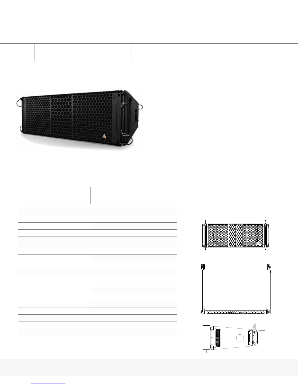
S10
The S10 is a 2-way, full range line array cabinet containing 2x ND10-LM
Kevlar Neodymium drivers (2x 16 Ω) and an NH4TA2 1.5” exit com-
pression driver (8 Ω). The critically optimized sound chamber produces
a slightly curved wavefront with a nominal dispersion pattern of 110°
x 10° (H x V). The chamber’s efciency allows for increased vertical
dispersion without sacricing high frequency presence in the far eld.
Patent-pending Controlled Summation Technology further eliminates
low-mid lobing normally associated with 2-way line source systems.
The cabinet construction uses marine grade birch plywood as well as
aircraft grade steel and aluminum, and is equipped with two Speakon™
NL8 connectors. The rigging system incorporates the best aspects of
previous advancements in our new SlideLock rigging technology.
The S10 is suited to a wide variety of applications. Its full range capa-
bility (60 Hz) at reasonable levels qualies for applications where sub
is not required. Increased vertical coverage (10°) enables the S10 to
cover theaters, arenas and stadiums with reasonable speaker quantity.
Other target applications include dance clubs, medium size festivals,
corporate events and contemporary churches.
Specications
Frequency Range (+/- 3dB) 60 Hz - 18 kHz
Nominal Directivity (-6 dB) H x V 110° x 10°
Maximum Peak SPL** 141.3 dB
Components LF 2x ND10-LM 10” Kevlar Neodymium Driver
Components HF Adamson NH4TA2 4” Diaphragm / 1.5” Exit
Compression Driver
Nominal Impedance LF 2 x 16 Ω (8 Ω)
Nominal Impedance HF 8 Ω
Power Handling (AES / Peak) LF 700 / 2800 W
Power Handling (AES / Peak) HF 160 / 640 W
Rigging SlideLock Rigging System,
Install Rigging System (S10i)
Connection 2x Speakon™ NL8
Height Front (mm / in) 265 / 10.4
Height Back (mm / in) 178 / 7
Width (mm / in) 737 / 29
Depth (mm / in) 526 / 20.7
Weight (kg / lbs) 27 / 60, 26 / 58 (S10i)
Processing Lake
737 mm / 29 in
526 mm / 20.7 in
265 mm / 10.4 in
178 mm / 7 in
**12 dB crest factor pink noise at 1m, free eld, using specied processing and amplication

Page 9
Introduction & Product Details
S119 | Spec Sheets
1.4 S119 Spec Sheet
Specications
S119
The S119 Subwoofer is the companion subwoofer to the S10. The
enclosure is loaded with a light weight, long excursion, 19” ND19 Kevlar
Neodymium driver utilizing Adamson’s Advanced Cone Architecture
and a 5” voice coil for exceptional power handling. It is mounted in an
ultra-efcient front-loaded enclosure, designed to reproduce clean,
musical low frequency information.
The cabinet construction uses marine grade birch plywood as well as
aircraft grade steel and aluminum, and is equipped with Speakon™ NL8
connectors. The integrated rigging system matches the rigging for the
S10 and can be flown or stacked in the same array without the need for
an adapter frame.
742 mm / 29.2 in
630 mm / 24.8 in 543.5 mm / 21.4 in
**12 dB crest factor pink noise at 1m, half space, using specied processing and amplication
Frequency Range (+/- 3dB) 30 Hz - 80 Hz
Maximum Peak SPL** 138 dB
Components LF ND19 19” Kevlar Neodymium Driver
Nominal Impedance LF 8 Ω
Power Handling (AES / Peak) LF 1200 / 4800 W
Rigging Integrated Rigging System,
Install Rigging System (S119i)
Connection 5x Speakon™ NL8: 2x Front (Pins 2 +/-), 2x Rear Par-
allel (Pins 1 +/-) and 1x Rear Output (Pin 2 to 1)
Height Front (mm / in) 543.5 / 21.4
Width (mm / in) 742 / 29.2
Depth (mm / in) 630 / 24.8
Weight (kg / lbs) 46 / 102, 45.4 / 100 (S119i)
Supported Processing Lake
Page 10
1.7 Cardioid Subs
Introduction & Product Details
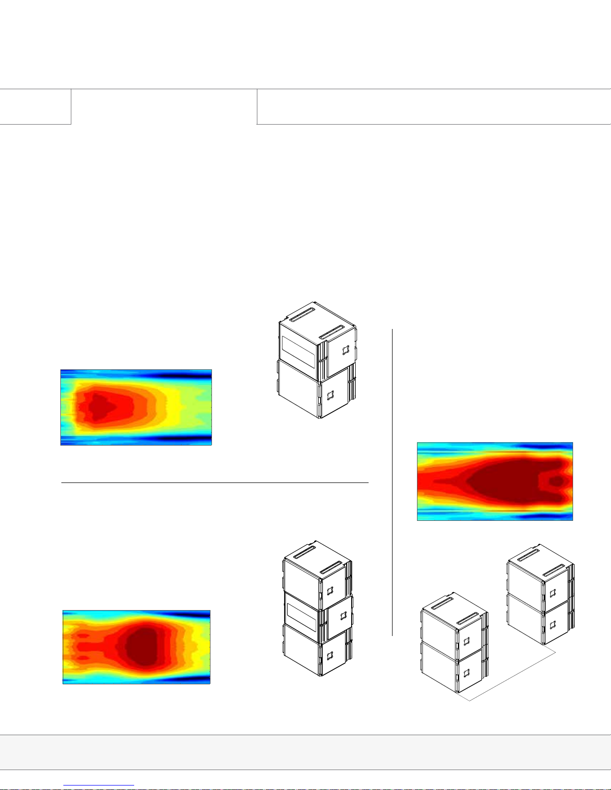
Every Adamson subwoofer has specifically designed cardioid presets. Adamson utilizes three
configurations ranging from a minimal footprint and minimized rear rejection to larger setups
that eliminate virtually all audio energy behind the array. Please refer to the Lake Preset Loading
Manual for further instructions.
Front-Back-Front
The FBF preset exhibits higher output from
the front of the array. A similar footprint
to the FB configuration, this stack is 3
enclosures high.
24
22
20
18
16
14
12
10
8
6
4
2
0
-2
-4
-6
-8
-10
100
180
120
60
0
-60
-120
-180
Part1.txt - Copy2
(deg) Axial angle
Sound pressure, Level (dB)
Frequency (Hz)
20 30 40 50 60 70 80 90
150
90
30
-30
-90
-150
Front-Back
The FB preset should be used in situations
where a minimal footprint is desired.
Only 2 enclosures stacked ensures that
sightlines will not be impaired.
24
22
20
18
16
14
12
10
8
6
4
2
0
-2
-4
-6
-8
-10
100
180
120
60
0
-60
-120
-180
Part1.txt - Copy
(deg) Axial angle
Sound pressure, Level (dB)
Frequency (Hz)
20 30 40 50 60 70 80 90
150
90
30
-30
-90
-150
End-Fire 66
The EF66 preset should be used
in situations where the most
rear cancellation is desired.
Unlike traditional end-fire
arrays, Adamson’s proprietary
preset eliminates a wide range
of frequencies in the rear of the
array.
24
22
20
18
16
14
12
10
8
6
4
2
0
-2
-4
-6
-8
-10
100
180
120
60
0
-60
-120
-180
S119 EF
(deg)
Soundpressure, Level (dB)
Frequency (Hz)
20 30 40 50 60 70 80 90
150
90
30
-30
-90
-150
66”
S-Series | Cardioid Subs
Page 11
2.0 E-Rack Description
System Conguration
S-Series | System Conguration
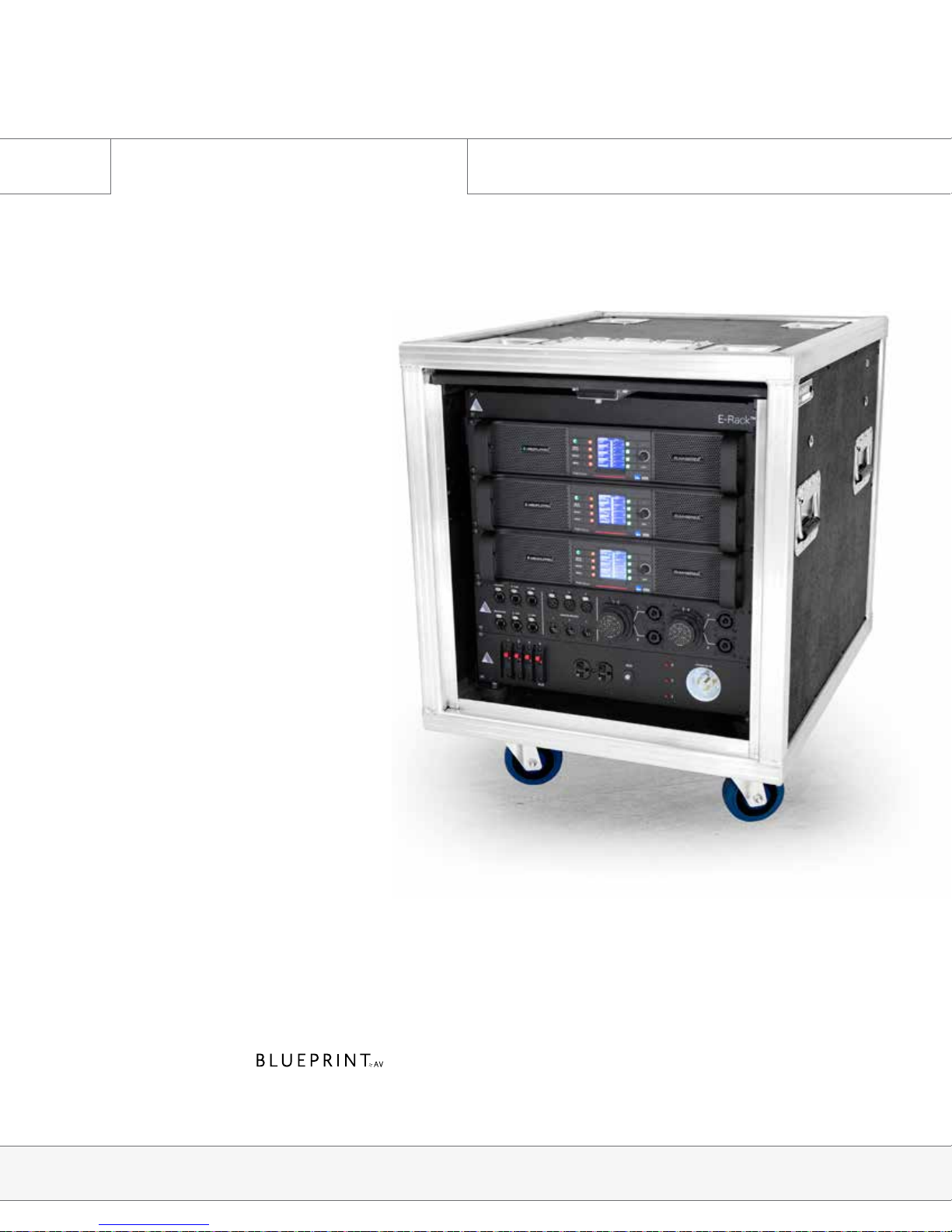
Adamson has developed a unified
rack solution, configured to
interface seamlessly with our line of
loudspeaker products. All E-Racks
are equipped with two or three Lab.
gruppen PLM+ series amplifiers,
featuring Lake processing and Dante
audio networking functionality. The
Adamson Audio Panel provides
Analog and AES inputs, Speakon NL8
and Socapex outputs, and etherCON
RJ45 connections, designed for dual
redundant Dante setups. A managed
Gigabit Ethernet switch and an AC
distribution panel available in 120
V or 230 V versions complete the
hardware. The entire package fits into
a compact and lightweight 10U rack,
designed with interior suspension,
hinged doors and extra rails for
secure & efficient use of space.
Adamson Touring Rack
E-Rack elements are comprised of:
• 10U suspended rack with hinged, sliding front and rear doors
• Up to three Lab.gruppen PLM 12K44 ampliers (8 and 12-Channel versions available)
• Adamson Audio Panel
• Adamson AC Panel, 120 V or 230 V (region specic)
• Cisco SG300-20 managed switch
• Includes one Personal License per rack

Page 12
2.1 E-Rack Overview
System Conguration
S-Series | System Conguration
PUSHPUSHPUSH
PUSHPUSHPUSH
Adamson has developed a unied rack solution congured to interface seamlessly with our
line of Loudspeaker products. For more information on the E-Rack, please refer to the E-Rack
brochure available on the Adamson Systems website.
2 or 3x Lab.gruppen PLM 12K44
1x Adamson Audio Panel, incl. Analog and
AES in and thru-puts (XLR), Speaker out-
puts (NL8 and Socapex), Gigabit Network
Ports (Ethercon RJ45)
1x AC Distribution Panel, L21-30 input or
CEE 32A 3-Phase 400V/230V 3L+N+PE
(Red CEE connector), depending on region
1x DANTE Certied Switch (Rear Side)
Page 13
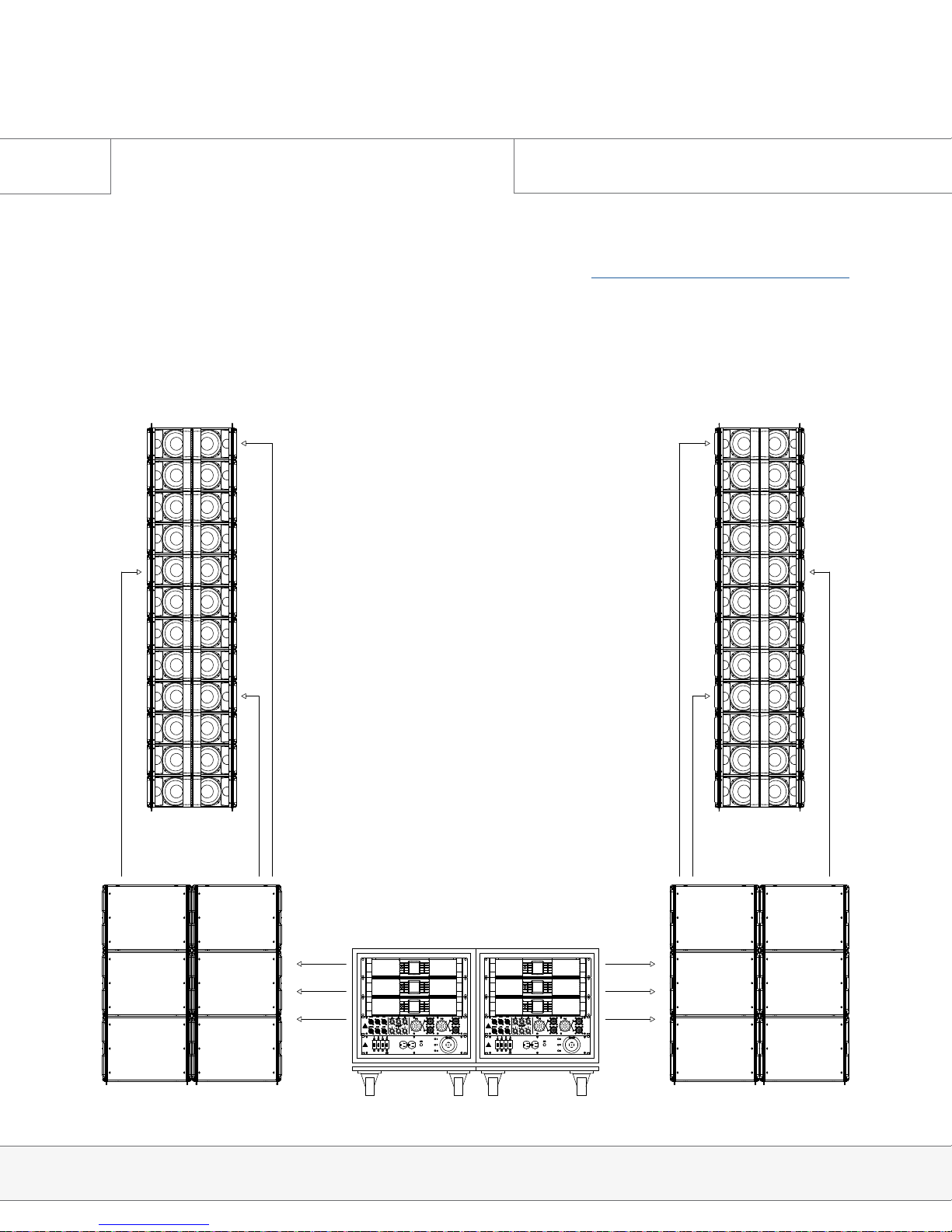
2.2 Configuration Example
System Conguration
S-Series | System Conguration
This example conguration demonstrates the efciency of the system. For further information re-
garding congurations, please refer to the Adamson Document S-Series Conguration Brochure.
PUSHPUSHPUSH
PUSHPUSHPUSH
PUSHPUSHPUSH
PUSHPUSHPUSH
Page 14
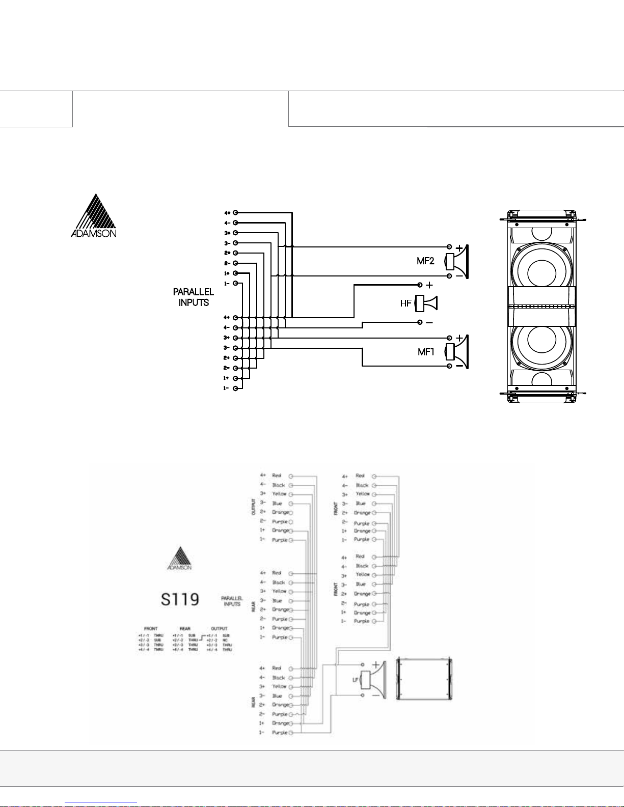
2.3 Wiring Diagrams
System Conguration
PARALLEL
INPUTS
MF2
MF1
HF
HF+4 -4RED BLACK
MF+3 -3YELLOW BLUE
THRU+2 -2ORANGE PURPLE
+1 THRU -1ORANGE PURPLE
S10
S-Series | Wiring Diagrams
S10
2-way line source enclosure [973-0003]
LMF - 2x 10” ND10-LM[940-0025], HF - 1x 4”NH4TA2 [140-0020]
SlideLock™ rigging system
S119
Subwoofer [994-0002]
LF - 1x 19” ND19, SlideLock™ rigging system

Page 15
2.4 Pin Swap Cable
System Conguration
A single PLM + amplier can drive up to 8x S10 enclosures, so long as the NL803 Pin Swap Cable
(920-0024) is utilized. This cable is marked with red heat shrink to distinguish it from other NL8
links in a user’s inventory.
Pins 1 & 2 are switched with pins 3 & 4 in this cable, allowing S10 users to load all output channels
of a Lab.gruppen PLM + amplier. Here is an example of how to congure the outputs in Lake
Controller to make use of this cable:
Since the PLM + ampliers offer four
DSP modules, recalling 2x LF and 2x
HF modules will allow for greater zone
control in an S10 array.
Page 16
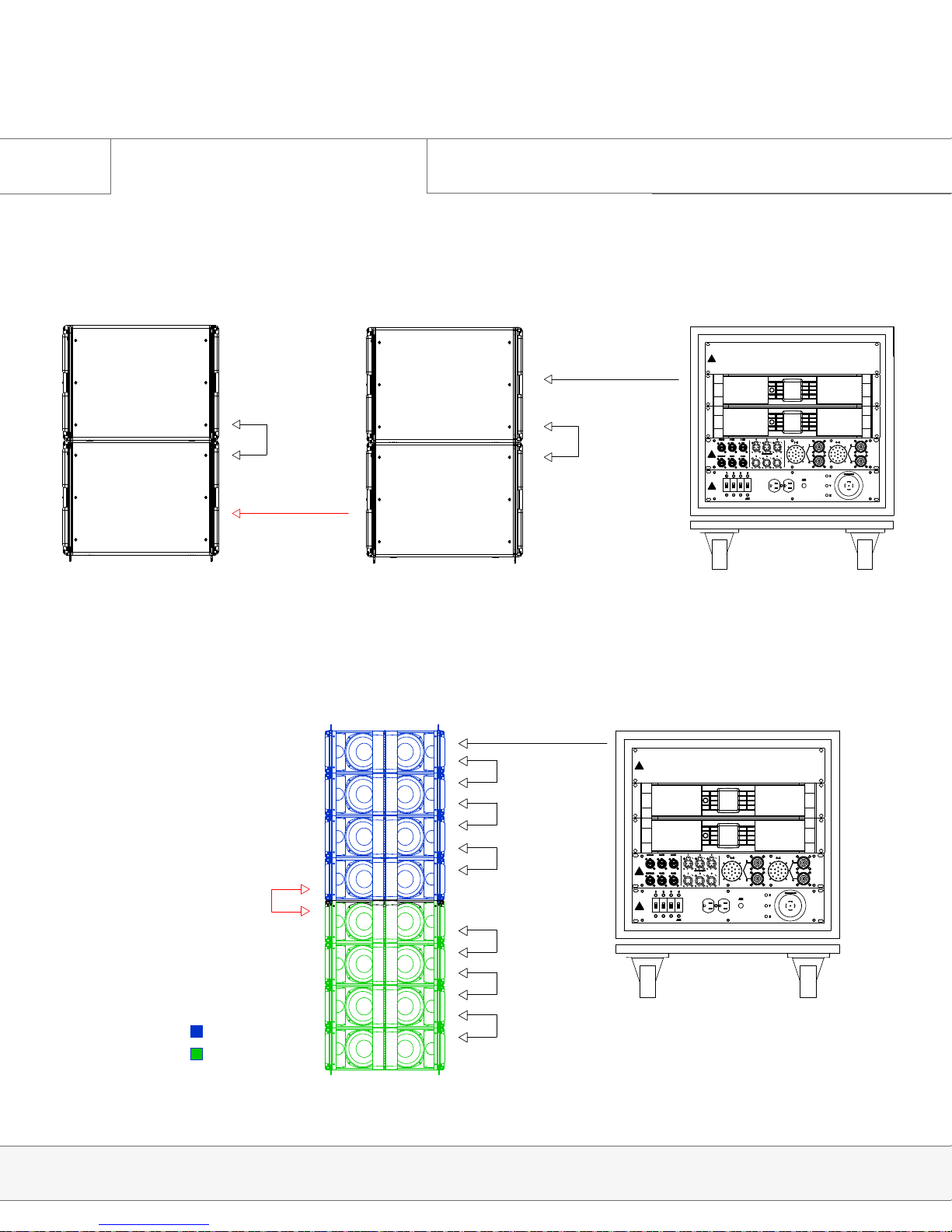
2.4 Pin Swap Cable
System Conguration
E-Rack to Parallel
Parallel to Parallel
(Pin Swap Cable)
Output to
Parallel
Output to
Parallel
PUSHPUSHPUSH
PUSHPUSHPUSH
Pin Swap Cable
Between Box 4 and 5
= Circuits 3 & 4
= Circuits 1 & 2
PUSHPUSHPUSH
PUSHPUSHPUSH
Below is a description of how to cable subwoofers when using all four channels of the PLM + am-
plier as subwoofer channels.
When cabling the S10s in groups of 8, it is vital to use the pin swap cable between boxes 4 and 5.
Any instance where the S10 is using all four channels of amplication requires the use of the pin
swap cable.

Page 17
3.0 The 4 Stack Dolly
Rigging
S-Series | Rigging
TIP HAZARD
ALWAYS MOVE LOADED
DOLLY ON THE LONG EDGE
Transporting the 4 Stack Dolly
There is a tip hazard when transporting a 4 stack on uneven ground or on a ramp. To avoid tipping the dolly,
It should always travel with sides of the cabinet to the front or back.
*On the 4 stack dolly, the bottom cabinet is held in place by the rear, blue push-pin..

Page 18
3.1 Rigging Overview
Rigging
S-Series | Rigging
ATTENTION
IMPORTANT OPERATING
INSTRUCTIONS
The SlideLock Rigging System
The SlideLock Rigging System allows for the operator to set enclosure angles while still stacked on the dolly. A
series of push pins maintain angular position and lock in connecting rigging pieces. Caution should be taken while
connecting cabinets to ensure hands are out of the way.
The order of operation of the rigging system is: prep angles, remove connection pins, guide into place and secure
connecting pins.
Fig. 1
Fig. 2
0 0°
1 1°
2 2°
3 3°
4 4°
5 5°
6 6°
7 6.9°
8 10°
Storage in enclosure
There are 9 angles, 0 to 8, and an
additional ‘Storage’ being the ‘idle’
or ‘rest’ position, when the rigging
hardware is all the way down and
the boxes aren’t connected. It is
applicable when the enclosure is
not in use, to protect the rigging
hardware from damage. To keep the
system intact for transport, leave the
angles pinned in.
The angles are numbered as well
as color coded to mark which slot
should be pinned with the attached
push-pin. (Fig. 2) The following
rigging positions are equal to the
following degrees for the S10 (Fig. 1)

Page 19
3.1 Rigging Overview
Rigging
S-Series | Rigging
ATTENTION
IMPORTANT OPERATING
INSTRUCTIONS
The S-Series Support Frame is designed for use with all S-Series enclosures. It consists of a
steel frame and can be paired with the S-Series Extender Beam. Always refer to Blueprint AV™
for correct rigging instructions.
In standalone mode, the frame can be used to lift flat to slightly-
angled arrays. Two rigging plates are provided for dual motor
operation, and if two motors are not available, one lifting plate
may be repositioned towards the center of the frame. Please
refer to Blueprint AV™ when determining proper lifting plate
location.
In order to attach the S-Series Extender Beam, the lifting plates
must be removed and replaced with Extended Beam plates.

Page 20
3.1 Rigging Overview
For arrays with little to no incline,
the S-Series Extender Beam
centered will usually provide the
best weight dispersion.
For arrays with negative incline,
the S-Series Extender Beam
positioned towards the back of
the frame will provide the best
weight dispersion.
For arrays with positive incline,
the S-Series Extender Beam
positioned towards the front of
the frame will provide the best
weight dispersion.
Rigging
S-Series | Rigging
ATTENTION
IMPORTANT OPERATING
INSTRUCTIONS
Other manuals for S-SERIES
2
Table of contents
Other Adamson Speakers manuals

Adamson
Adamson IS7c User manual

Adamson
Adamson Point Series User manual

Adamson
Adamson S-SERIES User manual

Adamson
Adamson IS7 User manual

Adamson
Adamson IS Series User manual

Adamson
Adamson CS Series User manual

Adamson
Adamson M15 User manual

Adamson
Adamson IS7p User manual

Adamson
Adamson CS Series User manual

Adamson
Adamson CS Series User manual


Popular Speakers manuals by other brands

Velodyne
Velodyne DD-18+ Specifications

Monster
Monster Precision Micro Bluetooth 100 User guide and warranty information

Nady Audio
Nady Audio P-Cab PCS-8 Features, instructions & technical data

Toa
Toa CS-304U instruction manual

Sony
Sony SRS-XB402G operating instructions

Montarbo
Montarbo W24As Connection examples


