Adastra 952.916 User manual

Ref. No. 952.916
CD/FM TUNER MIXER AMP
Operation Manual
CH-4 AUXCH-3CH-2
INPUT VOLUME
FM DIGITAL TUNER
952.916 CD-TUNER-AMPLIFIER
CD AUDIO PLAYER
TONE CONTROL
CH-1
0 10 0 10 0 10 0 10 0 10 -10 +10 -10 +10
BASS TREBLE MASTER POWER
0 10
+3
0dB
-3
-6
-9
ON
RANDOM
REPEAT
PLAY
ALL
0
0
PROGRAM REPEAT DOWN UP
AUX
CD TUNER
TUNE
BAND
1 2 3
4 5 6
OPEN/CLOSEPLAY/PAUSESTOP
AMPLIFIERS FOR PUBLIC ADDRESS
CD/FM TUNER MIXER AMP

2
IMPORTANT
Then wires in the mains lead are coloured in accordance with the
following code:
Green & Yellow: Earth (E)
Blue: Neutral (N)
Brown: Live (L)
As the colours of the wires in the mains lead of this apparatus may
not correspond with the coloured markings identifying the terminals
in your plug proceed as follows:
The wire which is coloured green and yellow must be connected to
the terminal which is marked by the letter E or by the safety earth
symbol or coloured green and yellow. The wire which is coloured
blue must be connected to the terminal which is marked with the
letter N or coloured black. The wire which is coloured brown must
be connected to the terminal which is marked with the letter L or
coloured Red. If a 13Amp (BS1363) plug or any other type of plug
is used, a 5 Amp fuse must be fitted either in the plug or at the
distribution board.
GENERAL INSTALLATION
DO NOT run microphone cables near mains, data,telephone or 100V
line cables
DO NOT run 100V line cables near data, telephone or other low
voltage cables
DO NOT exceed 90% of the amplifiers output power when using
100V line (speech only)
DO NOT exceed 70% of the amplifiers output power when using
100V line (high level background music)
DO NOT use re-entrant horn loudspeakers for background music
unless the loudspeaker has been specifically designed for this
purpose.
AVOID Jointing the microphone cable, when this is unavoidable make
sure a good screened connector is used, e.g. XLR
ALWAYS use a balanced or floating low impedance microphone
terminating into a balanced input on long microphone cable runs.
ENSURE that all loudspeakers are in-phase
ENSURE that there are no short circuits on the loudspeaker line
before connection to the amplifier.
WARNING:
THIS APPLIANCE MUST BE EARTHED
OPERATION MANUAL - ADASTRA 952.916 GB
WARNING: SHOCK HAZARD - DO NOT OPEN
AVIS: RISQUE DE CHOC ELECTRIQUE - NE PAS OUVRIR
CAUTION
RISK OF ELECTRIC SHOCK
DO NOT OPEN
120W OUTPUT POWER
This model can deliver very high output power at less than 1% THD
VERSATILE AND EASY TO USE
Incorporating all the necessary system components to provide versatility in an easy to
use form: five channels of input signals (MIC/ LINE 1-4, AUX input).
PRIORITY AND MUTING
Input to INPUT 1 will activate the priority circuit, which temporarily mutes signals
from other inputs, tuner or tape. Input also activates muting.
TONE CONTROL
BASS / HIGH: The two-band tone control provides +/-10dB of control over the TREBLE
and BASS range.
DIGITAL TUNER
Ability to store up to eighteen broadcasting frequencies in the system’s memory, in a
simple and easy to use manner.
EMERGENCY POWER SUPPLY
Two terminals on the rear of the panel for 24VDC emergency power supply.
FEATURES

3
FRONT PANEL CONTROLS (Fig. 1)
1. POWER SWITCH
Pressing this switch to ON will make the
power indicating LED ON and supply the
power to this unit.
2. MASTER VOLUME
This control is used for adjusting the volume
of finally mixed sound.
3. TONE CONTROL
The “Bass” and “Treble” tone controls provide
+/- 1OdB of control on the range of TREBLE
and BASS.
These frequencies are: TREBLE: 1OkHz and
BASS: 100Hz
4. AUX VOLUME
This control is used to regulate the volume of
the CD, AUX and tuner inputs.
5. CD, AUX AND TUNER BUTTONS
These buttons are used to select the signal
source (CD, TUNER and AUX) on the AUX
channel.
6. INPUT 1 - INPUT 4 INPUT VOLUME
These volume controls regulate the INPUT 1
- INPUT4 level.
7. OUTPUT LEVEL
The output level is displayed on the LED
bargraph.
CH-4 AUXCH-3CH-2
INPUT VOLUME
FM DIGITAL TUNER
952.916 CD-TUNER-AMPLIFIER
CD AUDIO PLAYER
TONE CONTROL
CH-1
0 10 0 10 0 10 0 10 0 10 -10 +10 -10 +10
BASS TREBLE MASTER POWER
0 10
+3
0dB
-3
-6
-9
ON
RANDOM
REPEAT
PLAY
ALL
0
0
PROGRAM REPEAT DOWN UP
AUX
CD TUNER
TUNE
BAND
1 2 3
4 5 6
OPEN/CLOSEPLAY/PAUSESTOP
(6) (4) (3) (2) (7) (1)
(5)
CH-4 AUXCH-3CH-2
INPUT VOLUME
FM DIGITAL TUNER
952.916 CD-TUNER-AMPLIFIER
CD AUDIO PLAYER
TONE CONTROL
CH-1
0 10 0 10 0 10 0 10 0 10 -10 +10 -10 +10
BASS TREBLE MASTER POWER
0 10
+3
0dB
-3
-6
-9
ON
RANDOM
REPEAT
PLAY
ALL
0
0
PROGRAM REPEAT DOWN UP
AUX
CD TUNER
TUNE
BAND
1 2 3
4 5 6
OPEN/CLOSEPLAY/PAUSESTOP
CD Section (Fig. 2)
1. CD LOADING TRAY
CD loading tray.
2. “OPEN/CLOSE” BUTTON
This button is used to open / close
the CD loading tray.
3. “PLAY/PAUSE” BUTTON
This button starts CD playing. This function is
indicated by the green “PLAY” indicator light
in the “FUNCTION” area (9). By pressing the
button, again, the unit will pause.
The “PLAY” indicator displays this function
by flashing.
To return to play mode, press the button
again.
4. “STOP” BUTTON
This button is used to stop the CD.
5. “TRACK UP/DOWN” BUTTONS
The purpose of these controls is to play a
specific track on the CD. The number of the
CD track is shown on the “PROGRAM” (10)
display unit.
6. “REPEAT” BUTTON
This button is used to repeat each single track
or the entire CD.
By pressing the button just once, the selected
track is repeated. This function is indicated
CH-4 AUXCH-3CH-2
INPUT VOLUME
FM DIGITAL TUNER
952.916 CD-TUNER-AMPLIFIER
CD AUDIO PLAYER
TONE CONTROL
CH-1
0 10 0 10 0 10 0 10 0 10 -10 +10 -10 +10
BASS TREBLE MASTER POWER
0 10
+3
0dB
-3
-6
-9
ON
RANDOM
REPEAT
PLAY
ALL
0
0
PROGRAM REPEAT DOWN UP
AUX
CD TUNER
TUNE
BAND
1 2 3
4 5 6
OPEN/CLOSEPLAY/PAUSESTOP
(9) (10) (7) (6) (5)
(1) (4) (3) (2) (8)

by the green “REPEAT” indicator in the
“FUNCTION” area (9).
By pressing the button twice, the complete
CD will be repeated. This function is indicated
by the simultaneous lighting up of the
“REPEAT” and “REPEAT ALL” indicator lights
in the “FUNCTION” area.
To disengage this function, press the button
until both indicator lights go off.
7. “PROGRAM” BUTTON
This button is used to programme a sequence
of tracks contained on a CD.
To perform the sequence to be listened to,
the CD must be stopped.
The total number of tracks in the CD appears
on the “PROGRAM” area display. By pressing
the button, the display will start to flash and,
by means of the “TRACK UP/DOWN” controls,
the desired track will be selected.
If the “PROGRAM” key is pressed again, the
desired track will be stored in the sequence
to be repeated. Perform this operation for the
desired tracks.
Once the choice has been made, press the
“PLAY/PAUSE” key to begin listening.
This function is indicated by flashing of
the “PROGRAM” indicator light in the
“FUNCTION” area. This indication will remain
engaged throughout programming.
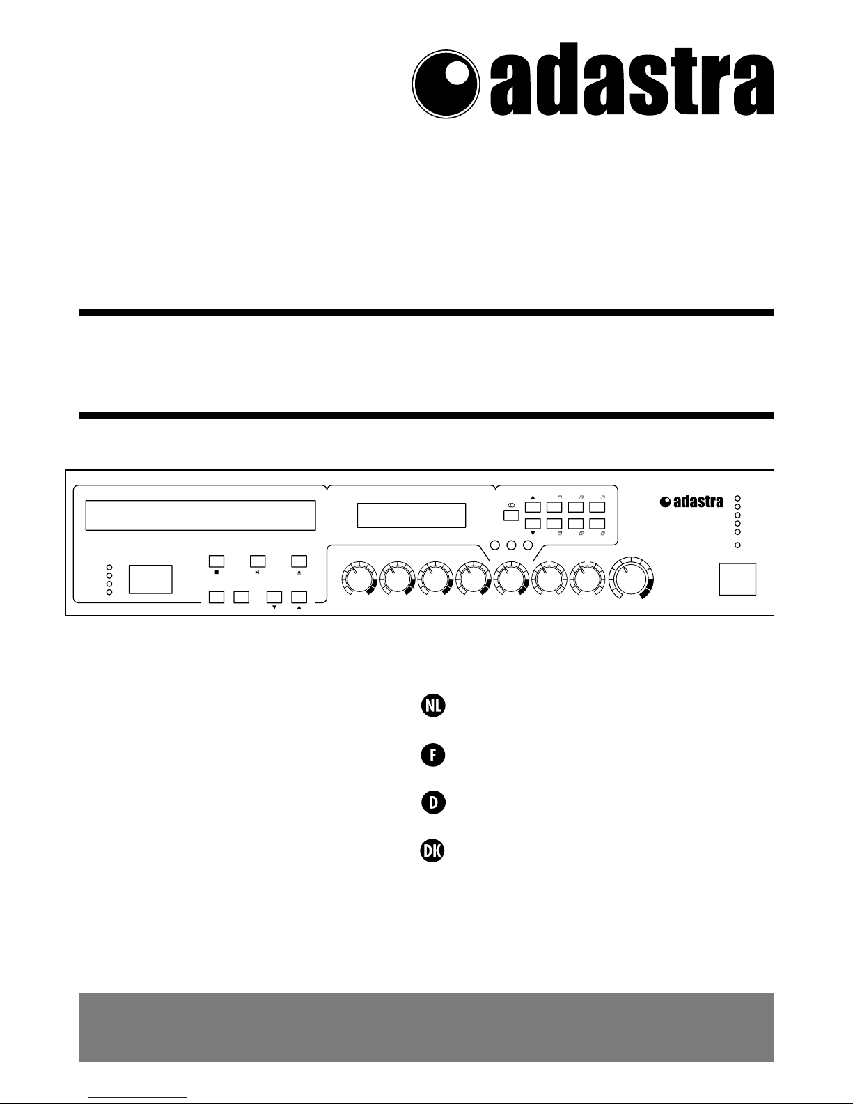
8. DISPLAY MODE
This display unit shows the state of the source
on the AUX channel (CD, TUNER, AUX).
9. STATUS LED INDICATORS
These LEDs indicate the status of the CD. Their
meanings have been explained previously
according to function.
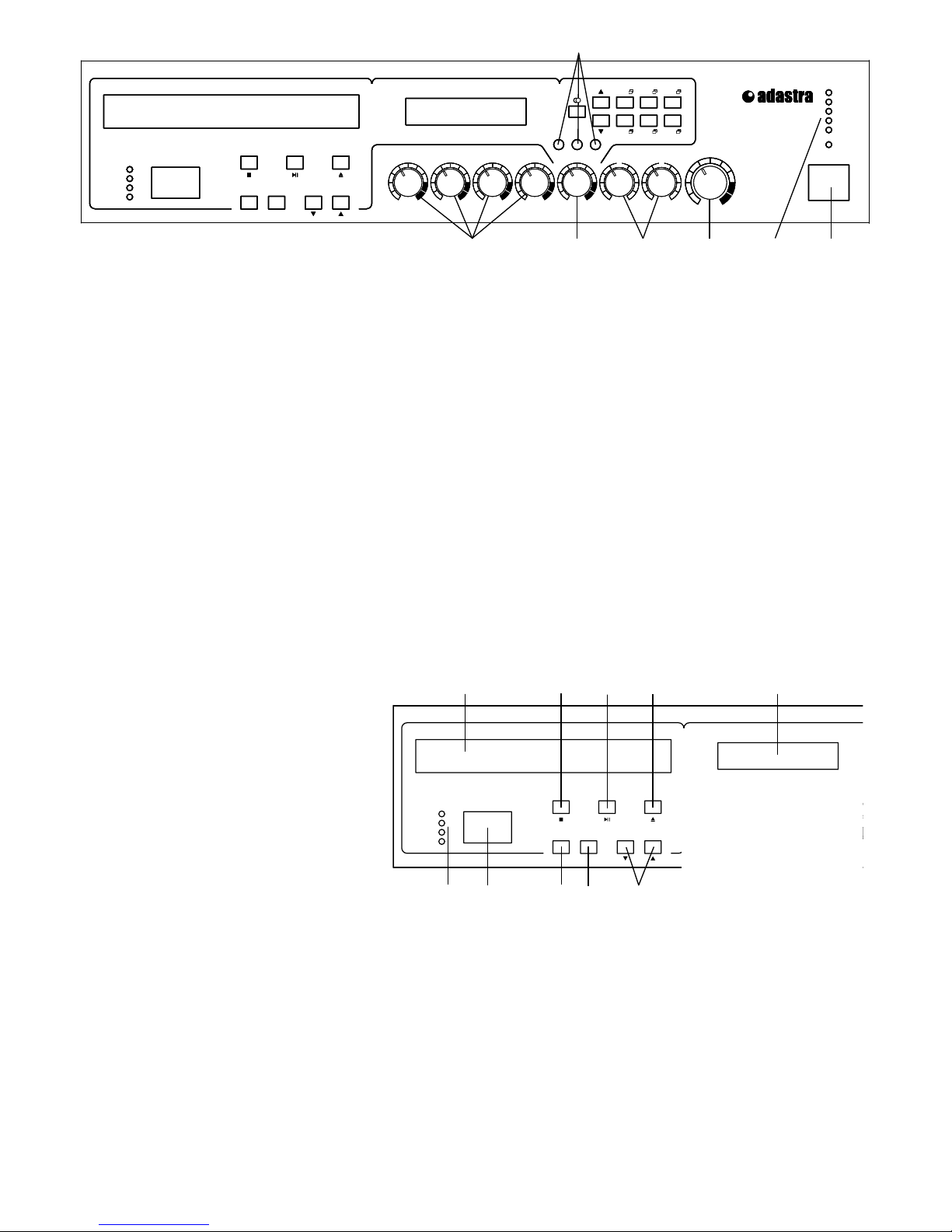
10. CD TRACK DISPLAY UNIT
This display unit indicates the number of the
track being listened to.
4
Tuner section (Fig. 3)
1. TUNER FREQUENCY DISPLAY
By means of this display, it is possible to
display the band and frequency of the tuner
and stored channel.
2. BAND SELECTION BUTTON
This button is used to select the FM1, FM2
or FM3 band.
3.
STORE/PRESET STATION RECALL BUTTONS
(MEMO 1 - 6)
The purpose of these buttons is to recall the
six frequencies stored in the three different
bands. Altogether, a total of eighteen
transmission frequencies can be stored. The
same button is used to store the desired
transmission frequency. The procedure as
follows:
1. Select the band by means of BAND button
(2);
2. Select the frequency to be stored by means
of TUNE UP/TUNE DOWN button (4);
3. Press the store button (3) in which the
desired frequency is to be stored for at least
2-3 seconds
4. The present status of the tuner will be
memorised in the selected address.
When the button is pressed for over 3
seconds, a search is made for the next
strongest frequency.
4. UP/DOWN BUTTON
When the button is momentarily pressed
once, the FM frequency will adjust with a
single UP/DOWN count.
When the button is pressed for over 3
seconds, a search is made for the next
strongest frequency.
CH-4 AUXCH-3CH-2
INPUT VOLUME
FM DIGITAL TUNER
952.916 CD-TUNER-AMPLIFIER
CD AUDIO PLAYER
TONE CONTROL
CH-1
0 10 0 10 0 10 0 10 0 10 -10 +10 -10 +10
BASS TREBLE MASTER POWER
0 10
+3
0dB
-3
-6
-9
ON
RANDOM
REPEAT
PLAY
ALL
0
0
PROGRAM REPEAT DOWN UP
AUX
CD TUNER
TUNE
BAND
1 2 3
4 5 6
OPEN/CLOSEPLAY/PAUSESTOP
(1) (2) (4) (3)

5
REAR PANEL CONTROLS (Fig. 4)
1. FUSE HOLDER
Main fuse housing.
If blown, replace it with same type fuse as
specified below. If the fuse continuously
blows, refer servicing to qualified personnel.
VOLTAGE = AC 230V
FUSE = T1, 6A/250V
2. MAINS INPUT SOCKET
For connecting the power cable supplied with
the product.
3. POWER VOLTAGE CHANGE
Permits changing the power supply voltage
(230/115V).
This switch is preset; in case of variation,
make sure the FUSE is correct (1).
4. ANTENNA TERMINAL
The purpose of this terminal is to connect the
antenna cable when the tuner is used
5. “AUX IN” AUX INPUT CONNECTOR
An auxiliary source can be connected to this
input (cassette player, CD....).
6. LINE OUTPUT CONNECTOR
The line output signal of this unit can be used
to connect up another amplifier, e.g., a
recorder or a signal processor, etc
7. INPUTS 1-4, MIC/LINE
These are XLR microphone/ line input
connectors with balanced electrical circuit.
8. INPUT GAIN SELECT
According to the input signal source, the gain
switches to MIC/LINE.
MIC (Microphone) -54dB (2mV)
LINE (Deck, etc.) -1 2 d B (250mV)
10kΩ
9. PHANTOM POWER SWITCH
This switch turns on the phantom power
supply for all channels. Use this switch when
you are using condenser microphones.
When this switch is turned on, DC +18V will
be supplied to pins 2 and 3 of each INPUT
socket. If you do not need phantom power,
be sure to leave this turned off.
10. VOX SWITCH (priority)
This switch can be used to switch the VOX
control (AUX priority) on and off. This
control affects all four inputs 1- 4 and AUX
11. FM FREQUENCY SELECTION SWITCH
This switch permits selecting the tuning
frequencies according to European (FM 87.5-
108 MHz) or US standard (FM 87.5-107.9
MHz)
12. SPEAKER OUTPUT TERMINALS
Use speakers with the same or higher than
the nominal output impedance of the
amplifier.
4Q 8Q 70V 100V
22V 31V 40,8Ω 83,3Ω
13. 24Vdc EMERGENCY POWER SUPPLY
These terminals permit connection of a 24Vdc
emergency power supply.
(3) (4) (11) (7) (10)
(1)

6
ANTENNA APPLICATION
FM RECEIVING ANTENNA
FM broadcasting weakens in hills and valleys,
around buildings and in iron-reinforced
buildings.
ANTENNA INSTALLATION EXCLUSIVELY FOR FM
Listening to the broadcasting, fix the antenna
after deciding the location and the direction
so that the reception may be optimised.
ANTENNA INSTALLATION USING COAXIAL CABLE
Noisy reception may occur in built-up areas
and factory sites as around power cables. This
may be the case even when an antenna is
used exclusively for FM. In these regions,
install the antenna using 75Ω coaxial cable.
INDOOR ANTENNA
In the regions where FM broadcasting is
heard comparatively well due to the near
distance to the station or wooden structure,
you can receive broadcasting of good quality
by using T-type antenna. (Using matching
trans:300/75Ω)
SPECIFICATIONS
AMPLIFIER SECTION
Rated Output . . . . . . . . . . . . . . . . . . 120W (RMS)
Frequency Responce. . . . . . . . . 50Hz to 15000Hz
Signal to Noise Ratio
Mic 1-4. . . . . . . . . . . . . . . . . . . . . . . . . . .60dB
Aux . . . . . . . . . . . . . . . . . . . . . . . . . . . . . .80dB
Total Harmonic Distortion
(at 1kHz Rated Output)
. . . . . . . Less than 1.0%
Tone Controls Master volume
Bass. . . . . . . . . . . . . . . . . . .+/-10dB at 100Hz
Treble . . . . . . . . . . . . . . . . .+/-10dB at 10kHz
Input Sensitivity/lmpedance
Mic1-4 . . . . . . . . . . . . . Balanced 2mV/600Ω
Line Input 1-4 . . . . .Balanced 250m V/10kΩ
Aux . . . . . . . . . . . . . . . . . . . . . . .250mV/10kΩ
Speaker Output/Impedance. . . . . .120W 4Ω/22V
8Ω/31V
70V/40,8Ωs
100V/83,3Ω
TUNER SECTION
Radio range
European standard FM . . . 87.5MHz-108MHz
US standard FM . . . . . . . . 87.5MHz-107.9MHz
Antenna Input. . . . 300Ω Twin Lead or75Ω Coax
Signal to Noise Ratio . . . . . . . . . . . . . . . . . . .60dB
CD SECTION
THD (1kHz). . . . . . . . . . . . . . . . . . . Lesst han 0.2%
Signal to noise ratio. . . . . . . . . . more than 85dB
Frequency response -3dB . . . . . . . . 20Hz-20kHz
PROTECTION
Amplifier:. . . . . . . . . . . . . . . . . . . . . . . . . . . . . . . . .
Short-Circuit, Current Limiter, Thermal Cut-Out
Load: . . . . . . . . . . . . . . . DC Offset, Turn-On/Turn
Off Transients (Delay), Output Fuse
Mainframe: . . . . . . . . . . . . . . . . . . . . AC Line Fuse
GENERAL
PowerSource . . . . . . . . . . . . . . . . . . 230Vac, 50Hz
PowerConsumption . . . . . . . . . . . . . . . . . . . 350W
Dimensions (WxDxH) . . . . . . 430 x 340 x100mm
Weight (Net) . . . . . . . . . . . . . . . . . . . . . . . . 11.9kg
NOTE: Specifications and design are subject to change without notice.

7

8

9
Other manuals for 952.916
1
Table of contents
Other Adastra Amplifier manuals

Adastra
Adastra IWA Series User manual

Adastra
Adastra A Series User manual

Adastra
Adastra RMS605 User manual

Adastra
Adastra PA5120RD User manual

Adastra
Adastra A120TUD User manual

Adastra
Adastra 952.996 User manual

Adastra
Adastra SA180 User manual

Adastra
Adastra RS605 User manual

Adastra
Adastra 953.113UK User manual

Adastra
Adastra LA-75 User manual

Adastra
Adastra A22 User manual

Adastra
Adastra IW30B User manual

Adastra
Adastra 953.122UK User manual

Adastra
Adastra A200 User manual

Adastra
Adastra US Series User manual

Adastra
Adastra A126 User manual

Adastra
Adastra A121U User manual

Adastra
Adastra 952.916 User manual

Adastra
Adastra RM1202 User manual

Adastra
Adastra UM60 User manual