ADCMT 6241A User manual

MANUAL NUMBER
C
Printed in Japan
ADC CORPORATION
All rights reserved.
6241A/6242
DC Voltage Current Source/Monitor
Operation Manual
FOE-00000029B00
First printing June1, 2008
Applicable Models
6241A
6242
2008
Cover


Safety-1
Safety Summary
FOE-ANZENA00
To ensure thorough understanding of all functions and to ensure efficient use of this instrument, please read the
manual carefully before using. Note that ADC Corporation (hereafter referred to as ADC) bears absolutely no re-
sponsibility for the result of operations caused due to incorrect or inappropriate use of this instrument.
If the equipment is used in a manner not specified by ADC, the protection provided by the equipment may be im-
paired.
• Warning Labels
Warning labels are applied to ADC products in locations where specific dangers exist. Pay care-
ful attention to these labels during handling. Do not remove or tear these labels. If you have any
questions regarding warning labels, please ask your nearest ADC dealer. Our address and phone
number are listed at the end of this manual.
Symbols of those warning labels are shown below together with their meaning.
DANGER: Indicates an imminently hazardous situation which will result in death or serious
personal injury.
WARNING: Indicates a potentially hazardous situation which will result in death or serious
personal injury.
CAUTION: Indicates a potentially hazardous situation which will result in personal injury or
a damage to property including the product.
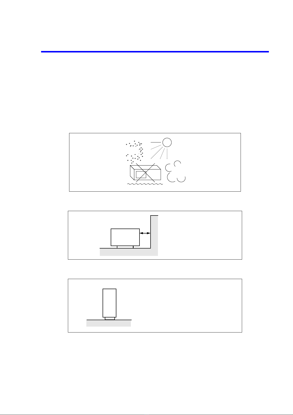
• Basic Precautions
Please observe the following precautions to prevent fire, burn, electric shock, and personal inju-
ry.
• Use a power cable rated for the voltage in question. Be sure however to use a power cable
conforming to safety standards of your nation when using a product overseas.
• When inserting the plug into the electrical outlet, first turn the power switch OFF and then
insert the plug as far as it will go.
• When removing the plug from the electrical outlet, first turn the power switch OFF and then
pull it out by gripping the plug. Do not pull on the power cable itself. Make sure your hands
are dry at this time.
• Before turning on the power, be sure to check that the supply voltage matches the voltage
requirements of the instrument.
• Connect the power cable to a power outlet that is connected to a protected ground terminal.
Grounding will be defeated if you use an extension cord which does not include a protective
conductor terminal.
• Be sure to use fuses rated for the voltage in question.
• Do not use this instrument with the case open.
• Do not place anything on the product and do not apply excessive pressure to the product. Al-
so, do not place flower pots or other containers containing liquid such as chemicals near this
Safety Summary

Safety Summary
Safety-2 FOE-ANZENA00
product.
• When the product has ventilation outlets, do not stick or drop metal or easily flammable ob-
jects into the ventilation outlets.
• When using the product on a cart, fix it with belts to avoid its drop.
• When connecting the product to peripheral equipment, turn the power off.
• Caution Symbols Used Within this Manual
Symbols indicating items requiring caution which are used in this manual are shown below to-
gether with their meaning.
DANGER: Indicates an item where there is a danger of serious personal injury (death or seri-
ous injury).
WARNING: Indicates an item relating to personal safety or health.
CAUTION: Indicates an item relating to possible damage to the product or instrument or relat-
ing to a restriction on operation.
• Safety Marks on the Product
The following safety marks can be found on ADC products.
: ATTENTION - Refer to manual.
: Protective ground (earth) terminal.
: DANGER - High voltage.
: CAUTION - Risk of electric shock.
• Replacing Parts with Limited Life
The following parts used in the instrument are main parts with limited life.
Replace the parts listed below before their expected lifespan has expired to maintain the perfor-
mance and function of the instrument.
Note that the estimated lifespan for the parts listed below may be shortened by factors such as
the environment where the instrument is stored or used, and how often the instrument is used.
The parts inside are not user-replaceable. For a part replacement, please contact the ADC sales
office for servicing.
Each product may use parts with limited life.
For more information, refer to the section in this document where the parts with limited life are
described.

Safety Summary
Safety-3
FOE-ANZENA00
Main Parts with Limited Life
• Hard Disk Mounted Products
The operational warnings are listed below.
• Do not move, shock and vibrate the product while the power is turned on.
Reading or writing data in the hard disk unit is performed with the memory disk turning at a
high speed. It is a very delicate process.
• Store and operate the products under the following environmental conditions.
An area with no sudden temperature changes.
An area away from shock or vibrations.
An area free from moisture, dirt, or dust.
An area away from magnets or an instrument which generates a magnetic field.
• Make back-ups of important data.
The data stored in the disk may become damaged if the product is mishandled. The hard disc
has a limited life span which depends on the operational conditions. Note that there is no
guarantee for any loss of data.
• Precautions when Disposing of this Instrument
When disposing of harmful substances, be sure dispose of them properly with abiding by the
state-provided law.
Harmful substances: (1) PCB (polycarbon biphenyl)
(2) Mercury
(3) Ni-Cd (nickel cadmium)
(4) Other
Items possessing cyan, organic phosphorous and hexadic chromium
and items which may leak cadmium or arsenic (excluding lead in sol-
der).
Example: fluorescent tubes, batteries
Part name Life
Unit power supply 5 years
Fan motor 5 years
Electrolytic capacitor 5 years
LCD display 6 years
LCD backlight 2.5 years
Floppy disk drive 5 years
Memory backup battery 5 years

Environmental Conditions
Safety-4 FOE-ANZENA00
This instrument should be only be used in an area which satisfies the following conditions:
• An area free from corrosive gas
• An area away from direct sunlight
• A dust-free area
• An area free from vibrations
• Altitude of up to 2000 m
Figure-1 Environmental Conditions
• Operating position
Figure-2 Operating Position
• Storage position
Figure-3 Storage Position
• The classification of the transient over-voltage, which exists typically in the main power supply, and
the pollution degree is defined by IEC61010-1 and described below.
Impulse withstand voltage (over-voltage) category II defined by IEC60364-4-443
Pollution Degree 2
Vibration
Direct sunlight
Corrosive
gas
Dust
Front
The instrument must be used in a hor-
izontal position.
To prevent the internal temperature
from rising, cooling fans are installed
in some instruments.
The air vents on the case must be un-
blocked.
A clear space of 10 centimeters or more
must be kept around the air vents.
Front
This instrument should be stored in a horizontal
position.
When placed in a vertical (upright) position for
storage or transportation, ensure the instrument is
stable and secure.
-Ensure the instrument is stable.
-Pay special attention not to fall.

Safety-5
Types of Power Cable
FOE-ANZENA00
Replace any references to the power cable type, according to the following table, with the appropriate power cable
type for your country.
Plug configuration Standards Rating, color
and length
Model number
(Option number)
PSE: Japan
Electrical Appliance and
Material Safety Law
125 V at 7 A
Black
2 m (6 ft)
Straight: A01402
Angled: A01412
UL: United States of America
CSA: Canada
125 V at 7 A
Black
2 m (6 ft)
Straight: A01403
(Option 95)
Angled: A01413
CEE: Europe
DEMKO: Denmark
NEMKO: Norway
VDE: Germany
KEMA: The Netherlands
CEBEC: Belgium
OVE: Austria
FIMKO: Finland
SEMKO: Sweden
250 V at 6 A
Gray
2 m (6 ft)
Straight: A01404
(Option 96)
Angled: A01414
SEV: Switzerland 250 V at 6 A
Gray
2 m (6 ft)
Straight: A01405
(Option 97)
Angled: A01415
SAA: Australia, New Zealand 250 V at 6 A
Gray
2 m (6 ft)
Straight: A01406
(Option 98)
Angled: ---------
BS: United Kingdom 250 V at 6 A
Black
2 m (6 ft)
Straight: A01407
(Option 99)
Angled: A01417
CCC:China 250 V at 10 A
Black
2 m (6 ft)
Straight: A114009
(Option 94)
Angled: A114109


Certificate of Conformity
This is to certify, that
complies with the provisions of the EMC Directive 2004/108/EC in accordance with EN61326
and Low Voltage Directive 2006/95/EC in accordance with EN61010.
ADC Corp. ROHDE&SCHWARZ
Japan International Operations GmbH
Munich, Germany
instrument, type, designation
6241A/42.00
DC Voltage Current Source/Monitor
6241A, 6242


6241A/6242 DC Voltage Current Source/Monitor Operation Manual
C-1
TABLE OF CONTENTS
1. PREFACE ...................................................................................................... 1-1
1.1 Product Overview .............................................................................................. 1-1
1.2 Supplied Accessories ........................................................................................ 1-2
1.3 Optional Accessories ......................................................................................... 1-3
1.4 Operating Environment ..................................................................................... 1-4
1.4.1 Environmental Conditions .......................................................................... 1-4
1.4.2 Power Specification .................................................................................... 1-6
1.4.3 Changing Power Voltage, and Checking and Replacing Power Fuse ........ 1-7
1.4.4 Power Cable ................................................................................................ 1-8
1.5 Operating Check ................................................................................................ 1-9
1.6 Cleaning, Storage, and Transport Methods ....................................................... 1-12
1.6.1 Cleaning ...................................................................................................... 1-12
1.6.2 Storage ........................................................................................................ 1-12
1.6.3 Transport ..................................................................................................... 1-12
1.7 Warm-up Time .................................................................................................. 1-13
1.8 Calibration ......................................................................................................... 1-13
1.9 Life Limited Parts ............................................................................................. 1-13
1.10 Product Disposal and Recycling ....................................................................... 1-14
2. OPERATION ................................................................................................ 2-1
2.1 Panel Descriptions ............................................................................................. 2-1
2.1.1 Front Panel .................................................................................................. 2-2
2.1.1.1 Display Section ........................................................................................... 2-3
2.1.1.2 SOURCE Section ....................................................................................... 2-3
2.1.1.3 SOURCE RANGE Section ......................................................................... 2-4
2.1.1.4 MEASURE Section .................................................................................... 2-4
2.1.1.5 OUTPUT CONTROL Section ................................................................... 2-5
2.1.1.6 TRIGGER Section ...................................................................................... 2-5
2.1.1.7 Other Keys .................................................................................................. 2-6
2.1.1.8 Output Section ............................................................................................ 2-7
2.1.1.9 POWER Switch .......................................................................................... 2-7
2.1.2 Screen Display (Annotations) ..................................................................... 2-8
2.1.3 Rear Panel ................................................................................................... 2-11
2.2 Basic Operation ................................................................................................. 2-13
2.2.1 Setting Source Value .................................................................................. 2-13
2.2.1.1 Relation between Keys ............................................................................... 2-13
2.2.1.2 Setting Source Value Using Cursor Keys/Rotary Knob
(when FIT Indicator is OFF) ...................................................................... 2-14
2.2.1.3 Setting Source Value Using Cursor Keys/Rotary Knob
(when FIT Indicator is ON) ........................................................................ 2-18
2.2.1.4 Setting Source Value using Direct Input Mode .......................................... 2-19
2.2.2 Setting Limiter Value ................................................................................. 2-21
2.2.3 Menu Operation .......................................................................................... 2-25
2.2.3.1 Method of Menu Operation ........................................................................ 2-25
2.2.3.2 Menu Structure and Parameter Setting ....................................................... 2-28
2.2.4 Initializing Setting Conditions .................................................................... 2-34
TABLE OF CONTENTS

6241A/6242 DC Voltage Current Source/Monitor Operation Manual
Table of Contents
C-2
2.2.5 DC Measurement ........................................................................................ 2-35
2.2.6 Pulse Measurement ..................................................................................... 2-39
2.2.7 Sweep Measurement ................................................................................... 2-43
2.3 Saving and Loading Parameters ........................................................................ 2-48
2.3.1 Auto Load at Power On .............................................................................. 2-48
2.3.2 Saving Parameters ...................................................................................... 2-48
2.3.3 Loading Parameters .................................................................................... 2-49
3. MEASUREMENT EXAMPLE ................................................................ 3-1
3.1 Measurement of Diode ...................................................................................... 3-1
3.2 Battery Charge and Discharge Test ................................................................... 3-3
4. REFERENCE ................................................................................................ 4-1
4.1 Menu Index ....................................................................................................... 4-1
4.2 Function Description ......................................................................................... 4-3
4.2.1 AUTO Key (Measurement Range) ............................................................. 4-3
4.2.2 DOWN Key (Source Range) ...................................................................... 4-3
4.2.3 FIT Key (Source Range) ............................................................................ 4-3
4.2.4 HOLD Key (Trigger Mode) ....................................................................... 4-4
4.2.5 LIMIT Key (Limiter Setting) ..................................................................... 4-4
4.2.6 MENU Key (Parameter Setting) ................................................................ 4-4
4.2.7 MODE Key (Source Mode) ........................................................................ 4-15
4.2.8 MON Key (Measurement Mode) ............................................................... 4-15
4.2.9 NULL/SEL key .......................................................................................... 4-15
4.2.10 OPR/SUSPEND (Operating/Suspend) ....................................................... 4-16
4.2.11 SHIFT/LOCAL (Shift Mode/Local) ........................................................... 4-16
4.2.12 STBY Key (Output Standby) ..................................................................... 4-17
4.2.13 TRIG/SWP STOP (Trigger/Sweep Stop) ................................................... 4-17
4.2.14 UP Key (Increasing the Source Range) ...................................................... 4-17
4.2.15 VS/IS Key (Source Function) ..................................................................... 4-18
4.2.16 123... Key (Direct Input Mode) .................................................................. 4-18
4.2.17 4W/2W Key (Remote Sensing Selection) .................................................. 4-18
5. TECHNICAL REFERENCES .................................................................. 5-1
5.1 DUT Connection ............................................................................................... 5-1
5.1.1 Note for Output Terminals ......................................................................... 5-1
5.1.2 Remote Sensing (2-wire or 4-wire Connection) ......................................... 5-2
5.1.3 Preventing Oscillation ................................................................................ 5-4
5.1.3.1 Preventing 6241A/6242 Oscillation ........................................................... 5-4
5.1.3.2 Oscillation from the Device Itself .............................................................. 5-5
5.1.4 Connection for High Current Measurement ............................................... 5-6
5.1.5 Connecting with the Fixture 12701A ......................................................... 5-7
5.2 Functions in Detail ............................................................................................ 5-8
5.2.1 DC Source Mode Operation ....................................................................... 5-8
5.2.2 Pulse Source Mode Operation .................................................................... 5-10
5.2.3 Sweep Source Mode Operation .................................................................. 5-12
5.2.3.1 DC Sweep Source Mode Operation ........................................................... 5-15
5.2.3.2 Pulse Sweep Source Mode Operation ........................................................ 5-17

6241A/6242 DC Voltage Current Source/Monitor Operation Manual
Table of Contents
C-3
5.2.3.3 Random Sweep and Random Pulse Sweep ................................................ 5-18
5.2.3.4 Two Slope Linear Sweep ............................................................................ 5-19
5.2.3.5 Reverse Function ........................................................................................ 5-20
5.2.3.6 RTB Function ............................................................................................. 5-21
5.2.4 Source Function .......................................................................................... 5-22
5.2.4.1 Source Mode, Source Function, and Setting Parameters ........................... 5-22
5.2.4.2 Restrictions on Changing Source Function ................................................ 5-23
5.2.4.3 Source Range .............................................................................................. 5-23
5.2.4.4 Suspend Function ....................................................................................... 5-25
5.2.5 Measurement Function ............................................................................... 5-28
5.2.5.1 Measurement Function ............................................................................... 5-28
5.2.5.2 Measurement Ranging ................................................................................ 5-29
5.2.5.3 Measurement Delay Time and Measurement Value .................................. 5-34
5.2.5.4 Measuring in Sample Hold Mode ............................................................... 5-35
5.2.5.5 Auto Zero Function .................................................................................... 5-36
5.2.5.6 Switching Unit Display .............................................................................. 5-37
5.2.6 Limiter (Compliance) ................................................................................. 5-38
5.2.6.1 Limiter Setting Ranges ............................................................................... 5-38
5.2.6.2 Setting the Limiter ...................................................................................... 5-39
5.2.6.3 Displaying and Outputting of Limiter Detection ........................................ 5-40
5.2.7 Alarm Detection ......................................................................................... 5-40
5.2.8 Source Timing and Measurement Timing .................................................. 5-41
5.2.8.1 Restriction on Time Parameter ................................................................... 5-42
5.2.8.2 Measurement Delay and Settling Time ...................................................... 5-44
5.2.8.3 Integration Time and Measurement Time .................................................. 5-47
5.2.8.4 Auto Range Delay ...................................................................................... 5-47
5.2.9 Calculation Functions ................................................................................. 5-49
5.2.9.1 NULL Calculation ...................................................................................... 5-49
5.2.9.2 Scaling Calculation ..................................................................................... 5-50
5.2.9.3 Comparator Calculation .............................................................................. 5-51
5.2.9.4 Max/Min Calculation .................................................................................. 5-52
5.2.10 External Control Signals ............................................................................. 5-53
5.2.10.1 Restrictions on Using External Trigger ...................................................... 5-54
5.2.10.2 Control of Scanner ...................................................................................... 5-57
5.2.11 Operating Multiple 6241A/6242 ................................................................ 5-58
5.2.11.1 Synchronized Operation ............................................................................. 5-58
5.2.11.2 Serial Connection ....................................................................................... 5-61
5.2.11.3 Parallel Connection .................................................................................... 5-62
5.2.12 Measurement Data Storing Function .......................................................... 5-63
5.2.12.1 Storing Measured Data into Data Memory (Memory Store) ...................... 5-63
5.2.13 Clearing Saved Data (Memory Clear) ........................................................ 5-64
5.2.14 Error log ...................................................................................................... 5-65
5.2.15 Self Test ...................................................................................................... 5-66
5.3 Compatibility with 6243/44 .............................................................................. 5-69
5.3.1 Remote Command Compatibility ............................................................... 5-69
5.3.2 Difference of Period-Parameters in Pulse Source Mode and
Sweep Source Mode ................................................................................... 5-69
5.3.3 Notes for Synchronous Operation .............................................................. 5-70
5.4 Operational Principles ....................................................................................... 5-71
5.4.1 Block Diagram ............................................................................................ 5-71

6241A/6242 DC Voltage Current Source/Monitor Operation Manual
Table of Contents
C-4
5.4.2 Operational Principles ................................................................................ 5-71
6. REMOTE PROGRAMMING ................................................................... 6-1
6.1 Using an Interface ............................................................................................. 6-1
6.1.1 Selecting the Interface ................................................................................ 6-1
6.2 Remote Command Index ................................................................................... 6-2
6.3 GPIB .................................................................................................................. 6-5
6.3.1 Overview .................................................................................................... 6-5
6.3.2 Precautions when Using GPIB ................................................................... 6-6
6.3.3 Setting GPIB ............................................................................................... 6-7
6.4 USB ................................................................................................................... 6-8
6.4.1 Overview .................................................................................................... 6-8
6.4.2 USB Specifications ..................................................................................... 6-8
6.4.3 USB Setup .................................................................................................. 6-8
6.4.3.1 Connection to PC ........................................................................................ 6-8
6.4.3.2 USB Id Setup .............................................................................................. 6-9
6.4.3.3 Precautions when Using USB .................................................................... 6-9
6.5 Status Register Structure ................................................................................... 6-10
6.6 Data Output Format (Talker Format) ................................................................ 6-18
6.7 Remote Command ............................................................................................. 6-22
6.7.1 Command Syntax ....................................................................................... 6-22
6.7.2 Data Format ................................................................................................ 6-23
6.7.3 Remote Command List ............................................................................... 6-24
6.7.4 TER? Command ......................................................................................... 6-40
6.8 Sample Programs .............................................................................................. 6-41
6.8.1 Programming Examples with GPIB ........................................................... 6-41
6.8.1.1 Programming Example 1: DC Measurement ............................................. 6-41
6.8.1.2 Programming Example 2: Pulse Measurement .......................................... 6-43
6.8.1.3 Programming Example 3: Sweep Measurement ........................................ 6-44
6.8.1.4 Programming Example 4: Using Measurement Buffer Memory ............... 6-46
6.8.2 Programming Examples with USB ............................................................ 6-48
6.8.2.1 Programming Example: DC Measurement ................................................ 6-48
7. PERFORMANCE TEST ............................................................................ 7-1
7.1 6241A Tests ...................................................................................................... 7-1
7.1.1 Measuring Instruments Required for Performance Tests ........................... 7-1
7.1.2 Connection .................................................................................................. 7-1
7.1.3 Test Methods .............................................................................................. 7-1
7.2 6242 Tests ......................................................................................................... 7-3
7.2.1 Measuring Instruments Required for Performance Tests ........................... 7-3
7.2.2 Connection .................................................................................................. 7-3
7.2.3 Test Methods .............................................................................................. 7-3
8. CALIBRATION ........................................................................................... 8-1
8.1 6241A Calibration ............................................................................................. 8-1
8.1.1 Cables and Measuring Instruments Required for Calibration .................... 8-1
8.1.2 Safety Precautions ...................................................................................... 8-2

6241A/6242 DC Voltage Current Source/Monitor Operation Manual
Table of Contents
C-5
8.1.3 Connections ................................................................................................ 8-2
8.1.4 Calibration Points and Tolerance Range .................................................... 8-3
8.1.5 Calibrating Operation ................................................................................. 8-5
8.1.5.1 Calibration Procedure ................................................................................. 8-10
8.1.5.2 Voltage-source and Voltage-limiter Calibration ........................................ 8-10
8.1.5.3 Voltage-measurement Calibration .............................................................. 8-11
8.1.5.4 Current-source and Current-limiter Calibration ......................................... 8-12
8.1.5.5 Current-measurement Calibration .............................................................. 8-12
8.2 6242 Calibration ................................................................................................ 8-13
8.2.1 Cables and Measuring Instruments Required for Calibration .................... 8-13
8.2.2 Safety Precautions ...................................................................................... 8-14
8.2.3 Connections ................................................................................................ 8-15
8.2.4 Calibration Points and Tolerance Range .................................................... 8-16
8.2.5 Calibrating Operation ................................................................................. 8-18
8.2.5.1 Calibration Procedure ................................................................................. 8-25
8.2.5.2 Voltage-source and Voltage-limiter Calibration ........................................ 8-25
8.2.5.3 Voltage-measurement Calibration .............................................................. 8-26
8.2.5.4 Current-source and Current-limiter Calibration (30 µA to 300 mA) ......... 8-26
8.2.5.5 Current-source and Current-limiter Calibration, (3 A, 5 A) ....................... 8-27
8.2.5.6 Current-measurement Calibration (30 µA to 300 mA) .............................. 8-28
8.2.5.7 Current-measurement Calibration (3 A, 5 A) ............................................. 8-28
9. SPECIFICATIONS ...................................................................................... 9-1
9.1 Source and Measurement .................................................................................. 9-1
9.1.1 6241A Source and Measurement ................................................................ 9-1
9.1.2 6242 Source and Measurement .................................................................. 9-8
9.2 Source and Measurement Function ................................................................... 9-16
9.3 Set Time ............................................................................................................ 9-17
9.4 General Specification ........................................................................................ 9-19
APPENDIX ................................................................................................................. A-1
A.1 When Problems Occur (Before Requesting Repairs) ........................................ A-1
A.2 Error Message List ............................................................................................ A-3
A.3 Execution Time ................................................................................................. A-7
A.3.1 GPIB/USB Remote Execution Time (Typical Value) ................................ A-7
A.3.2 Internal Processing Time (Typical Value) ................................................. A-11
DIMENSIONAL OUTLINE DRAWING........................................................... EXT-1
ALPHABETICAL INDEX ..................................................................................... I-1


F-1
6241A/6242 DC Voltage Current Source/Monitor Operation Manual
LIST OF ILLUSTRATIONS
No. Title Page
1-1 Operating Environment ..................................................................................................... 1-5
1-2 Set Power Voltage Indicator ............................................................................................. 1-6
1-3 Power Cable ...................................................................................................................... 1-8
1-4 Connecting the Power Cable ............................................................................................. 1-9
1-5 Screen Displaying Self-Test ............................................................................................. 1-9
1-6 Screen Displaying Self-Test Completion ......................................................................... 1-10
1-7 Start-up Screen .................................................................................................................. 1-10
1-8 VSVM Measurement (In output OFF Standby) ............................................................... 1-10
1-9 Displaying VSVM 300 mV Range, 0 V Measurement .................................................... 1-11
2-1 Front Panel ........................................................................................................................ 2-2
2-2 Display Section ................................................................................................................. 2-3
2-3 SOURCE Section .............................................................................................................. 2-3
2-4 SOURCE RANGE Section ............................................................................................... 2-4
2-5 MEASURE Section .......................................................................................................... 2-4
2-6 OUTPUT CONTROL Section .......................................................................................... 2-5
2-7 TRIGGER Section ............................................................................................................2-5
2-8 Other Keys ........................................................................................................................ 2-6
2-9 Output Section .................................................................................................................. 2-7
2-10 POWER Switch ................................................................................................................ 2-7
2-11 Screen Display (Annotations) ........................................................................................... 2-8
2-12 Rear Panel ......................................................................................................................... 2-11
2-13 Relation between Keys .....................................................................................................2-13
2-14 Menu Operation Overview ............................................................................................... 2-26
2-15 DC Measurement .............................................................................................................. 2-35
2-16 Pulse Measurement ........................................................................................................... 2-39
2-17 Sweep Measurement .........................................................................................................2-43
3-1 Diode Measurement Connection ...................................................................................... 3-2
3-2 Waveform of Battery Discharging Test ............................................................................ 3-4
3-3 Battery Charge Discharge Test Connection ...................................................................... 3-5
4-1 Linear Sweep .................................................................................................................... 4-6
4-2 Fixed Sweep ...................................................................................................................... 4-6
4-3 Two Slope Linear Sweep .................................................................................................. 4-7
4-4 STBY In ............................................................................................................................ 4-11
4-5 InterLock In ...................................................................................................................... 4-11
4-6 Operate Out ....................................................................................................................... 4-11
4-7 OPR/SUS In ...................................................................................................................... 4-12
4-8 OPR/STBY In ................................................................................................................... 4-12
5-1 Internal Wire Connection .................................................................................................. 5-1
5-2 2-Wire and 4-Wire Connections ....................................................................................... 5-2
5-3 Reducing Stray Capacitance and Lead Inductor ............................................................... 5-4
5-4 Preventing Device Oscillation .......................................................................................... 5-5
5-5 6241A/6242 Oscillation Countermeasures ....................................................................... 5-5

F-2
6241A/6242 DC Voltage Current Source/Monitor Operation Manual
List of Illustrations
No. Title Page
5-6 Connection for High Current Measurement ..................................................................... 5-6
5-7 Connection with the 12701A ............................................................................................ 5-7
5-8 Random Sweep and Random Pulse Sweep ....................................................................... 5-18
5-9 Two Slope Linear Sweep .................................................................................................. 5-19
5-10 Two Slope Linear Pulse Sweep ........................................................................................ 5-19
5-11 Concept of Output Status ..................................................................................................5-25
5-12 Measuring in Sample Hold Mode ..................................................................................... 5-35
5-13 Rechargeable Battery Charge and Discharge Operations ................................................. 5-39
5-14 NULL Calculation Timing ................................................................................................ 5-49
5-15 Control of Scanner ............................................................................................................ 5-57
5-16 Serial Connection .............................................................................................................. 5-61
5-17 Parallel Connection ........................................................................................................... 5-62
5-18 Conceptual Diagram of Storing Measured Data ............................................................... 5-63
5-19 Self-test Operation ............................................................................................................ 5-68
6-1 Structure of Status Register .............................................................................................. 6-11
6-2 Structure of Status Byte Register ...................................................................................... 6-12
8-1 Connections for 6241A Calibration .................................................................................. 8-2
8-2 6241A Calibration Procedure (1) ...................................................................................... 8-5
8-3 6241A Calibration Procedure (2) ...................................................................................... 8-6
8-4 6241A Calibration Procedure (3) ...................................................................................... 8-7
8-5 6241A Calibration Procedure (4) ...................................................................................... 8-8
8-6 6241A Calibration Procedure (5) ...................................................................................... 8-9
8-7 6242 Connections for Calibration ..................................................................................... 8-15
8-8 6242 Calibration Procedure (1) ......................................................................................... 8-18
8-9 6242 Calibration Procedure (2) ......................................................................................... 8-19
8-10 6242 Calibration Procedure (3) ......................................................................................... 8-20
8-11 6242 Calibration Procedure (4) ......................................................................................... 8-21
8-12 6242 Calibration Procedure (5) ......................................................................................... 8-22
8-13 6242 Calibration Procedure (6) ......................................................................................... 8-23
8-14 6242 Calibration Procedure (7) ......................................................................................... 8-24

T-1
6241A/6242 DC Voltage Current Source/Monitor Operation Manual
LIST OF TABLES
No. Title Page
1-1 Standard Accessory List ................................................................................................... 1-2
1-2 Optional Accessory List ....................................................................................................1-3
1-3 Power Supply Specification .............................................................................................. 1-6
2-1 Keys and Menu Functions ................................................................................................ 2-27
5-1 Tolerable Current and Wire Thickness ............................................................................. 5-6
5-2 DC Source Mode Operation ............................................................................................. 5-8
5-3 Pulse Source Mode Operation .......................................................................................... 5-10
5-4 Sweep Source Mode Operation ........................................................................................ 5-12
5-5 DC Sweep Source Mode ................................................................................................... 5-15
5-6 Pulse Sweep Source Mode Operation ............................................................................... 5-17
5-7 Reverse Operation at DC Sweep ...................................................................................... 5-20
5-8 Reverse Operation at Pulse Sweep ................................................................................... 5-21
5-9 Relation between Prefix of the Unit and Digit ................................................................. 5-37
5-10 Alarm Detection Contents ................................................................................................ 5-40
5-11 Source Mode and Time Parameters to be Considered ...................................................... 5-41
5-12 External Control Signal Functions .................................................................................... 5-53
5-13 Restrictions on Tp, Tp (ext), Th, and Th (ext) .................................................................. 5-54
5-14 TA Value ........................................................................................................................... 5-55
5-15 Restriction on Top ............................................................................................................ 5-55
5-16 Comparison of Storing Measured Data ............................................................................ 5-64
5-17 Self-test Items ................................................................................................................... 5-66
6-1 Interface Function ............................................................................................................. 6-5
6-2 Standard Bus Cable ........................................................................................................... 6-6
6-3 Status Byte Register (STB) ............................................................................................... 6-13
6-4 Standard Event Status Register (ESR) .............................................................................. 6-14
6-5 Device Event Status Register (DSR) ................................................................................ 6-15
6-6 Error Register (ERR) ........................................................................................................ 6-17
A-1 Items to be Inspected before Requesting the Repair ......................................................... A-1
A-2 Error Message List ............................................................................................................ A-3

This manual suits for next models
1
Table of contents
Other ADCMT Monitor manuals