ADDAC 207 User manual

ADDAC207
INTUITIVE
QUANTIZER
USE
R'S
GUI
DE,
REV03

Welcome
to:
ADDAC207
INTUITIVE
QUANTIZER
USER'S
GUIDE
Revision.03
JullJ.2013
PAGE
INDEX
3.
OVERVIEW
4.
INTRODUCTION
5.
VCO's
SIMPLE
SETUP
6.
QUANTIZER
BABY
STEPS
7.
QUANTIZER
/
KEYBOARD
MODES
8.
KEY/
SCALE
SET
&
SETTINGS
9.
QUANTIZER
VOICES
INTUITIVE
MENU
10-13.
OVERVIEW
14-24.
EXAMPLES
14.
NOTES
2-3-4
-
EX.I
15.
QUANTIZATION
TYPE
-
EX.II
16.
GATE
LENGTH
-
EX.Ill
17.
TRIGGER
REPEAT
-
EX.IV
18.
REACTION
TIME
-
EX.V
19.
OCTAVE
OFFSET
-
EX.VI
20-23.
TUNING
-
EX.VII
24.
PRESETS
-
EX.VI
11
25-26.
ASSIGN
&
TRANSPOSE
27.
TUNING
RESET
28.
REMARKS
ON
TEMPERAMENTS
29.
MEMORY
&
TECH
SPECS
30.
HELPFUL
TABLES
ADDAC207
INTUITIVE
QUANTIZER
USER'S
GUIDE
Revision.03
JullJ.2013
INTUITIVE
QUANTIZER
ADDAC207
KEY
/OCTAVE
C2 1
'q-~
O!O
INTUITIVE
MENU
SET
KEY
T
00
2
3
po
D
NOTE
2 4
NOTE
3
L
IN
0
OUT
0
IN
:o
NOTE
4 0
I
GATE
IN
z
E
a
u
A
N
T
I
z
E
I
N
0
T
E
0
GATE
OUT
0
GATE
IN
0
2
GATE
OUT
0
OUT
ASSIGN
:::===::::::a=:::::==~
:o
•o L
OQO
7
'
00
·o
·-~~
·
PRESETS
2013
ADDAC
SYSTEM
ADDAC
Sl:ISTEM
page 3
IN
0
OUT
0
IN
0
OUT
T
I
z
E
I
N
0
T
E
GATE
IN
0
s
GATE
OUT
a
u
A
N
T
I
z
E
I
N
0
T
E
0
GATE
IN
0
4
GATE
OUT
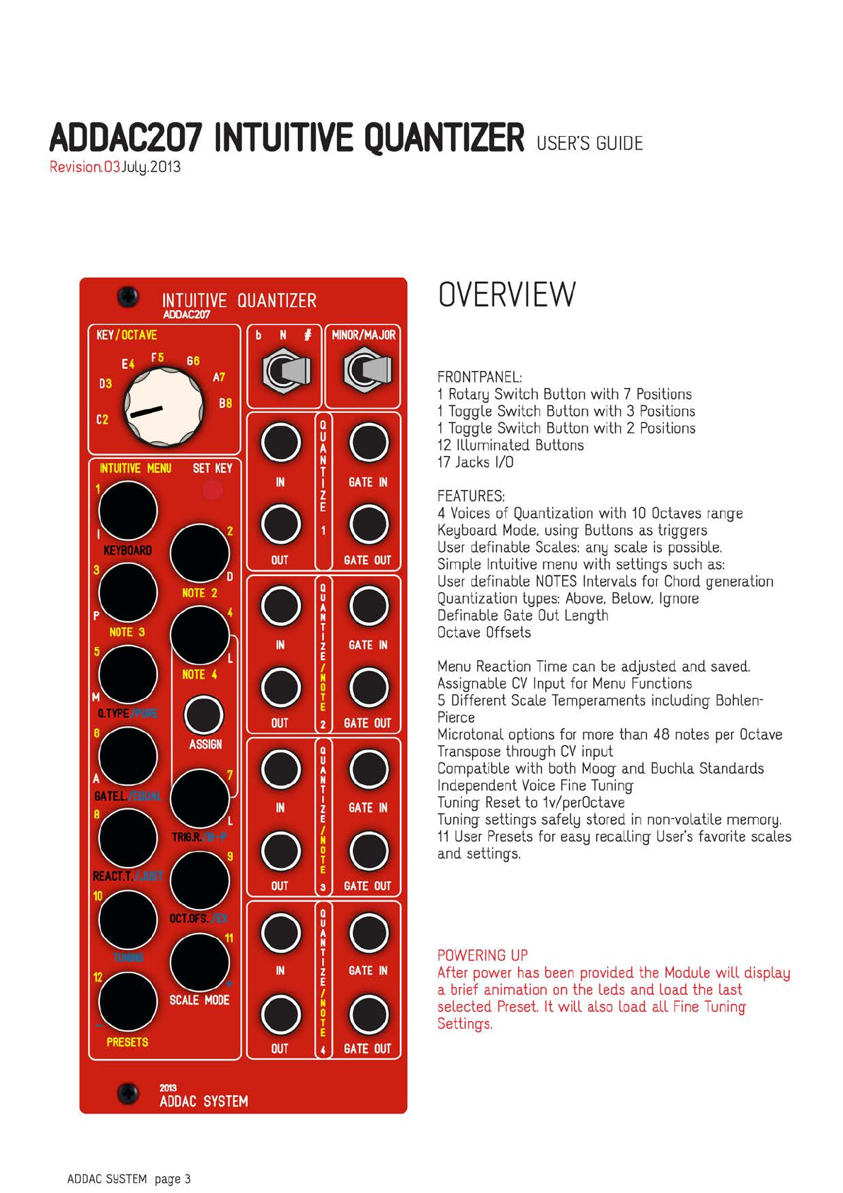
OVERVIEW
FRONTPANEL:
1
RotarlJ
Switch
Button
with 7
Positions
1
Toggle
Switch
Button
with 3
Positions
1
Toggle
Switch
Button
with 2
Positions
12
Illuminated
Buttons
17
Jacks
1/0
FEATURES:
4
Voices
of
Quantization
with
10
Octaves
range
KelJboard
Mode.
using
Buttons
as
triggers
User
definable
Scales:
anlJ
scale
is
possible.
Simple
Intuitive
menu
with settings
such
as:
User
definable
NOTES
Intervals
for
Chord
generation
Quantization
tlJpes:
Above.
Below.
Ignore
Definable
Gate
Out
Length
Octave
Offsets
Menu
Reaction
Time
can
be
adjusted
and
saved.
Assignable
CV
Input
for
Menu
Functions
5 Different
Scale
Temperaments
including
Bohlen-
Pierce
Microtonal
options
for
more
than
48
notes
per
Octave
Transpose
through
CV
input
Compatible
with
both
Moog
and
Buchla
Standards
Independent
Voice
Fine
Tuning
Tuning
Reset
to
1v/perOctave
Tuning
settings
safellJ
stored
in
non-volatile
memorlJ.
11
User
Presets
for
easlJ
recalling
User's
favorite
scales
and
settings.
POWERING
UP
After
power
has
been
provided
the
Module
will
displalJ
a
brief
animation
on
the
leds
and
load
the
last
selected
Preset.
It will
also
load all
Fine
Tuning
Settings.

ADDAC207
INTUITIVE
QUANTIZER
USER'S
GUIDE
Revision.03
JullJ.2013
INTUITIVE
QUANTIZER
ADDAC207
KEY
/OCTAVE
C2 1
'q-~
O!O
INTUITIVE
MENU
SET
KEY
T
00
2
3
po
D
NOTE
2 4
NOTE
3
L
IN
0
OUT
0
IN
:o
NOTE
4 0
I
GATE
IN
z
E
a
u
A
N
T
I
z
E
I
N
0
T
E
0
GATE
OUT
0
GATE
IN
0
2
GATE
OUT
0
OUT
ASSIGN
:::===::::::a=:::::==~
:o
•o L
OQO
7
'
00
·o
·-~~
·
PRESETS
2013
ADDAC
SYSTEM
ADDAC
Sl:ISTEM
page 4
IN
0
OUT
0
IN
0
OUT
T
I
z
E
I
N
0
T
E
GATE
IN
0
s
GATE
OUT
a
u
A
N
T
I
z
E
I
N
0
T
E
0
GATE
IN
0
4
GATE
OUT
INTRODUCTION
We
know
this
Guide
it's
not
the
best
literature
we
could
be
reading
but
it will
be
extremellJ
important
to
have
an
overall
understanding all
of
the
fundamental
operational
procedures
and
getting full potential
out
of
it.
So
we
fulllJ
recommend
that
lJOU
read
the
whole
document at
some
point.
most
things
lJOU'll
onllJ
need
to
read
once.
cause
once
lJOU
understand
the
opera-
tional
procedures
everlJ
feature
is
right
there
at
the
tip
of
lJOUr
fingers.
Nevertheless
lJOU
can
start
blJ
reading
the
first
pages
that will
alreadlJ
put
lJOU
up
and
quantizing.
ADDAC207
INTUITIVE
QUANTIZER
USER'S
GUIDE
Revision.03
JullJ.2013
ADDAC
Sl:ISTEM
page 5
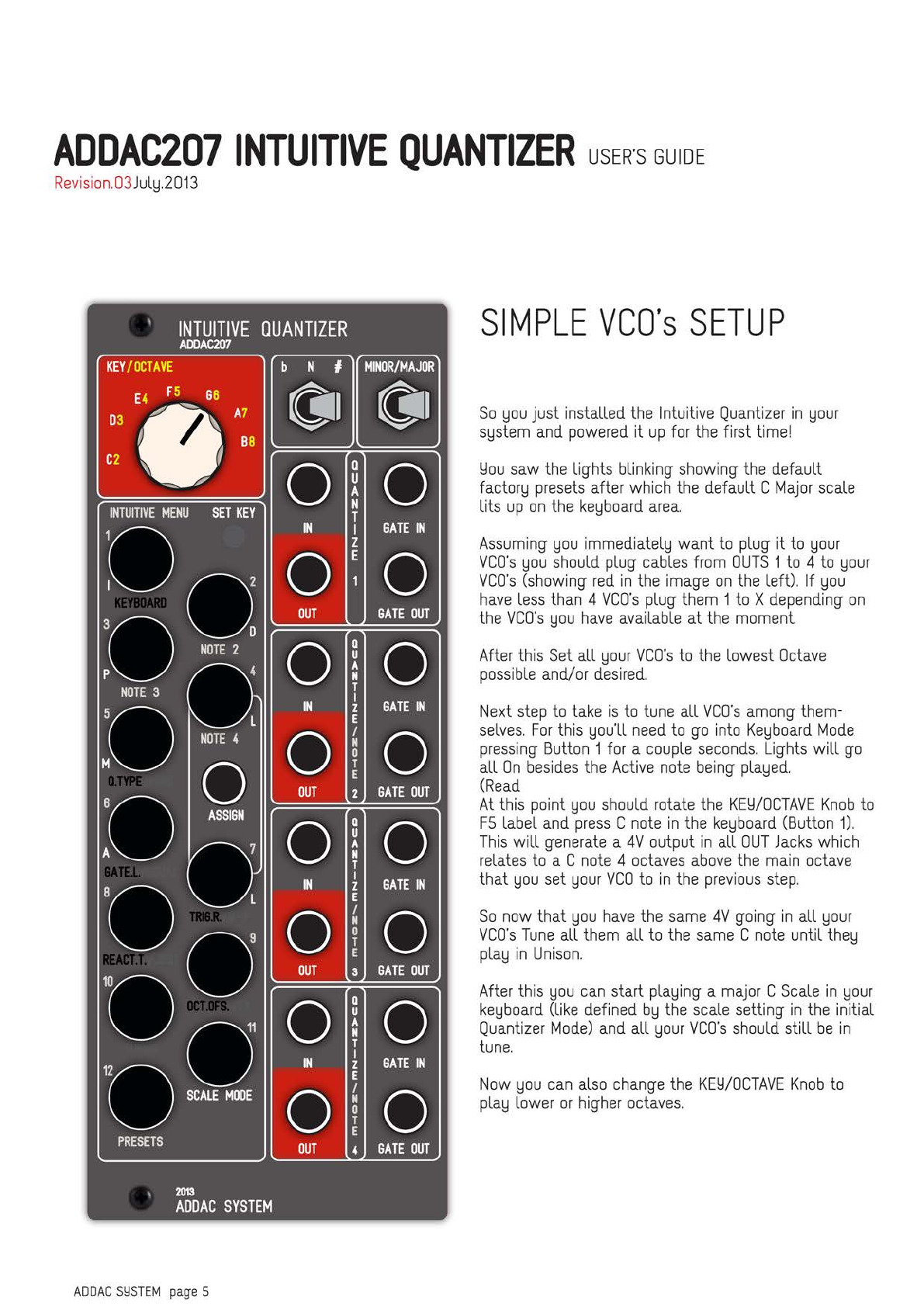
SIMPLE
VCO's
SETUP
So
lJOU
just installed
the
Intuitive
Quantizer
in
lJOUr
SlJstem
and
powered
it
up
for
the
first
time!
Llou
saw
the
lights blinking
showing
the
default
factorlJ
presets
after
which
the
default C
Major
scale
lits
up
on
the
kelJboard
area.
Assuming
lJOU
immediatellJ
want
to
plug it
to
lJOUr
VCO's
lJOU
should
plug
cables
from
OUTS
1
to
4
to
lJOUr
VCO's
(showing
red
in
the
image
on
the
left). If
lJOU
have
less
than
4
VCO's
plug
them
1
to
X
depending
on
the
VCO's
lJOU
have
available
at
the
moment.
After
this
Set
all
lJour
VCO's
to
the
lowest
Octave
possible
and/or
desired.
Next
step
to
take
is
to
tune
all
VCO's
among
them-
selves.
For
this
lJOU'll
need
to
go
into
KelJboard
Mode
pressing
Button
1
for
a
couple
seconds.
Lights
will
go
all
On
besides
the
Active
note
being
plalJed.
(Read
At
this
point
lJOU
should
rotate
the
KELl/OCTAVE
Knob
to
FS
label
and
press
C
note
in
the
kelJboard
(Button
1).
This
will
generate
a
4V
output
in
all
OUT
Jacks
which
relates
to
a C
note
4
octaves
above
the
main
octave
that
lJOU
set
lJOUr
VCO
to
in
the
previous
step.
So
now
that
lJOU
have
the
same
4V
going
in
all
lJour
VCO's
Tune
all
them
all
to
the
same
C
note
until
thelJ
plalJ
in
Unison.
After
this
lJOU
can
start
plalJing
a
major
C
Scale
in
lJOUr
kelJboard
(like
defined
blJ
the
scale
setting
in
the
initial
Quantizer
Mode)
and
all
lJour
VCO's
should
still
be
in
tune.
Now
lJOU
can
also
change
the
KELl/OCTAVE
Knob
to
plalJ
lower
or
higher
octaves.

ADDAC207
INTUITIVE
QUANTIZER
USER'S
GUIDE
Revision.03
JullJ.2O13
ADDAC
Sl:ISTEM
page 6
QUANTIZER
BAB~
STEPS
So
now
that
vco·s
are
tuned
we
want
to
start quantiz-
ing
some
signals.
First
we
need
to
get
out
of
KelJboard
Mode
back
to
Quantizer
Mode.
For
this
we
need
to
press
Button
I
for
a
couple
seconds.
Lights
will
change
and
displalJ
the
Active
Notes
selected,
should
still
show
C
Major
KelJ.
At
this
point
lJOU
should
plug
anlJ
CV
signal
into
IN
jack
of
NOTE
1
(top
left
jack).
lmmediatellJ
all
outputs
will
send
the
same
voltages
to
all
VCO's
and
thelJ
all
should
plalJ
tuned.
Now
we're
able
turn
notes
On
and
Off
blJ
pressing
the
corresponding
kelJboard
buttons.
After
this
we
could
also
plug
more
CV
signals
to
NOTE
2-3-4
Inputs
and
have
them
all quantizing a diferent
CV
source
to
the
same
scale.

ADDAC207
INTUITIVE
QUANTIZER
USER'S
GUIDE
Revision.O3
JullJ.2O13
ADDAC
Sl:ISTEM
page 7
QUANTIZER/
KE~BOARD
The
Intuitive
Quantizer
can
be
used
in
two
Main
Opera-
tion
Modes
QUANTIZER
and
KELlBOARD
selectable
through
the
Menu
and
described
further
ahead
in
this
document.
for
now
let's
explain
the
2
MAIN
MODES
:
QUANTIZER
MODE:
In
Quantizer
Mode
the
Input
Voltage
is
used
to
trigger
the
Quantization
Process
comparing
and
adjusting
the
input
voltage
to
the
closest
note
activellJ
selected.
Let's
call
these
sets
of
Active
Notes
the
Active
Scale.
The
Active
Scale.
represented
blJ
the
Menu
Buttons.
will
light
up
according
to
these
selected
notes
(drawn
in
red
in
the
image
on
the
left).
EverlJ
time a
new
note
is
quantized
on
Voice
I
the
correspondent
button will
blink
momentarillJ.
To
avoid
visual
confusion
other
Voices
will
not
blink.
KELlBOARD
MODE:
In
KelJboard
Mode
it's
the
User
who
manuallLl
controls
which
note
will
be
plalJing
It
acts
as
a
Monophonic
KelJboard
and
all
leds
are
lit
besides
the
one
note
plalJing.
Once
a
note
is
plalJed
the
output will
staLl
on
that
note
until
another
note
is
plalJed.
There
is
no
OFF
in
an
analogue
quantizer!
In
KelJboard
Mode.
if
the
user
is
using
Notes
intervals
to
generate
chords
it will
keep
the
same
notes
as
defined
in
Quantizer
Mode.
This
means
that
in
KelJboard
Mode
Notes
2-3-4
will still
respect
the
notes
selected
in
Quantizer
Mode
and
will
not
plalJ
anlJ
note
that
is
not
selected
in
Quantizer
Mode.
ADDAC207
INTUITIVE
QUANTIZER
USER'S
GUIDE
Revision.O3
JullJ.2O13
ADDAC
Sl:ISTEM
page 8
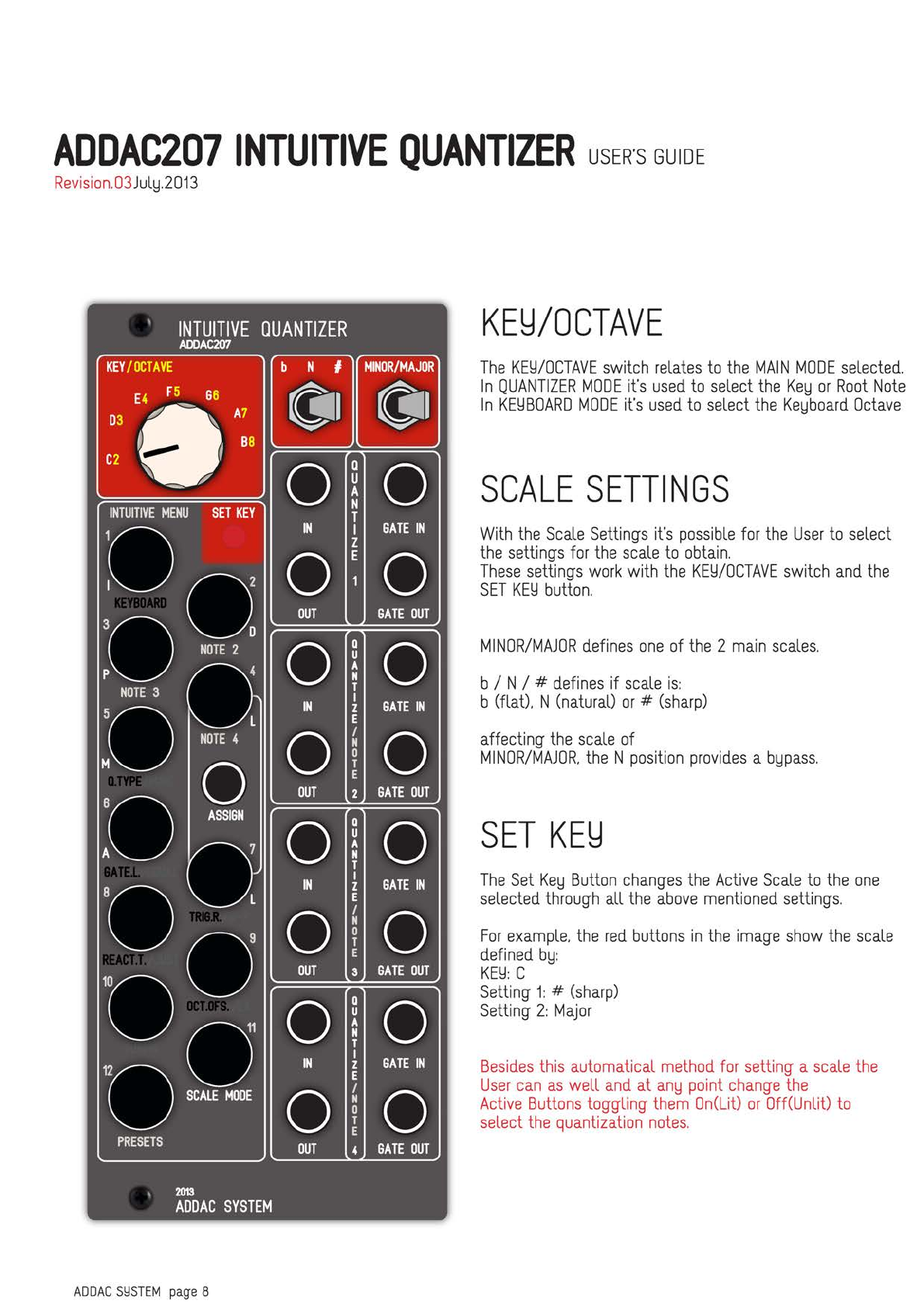
KE~/OCTAVE
The
Km/OCTAVE
switch
relates
to
the
MAIN
MODE
selected.
In
QUANTIZER
MODE
it's
used
to
select
the
KelJ
or
Root
Note
In
KmBOARD
MODE
it's
used
to
select
the
KelJboard
Octave
SCALE
SETTINGS
With
the
Scale
Settings
it's
possible
for
the
User
to
select
the
settings
for
the
scale
to
obtain.
These
settings
work
with
the
Km/OCTAVE
switch
and
the
SET
Km
button.
MINOR/MAJOR
defines
one
of
the
2
main
scales.
b / N/ #
defines
if
scale
is:
b (flat). N(natural)
or
#
(sharp)
affecting
the
scale
of
MINOR/MAJOR.
the
N
position
provides
a
blJpass.
SET
KE~
The
Set
KelJ
Button
changes
the
Active
Scale
to
the
one
selected
through
all
the
above
mentioned
settings.
For
example.
the
red
buttons
in
the
image
show
the
scale
defined
blJ:
Km:
C
Setting
1:
#
(sharp)
Setting
2:
Major
Besides
this automatical
method
for
setting a
scale
the
User
can
as
well
and
at
anlJ
point
change
the
Active
Buttons
toggling
them
On(Lit)
or
OffCUnlit)
to
select
the
quantization
notes.

ADDAC207
INTUITIVE
QUANTIZER
USER'S
GUIDE
Revision.03
JullJ.2013
INTUITIVE
QUANTIZER
ADDAC207
KEY
/OCTAVE
C2 ,
~-
~
0 !0
INTUITIVE
MENU
SET
KEY
T
00
2
3
po
D
NOTE
2 4
NOTE
3
L
IN
I
GATE
IN
z
0~
0
OUT
GATE
OUT
0 0
IN
GATE
IN
:o
NOTE
4 0
0
OUT
a
u
A
N
T
I
z
E
I
N
0
T
E 0
2
GATE
OUT
:o
•o L
ASSIGN
:::======
0
===::::'.:
OcO
7
DO
'O
•~n~
PRESETS
2013
ADDAC
SYSTEM
ADDAC
Sl:ISTEM
page 9
IN
0
OUT
0
IN
0
OUT
T
I
z
E
I
N
0
T
E
GATE
IN
0
3
GATE
OUT
a
u
A
N
T
I
z
E
I
N
0
T
E
0
GATE
IN
0
4
GATE
OUT
QUANTIZER
VOICES
1-4
There
are
4
Quantization
Voices.
these
can
be
used
either
lndependentellJ:
when
an
Input
is
plugged
in
the
IN
Jack
or
related
to
Voice
1:
when
no
input
is
connected
on
either
Voice
2.
3
or
4.
If
no
voltage input
is
used
voices
2.
3
and
4 will
automaticalllJ
relate
to
Voice
t
ThelJ
will
then
mirror
Voice
1
input
or
be
used
for
Chords
Generation
as
described
in
the
NOTE
2/3/
4
section
of
the
Intuitive
Menu
chapter.
Each
Voice
features
4jacks
1/0:
IN
(-Sv
+Sv):
Voltage
Input
for
Quantization
OUT
(Ov
+10v):
Quantized
Voltage
Output
GATE
IN
(0
+Sv):
Trigger
Input
for
External
Quantization
timing. If this
input
is
used
it
onllJ
Quan-
tizes
next
note
onllJ
when
a trigger
is
received.
If
it's
not
used
then
it will
quantize
depending
to
CV
changes
onllJ.
This
Gate
In
ON/OFF
detection
is
made
in
the
software.
After
the
detection
goes
On.
and
if
the
user
removes
the
gate
in
jack it will automaticalllJ
goes
to
Off
after
60
seconds.
If
the
user
want
to
reset
voices
before
the
60
seconds
period
Button
6
(Gate
U
can
be
pressed
at
the
same
time
as
the
voice
number
Button
(1
to
4).
For
example
to
Reset
voice
2
Gate
In.
the
user
needs
to
press
Button
2
and
6 at
the
same
time.
This
will
resume
the
behaviour
without
regarding
the
Gate
In
until a
new
jack
is
plugged
in.
GATE
OUT
(0
+Sv):
Gate
Output
for
ADSR's
Outputs
everlJtime
a
new
quantization
is
calculated.
It
respects
the
incoming
Trigger
Input
Gate.
while
it's
On
the
Gate
Out
will
remain
On.
The
Gate
Out
will
go
Off
when
Trigger
In
is
Off
and
the
Gate
Length
time
as
passed
as
described
in
the
Gate
Length
section
of
the
Intuitive
Menu
Chapter.

ADDAC207
INTUITIVE
QUANTIZER
USER'S
GUIDE
Revision.O3
JullJ.2O13
ADDAC
Sl:ISTEM
page
10
INTUITIVE
MENU
OVERALL
OPERATION
PROCEDURES
All
Quantizer
Operation
Settings
are
defined
through
the
same
Push-Buttons
as
Scale
selection
and
KelJboard.
For
Menu
related
Access
the
Push-Button
needs
to
be
pressed
for
aprox.
1
second
after
which
the
Leds
change
to
give
User
the
necessarlJ
feedback
to
acknowledge
his
input.
Once
this
happens
the
Module
is
alreadlJ
in
the
Menu
Windows
recalled
blJ
the
User.
In
these
Windows
lJOU'll
see
the
active
setting
identi-
fied
blJ
the
onllJ
button
that will
be
lit.
Pressing
a non-lit
button
changes
the
setting
to
that
selection
while,
at
the
same
time,
changes
the
lit
button
for
visual
feedback.
Pressing
a lit
button
is
alwalJS
the
confirmation
of
the
desired
setting
and
it automaticalllJ
jumps
out
of
the
Menu
Window
back
to
the
previous
Main
Mode
(QUANTIZER
/
KEldBOARD)
Window
changing
the
leds
as
well.
While
in
anlJ
Menu
Window,
after 5
seconds
of
inactiv-
itld
with
the
Menu
Buttons
the
Module
automaticalllJ
jumps
out
of
the
Menu
Window
back
to
the
previous
Main
Mode
(QUANTIZER/
KEldBOARD)
Window
chang-
ing
the
leds
as
well.
The
User
can
jump
to
Menu
Windows
from
inside
other
Menu
Windows
using
the
same
Press
and
Hold
for
aprox.
1
second
procedure.
However
if settings
were
changed
thelJ
will
not
be
saved.
COLOR
CODING
Buttons
are
numbered
in
ldellow
from
1
to
12,
other
color
engravings
are
coded
depending
on
their
func-
tion:
Black
is
used
for
Overall
settings
ldellow
is
used
for
Chords
Generation
Settings
Blue
is
used
for
Scale
Temeprament
and
Fine
Tunning
Settings
White
is
used
for
Scale
Mode
Settings
(lorian,
Dorian
..
.)
ADDAC207
INTUITIVE
QUANTIZER
USER'S
GUIDE
Revision.O3
JullJ.2O13
ADDAC
Sl:ISTEM
page
11
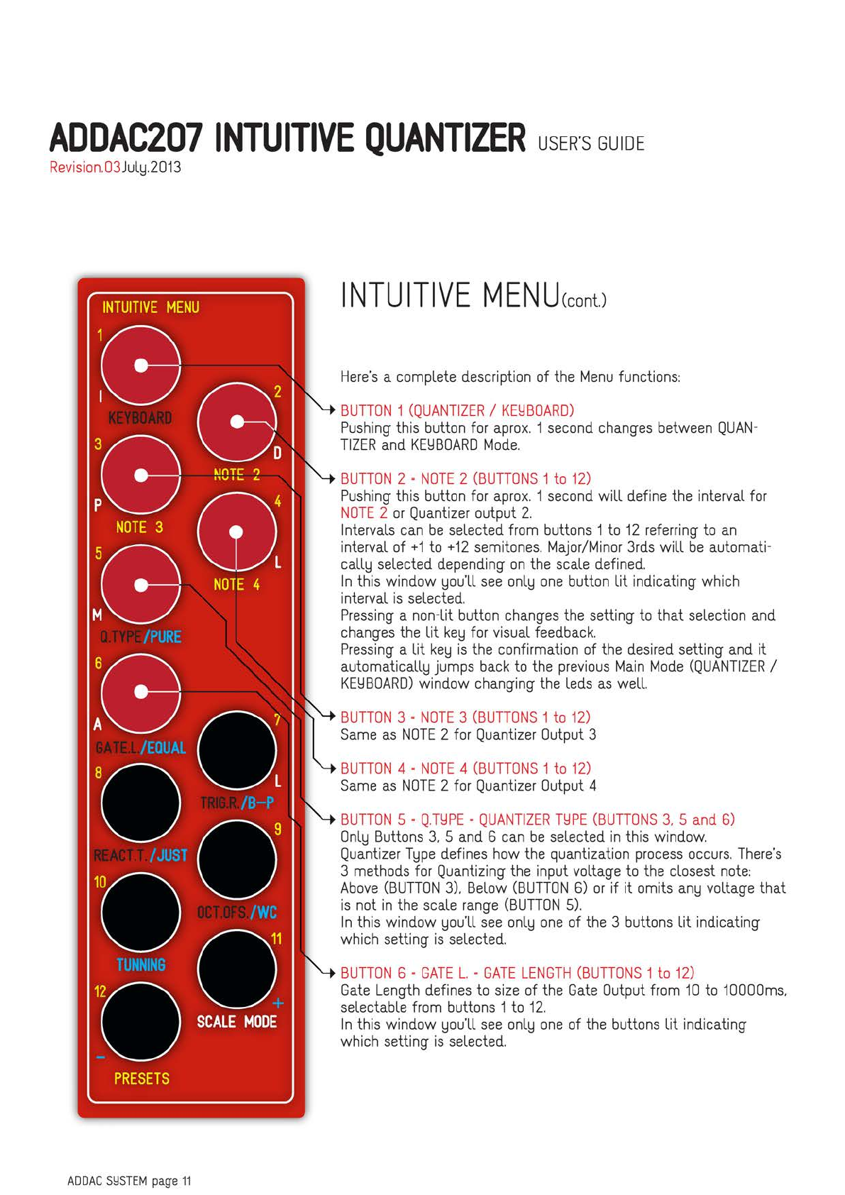
INTUITIVE
MEN
U(cont.)
Here's
a
complete
description
of
the
Menu
functions:
BUTTON
1
(QUANTIZER/
KELlBOARD)
Pushing
this
button
for
aprox.
1
second
changes
between
QUAN-
TIZER
and
KELlBOARD
Mode.
BUTTON
2 =
NOTE
2
(BUTTONS
1
to
12)
Pushing
this
button
for
aprox.
1
second
will
define
the
interval
for
NOTE
2
or
Quantizer
output
2.
Intervals
can
be
selected
from
buttons
1
to
12
referring
to
an
interval
of
+1
to
+12
semitones.
Major/Minor
3rds
will
be
automati-
calllJ
selected
depending
on
the
scale
defined.
In
this window
lJOu'll
see
onllJ
one
button
lit indicating
which
interval
is
selected.
Pressing
a non-lit
button
changes
the
setting
to
that
selection
and
changes
the
lit
kelJ
for
visual
feedback.
Pressing
a
lit
kelJ
is
the
confirmation
of
the
desired
setting
and
it
automaticalllJ jumps
back
to
the
previous
Main
Mode
(QUANTIZER
/
KELlBOARD)
window changing
the
leds
as
well.
BUTTON
3 =
NOTE
3
(BUTTONS
1
to
12)
Same
as
NOTE
2
for
Quantizer
Output
3
BUTTON
4 =
NOTE
4
(BUTTONS
1
to
12)
Same
as
NOTE
2
for
Quantizer
Output
4
BUTTON
5 =
Q.TLlPE
=
QUANTIZER
TLlPE
(BUTTONS
3,
5
and
6)
OnllJ
Buttons
3,
5
and
6
can
be
selected
in
this
window.
Quantizer
TlJpe
defines
how
the
quantization
process
occurs.
There's
3
methods
for
Quantizing
the
input voltage
to
the
closest
note:
Above
(BUTTON
3),
Below
(BUTTON
6)
or
if it
omits
anlJ
voltage that
is
not
in
the
scale
range
(BUTTON
5).
In
this window
lJOU'll
see
onllJ
one
of
the
3
buttons
lit indicating
which
setting
is
selected.
BUTTON
6 =
GATE
L.
=
GATE
LENGTH
(BUTTONS
1
to
12)
Gate
Length
defines
to
size
of
the
Gate
Output
from
10
to
10OOOms,
selectable
from
buttons
1
to
12.
In
this window
lJOU'll
see
onllJ
one
of
the
buttons
lit indicating
which
setting
is
selected.
ADDAC207
INTUITIVE
QUANTIZER
USER'S
GUIDE
Revision.O3
JullJ.2O13
ADDAC
Sl:ISTEM
page
12
INTUITIVE
MEN
U(cont.)
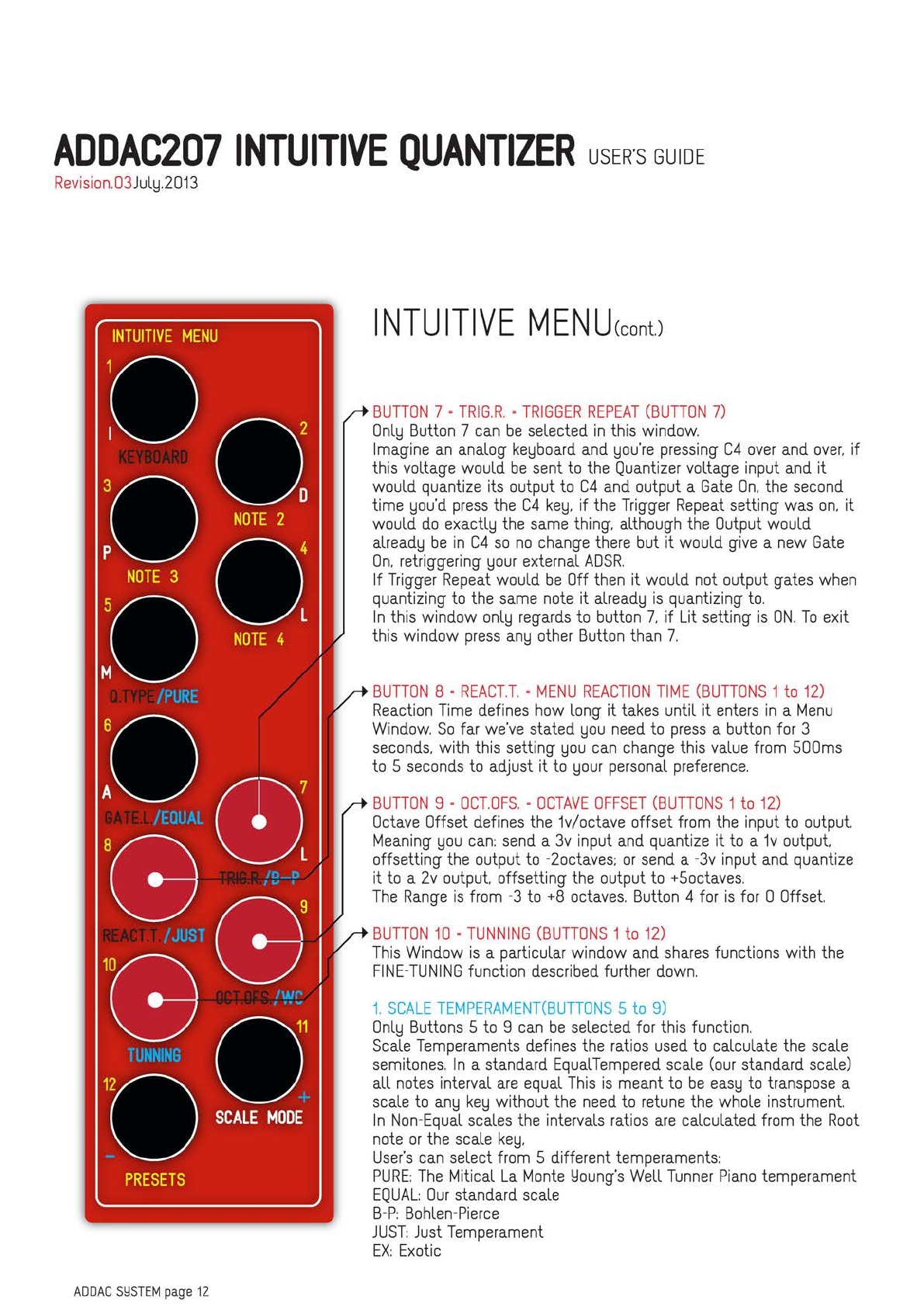
BUTTON
7 =
TRIG.R.
=
TRIGGER
REPEAT
(BUTTON
7)
OnllJ
Button
7
can
be
selected
in
this
window.
Imagine
an
analog
kelJboard
and
lJou·re
pressing
C4
over
and
over.
if
this
voltage would
be
sent
to
the
Quantizer
voltage input
and
it
would
quantize
its
output
to
C4
and
output a
Gate
On.
the
second
time
lJou'd
press
the
C4
kelJ,
if
the
Trigger
Repeat
setting
was
on,
it
would
do
exactllJ
the
same
thing. although
the
Output
would
alreadlJ
be
in
C4
so
no
change
there
but
it would
give
a
new
Gate
On.
retriggering
lJOUr
external
ADSR.
If
Trigger
Repeat
would
be
Off
then
it would
not
output
gates
when
quantizing
to
the
same
note
it
alreadlJ
is
quantizing
to.
In
this window
onllJ
regards
to
button
7,
if
Lit
setting
is
ON.
To
exit
this
window
press
anlJ
other
Button
than
7.
BUTTON
8 =
REACT.T.
=
MENU
REACTION
TIME
(BUTTONS
1
to
12)
Reaction
Time
defines
how
long it
takes
until it
enters
in
a
Menu
Window.
So
far
we've
stated
lJOU
need
to
press
a
button
for
3
seconds,
with
this
setting
lJOU
can
change
this
value
from
SOOms
to
5
seconds
to
adjust it
to
lJOUr
personal
preference.
BUTTON
9 =
OCT.OFS.
=
OCTAVE
OFFSET
(BUTTONS
1
to
12)
Octave
Offset
defines
the
1v/octave
offset
from
the
input
to
output.
Meaning
lJOU
can:
send
a
3v
input
and
quantize
it
to
a
1v
output
offsetting
the
output
to
-2octaves;
or
send
a
-3v
input
and
quantize
it
to
a
2v
output offsetting
the
output
to
+Soctaves.
The
Range
is
from
-3
to
+8
octaves.
Button
4
for
is
for
O
Offset.
BUTTON
10
=
TUNNING
(BUTTONS
1
to
12)
This
Window
is
a particular window
and
shares
functions with
the
FINE-TUNING
function
described
further
down.
1.
SCALE
TEMPERAMENT(BUTTONS
5
to
9)
OnllJ
Buttons
5
to
9
can
be
selected
for
this
function.
Scale
Temperaments
defines
the
ratios
used
to
calculate
the
scale
semitones.
In
a
standard
EqualTempered
scale
(our
standard
scale)
all
notes
interval
are
equal
This
is
meant
to
be
easlJ
to
transpose
a
scale
to
anlJ
kelJ
without
the
need
to
retune
the
whole
instrument.
In
Non-Equal
scales
the
intervals
ratios
are
calculated
from
the
Root
note
or
the
scale
kelJ.
User's
can
select
from
5 different
temperaments:
PURE:
The
Mitical
La
Monte
Lloung's
Well
Tunner
Piano
temperament
EQUAL:
Our
standard
scale
B-P:
Bohlen-Pierce
JUST:
Just
Temperament
EX:
Exotic
ADDAC207
INTUITIVE
QUANTIZER
USER'S
GUIDE
Revision.03
JullJ.2013
ADDAC
Sl:ISTEM
page
13
INTUITIVE
MEN
U(cont.)
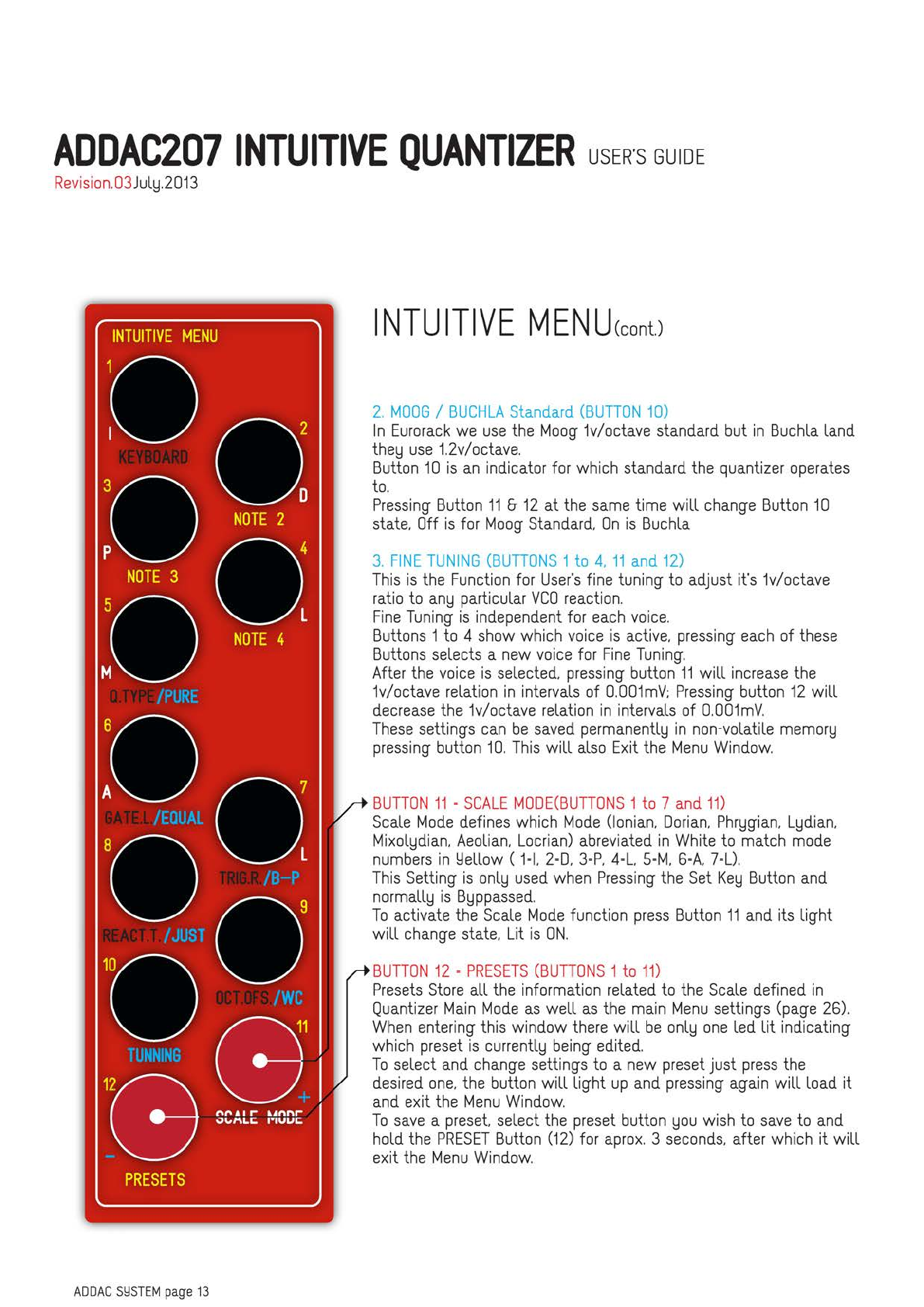
2.
MOOG
/
BUCHLA
Standard
(BUTTON
10)
In
Eurorack
we
use
the
Moog
1v/octave standard but
in
Buchla
land
thelJ
use
t2v/octave.
Button
10
is
an
indicator for which standard
the
quantizer
operates
to.
Pressing
Button
11
&
12
at
the
same
time
will
change
Button
10
state.
Off
is
for
Moog
Standard.
On
is
Buchla
3.
FINE
TUNING
(BUTTONS
1
to
4.
11
and
12)
This
is
the
Function
for
User's
fine tuning to adjust it's 1v/octave
ratio
to
anlJ
particular
VCO
reaction.
Fine
Tuning
is
independent for
each
voice.
Buttons 1
to
4
show
which
voice
is
active.
pressing
each
of
these
Buttons selects a
new
voice
for
Fine
Tuning.
After the
voice
is
selected.
pressing
button
11
will
increase
the
1v/octave relation
in
intervals of
0.001mV:
Pressing
button
12
will
decrease
the
1v/octave relation
in
intervals of
0.001mV.
These
settings
can
be
saved
permanentllJ
in
non-volatile
memorlJ
pressing
button
10.
This
will
also
Exit
the
Menu
Window.
BUTTON
11
=
SCALE
MODE(BUTTONS
1
to
7
and
11)
Scale
Mode
defines which
Mode
(Ionian.
Dorian.
PhrlJgian.
LlJdian.
MixollJdian.
Aeolian.
Locrian)
abreviated
in
White
to
match
mode
numbers
in
Llellow
(
1=1.
2=0.
3=P.
4=L.
S=M.
6=A.
7=U.
This
Setting
is
onllJ
used
when
Pressing
the
Set
KelJ
Button
and
normalllJ
is
BlJppassed.
To
activate
the
Scale
Mode
function
press
Button
11
and
its light
will
change
state. Lit
is
ON.
BUTTON
12
=
PRESETS
(BUTTONS
1
to
11)
Presets
Store
all
the
information related
to
the
Scale
defined
in
Quantizer
Main
Mode
as
well
as
the
main
Menu
settings
(page
26).
When
entering this window
there
will
be
onllJ
one
led
lit
indicating
which
preset
is
currentllJ
being
edited.
To
select
and
change
settings
to
a
new
preset
just
press
the
desired
one.
the button
will
light
up
and
pressing
again
will
load it
and
exit
the
Menu
Window.
To
save
a
preset.
select
the
preset
button
lJOU
wish
to
save
to
and
hold the
PRESET
Button
(12)
for
aprox.
3
seconds.
after which it
will
exit
the
Menu
Window.
ADDAC207
INTUITIVE
QUANTIZER
USER'S
GUIDE
Revision.O3
JullJ.2O13
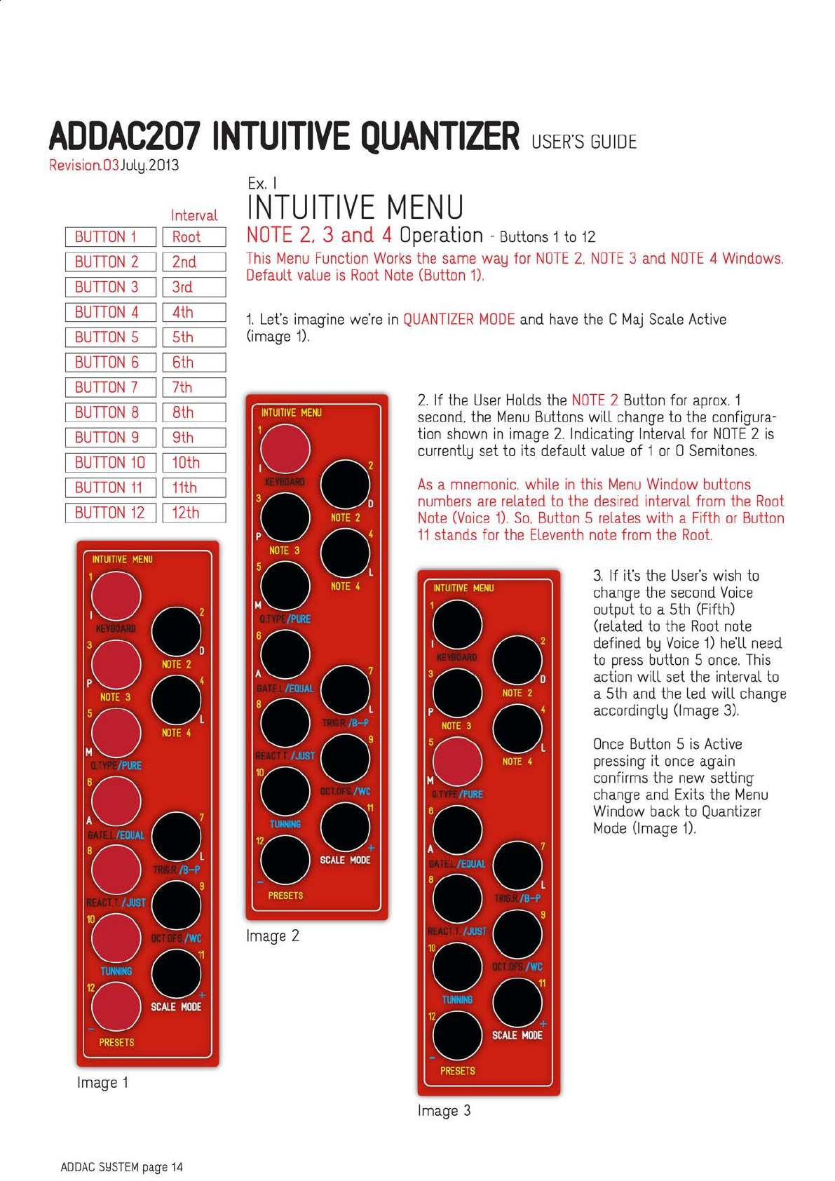
Interval
BUTTON
1
Root
BUTTON
2
2nd
BUTTON
3
3rd
BUTTON
4
4th
BUTTON
5
5th
BUTTON
6
6th
BUTTON
7
7th
BUTTON
8
8th
BUTTON
9
9th
BUTTON
10
10th
BUTTON
11
11th
BUTTON
12
12th
INTUITIVE
MENU
Oa
'O
NOTE2
O
p
NOTE3
o•
:o
NOTE<
I
:
00
7
•o I
'
00
'O
OCME~
1
PRESETS
Image
1
ADDAC
S!:ISTEM
page
14
Ex.
I
INTUITIVE
MENU
NOTE
2,
3
and
4
Operation
-
Buttons
1
to
12
This
Menu
Function
Works
the
same
walJ
for
NOTE
2.
NOTE
3
and
NOTE
4
Windows.
Default
value
is
Root
Note
(Button
1).
t
Let's
imagine
we're
in
QUANTIZER
MODE
and
have
the
C
Maj
Scale
Active
(image
1).
INTUITIVE
MENU
Oa
'O
NOTE2
O
p
NOTE3
o•
:o
NOTE<
I
:
00
7
•o I
,
oo
·
'O
-~
,
PRESETS
Image
2
2.
If
the
User
Holds
the
NOTE
2
Button
for
aprox.
1
second.
the
Menu
Buttons
will
change
to
the
configura-
tion
shown
in
image
2.
Indicating
Interval
for
NOTE
2
is
currentllJ
set
to
its
default
value
of
1
or
O
Semitones.
As
a
mnemonic.
while
in
this
Menu
Window
buttons
numbers
are
related
to
the
desired
interval
from
the
Root
Note
(Voice
1).
So.
Button
5
relates
with a
Fifth
or
Button
11
stands
for
the
Eleventh
note
from
the
Root.
INTUITIVE
MENU
Oa
'.
O
.m,
0
p
OOTE3
o•
:o
OOTE<
I
:
00
7
•o I
00
'O
~HO
~
PRESETS
Image
3
3.
If
it's
the
User's
wish
to
change
the
second
Voice
output
to
a
5th
(Fifth)
(related
to
the
Root
note
defined
blJ
Voice
1)
he'll
need
to
press
button
5
once.
This
action
will
set
the
interval
to
a
5th
and
the
led
will
change
accordingllJ
(Image
3).
Once
Button
5
is
Active
pressing
it
once
again
confirms
the
new
setting
change
and
Exits
the
Menu
Window
back
to
Quantizer
Mode
(Image
1).
ADDAC207
INTUITIVE
QUANTIZER
USER'S
GUIDE
Revision.O3
JullJ.2O13
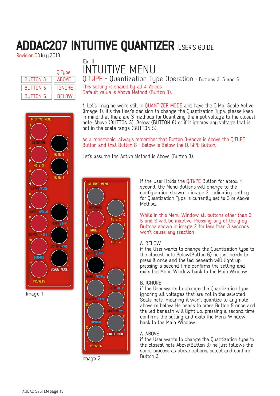
Q.TlJpe
BUTTON
3
11
ABOVE
BUTTON
5
11
IGNORE
I
BUTTON
6
11
BELOW
I
INTUITIVE
MENU
Oa
'0
NOTE2
°
p
N0TE3
o•
:o
NOTE<
I
:
00
7
•o I
'
00
'0
-,~
,
PRESETS
Image
1
ADDAC
Sl:ISTEM
page
15
Ex.
II
INTUITIVE
MENU
Q.T~PE
-
Quantization
T~pe
Operation
-
Buttons
3,
sand
6
This
setting
is
shared
blJ
all 4
Voices.
Default
value
is
Above
Method
(Button
3).
t
Let's
imagine
we're
still
in
QUANTIZER
MODE
and
have
the
C
Maj
Scale
Active
(image
1).
It's
the
User's
decision
to
change
the
Quantization
TlJpe.
please
keep
in
mind
that
there
are
3
methods
for
Quantizing
the
input voltage
to
the
closest
note:
Above
(BUTTON
3).
Below
(BUTTON
6)
or
if it
ignores
anlJ
voltage that
is
not
in
the
scale
range
(BUTTON
5).
As
a
mnemonic.
alwalJS
remember
that
Button
3-Above
is
Above
the
Q.TLlPE
Button
and
that
Button
6 -
Below
is
Below
the
Q.TLlPE
Button.
Let's
assume
the
Active
Method
is
Above
(Button
3).
INTUITIVE
MENU
Oa
3
0
NOTE2
D
p 0 4
NOTE
3
50 L
M
NOTE
4
:
00
7
•o I
'
00
"
'0
-~
,
PRESETS
Image
2
If
the
User
Holds
the
Q.TLlPE
Button
for
aprox.
1
second,
the
Menu
Buttons
will
change
to
the
configuration
shown
in
image
2.
Indicating setting
for
Quantization
T
lJpe
is
currentllJ
set
to
3
or
Above
Method.
While
in
this
Menu
Window
all
buttons
other
than
3,
5
and
6 will
be
inactive.
Pressing
anlJ
of
the
grelJ
Buttons
shown
in
image
2
for
less
than
3
seconds
won't
cause
anlJ
reaction
.
A.
BELOW
if
the
User
wants
to
change
the
Quantization
tlJpe
to
the
closest
note
Below(Button
6)
he
just
needs
to
press
it
once
and
the
led
beneath
will light
up.
pressing
a
second
time
confirms
the
setting
and
exits
the
Menu
Window
back
to
the
Main
Window.
B.
IGNORE
if
the
User
wants
to
change
the
Quantization
tlJpe
ignoring all voltages that
are
not
in
the
selected
Scale
note,
meaning
it won't
quantize
to
anlJ
note
above
or
below.
He
needs
to
press
Button
5
once
and
the
led
beneath
will light
up,
pressing
a
second
time
confirms
the
setting
and
exits
the
Menu
Window
back
to
the
Main
Window.
A.
ABOVE
if
the
User
wants
to
change
the
Quantization
tlJpe
to
the
closest
note
Above(Button
3)
he
just follows
the
same
process
as
above
options.
select
and
confirm
Button
3.

ADDAC207
INTUITIVE
QUANTIZER
USER'S
GUIDE
Revision.03
JullJ.2013
BUTTON
1
10
ms
BUTTON
2
20
ms
BUTTON
3
40
ms
BUTTON
4
80
ms
BUTTON
5
160
ms
BUTTON
6
320
ms
BUTTON
7
640
ms
BUTTON
8
1280
ms
BUTTON
9
2560
ms
BUTTON
10
5120
ms
BUTTON
11
10240
ms
GATE
LENGTH
INTUITIVE
MENU
Oa
'0
NOTE2
O
p
NOTE3
0'
:o
NOTE<
L
:
00
7
•o L
'
00
'
'
0-E~
,
PRESETS
Image
1
ADDAC
Sl:ISTEM
page
16
Ex.
Ill
INTUITIVE
MENU
GATE
L.
-
Gate
Length
Operation
-
Buttons
I
to
11
and
12
This
setting
is
shared
blJ
all 4
Voices.
Default
value
is
40
milliseconds
(Button
3).
The
Minimum
value
for
this
setting
is
10
milliseconds
(Button
1)
the
maximum
is
10240
miliseconds
(Button
II).
Time
intervals
increase
multipllJing
blJ
2.
meaning
the
next
button
is
twice
the
size
of
its
previous
one:
Button
1=10
Milliseconds:
2=20:
3=40:
4=80
...
and
so
on.
It
can
also
be
calculated with
the
formula:
Milliseconds
=10*r(ButtonX-1)
Button
12
is
used
for
a
GATE
OFF
CONDITION
before
Quantizing
a
new
note
(described
below).
So
let's
imagine
we
have
alreadlJ
pressed
the
GATE
L.
Button
for
aprox.
1
second
and
entered
in
its
Menu
Window.
the
Menu
Buttons
alreadlJ
changed
to
the
configu-
ration
shown
in
image
1.
displalJing
the
default setting
for
Gate
Length
or
Button
3.
INTUITIVE
MENU
Oa
'0
NOTE2
O
p
NOTE3
0'
:o
NOTE<
L
:
00
7
•o L
'
00
'
'
0-~
1
PRESETS
Image
2
If
it's
the
User's
wish
to
change
the
Gate
Length
to
anlJ
other
size
he'll
need
to
press
the
desired
length button
twice.
Let's
assume
Button
7 (640
miliseconds)
Once
Button
7
is
lit
(image
2)
pressing
it
once
again
confirms
the
new
setting
and
Exits
the
Menu
Window.
GATE
OFF
CONDITION
Button
12
acts
as
a
Toggle
(Lit=
On.
Unlit=
Off).
It limits
the
quantization
process
to
happen
onllJ
when
the
gate
Out
is
Off.
For
ex.
Imagine
the
User
had
alreadlJ
pressed
Button
12
(image
2)
setting
the
Gate
Length
to
be
10
seconds.
As
soon
as
the
module
quantizes
a
new
note
it will
set
the
Gate
Out
to
+5v
and
hold
it
there
for
the
pre-defined
time
of
10
seconds.
With
Button
12
Lit
(Condition
On)
it will
ignore
anlJ
input
and
will
not
quantize
anlJ
note
until
the
10
seconds
pass
and
the
Gate
set
to
Ov.

ADDAC207
INTUITIVE
QUANTIZER
USER'S
GUIDE
Revision.O3
JullJ.2O13
TRIG.R.
I
BUTTON
7
11
ON/OFF
I
INTUITIVE
MENU
Do
3
0
NOTE
2 D
p 0 4
NOTE
3
50 L
M
NOTE
4
:
00
7
'0 L
00
'
O-~:
PRESETS
Image
1
ADDAC
Sl:ISTEM
page
17
Ex.
IV
INTUITIVE
MENU
TRIG.
R.
-
Trigger
Repeat
Operation
-
Button
7
This
setting
is
shared
blJ
all 4
Voices.
Default
value
is
Off
So
let's
imagine
we
have
alreadlJ
pressed
the
TRIG.R.
Button
for
aprox.
1
second
and
entered
in
its
Menu
Window.
the
Button's
leds
change
but
no
led
is
lit
(image
1).
In
this
Menu
Window
onllJ
Button
7
can
be
lit
and
works
as
a
selector:
Unlit =
Off.
Lit
is
On.
INTUITIVE
MENU
Do
3
0
NOTE
2 D
p 0 4
NOTE
3
50 L
M
NOTE
4
:
00
7
'0 L
00
'0
~~-·:
PRESETS
Image
2
Pressing
Button
7
once
will activate
the
Trigger
Repeat
option
and
activate
the
according led
(image
2).
Saving
this setting
is
done
in
this
order.
select
the
state
lJOU
wish
to
save
pressing
Button
7
to
be
either
lit(On)
or
Unlit
(Off)
then
press
anlJ
kelJ
other
then
kelJ
7 (black
kelJs
in
image
2).
When
this
happens
the
User
confirms
the
kelJ
7
state
as
the
new
setting
and
returns
to
the
Main
Window.
ADDAC207
INTUITIVE
QUANTIZER
USER'S
GUIDE
Revision.03
JullJ.2013
INTUITIVE
MENU
Oa
'O
NOTE2
O
p
NOTE3
O'
:o
NOTE<
L
:
00
7
•o L
'
00
'
'
O-,~
'
PRESETS
Image
1
ADDAC
Sl:ISTEM
page
18
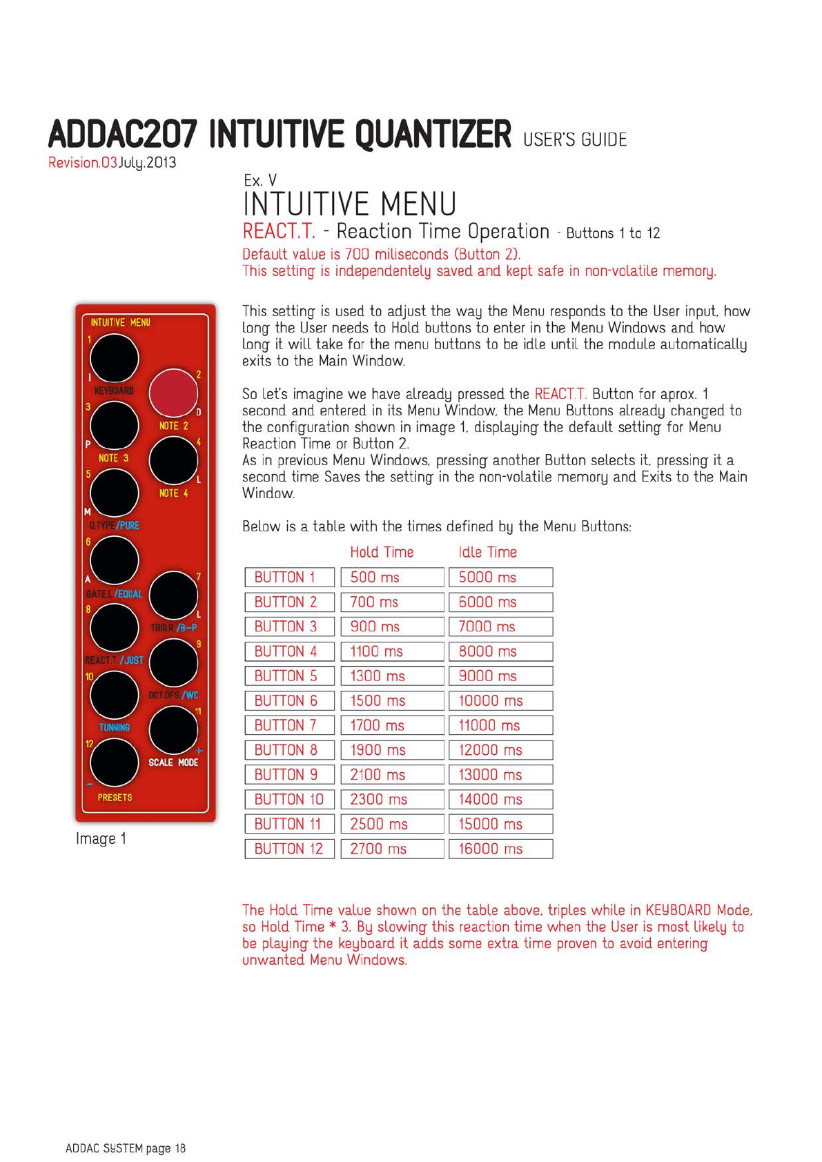
Ex.
V
INTUITIVE
MENU
REACT.T.
-
Reaction
Time
Operation
-
Buttons
1
to
12
Default
value
is
700
miliseconds
(Button
2).
This
setting
is
independentellJ
saved
and
kept
safe
in
non-volatile
memorlJ.
This
setting
is
used
to
adjust
the
walJ
the
Menu
responds
to
the
User
input
how
long
the
User
needs
to
Hold
buttons
to
enter
in
the
Menu
Windows
and
how
long it will
take
for
the
menu
buttons
to
be
idle
until
the
module
automaticallld
exits
to
the
Main
Window.
So
let's
imagine
we
have
alreadlJ
pressed
the
REACT.T.
Button
for
aprox.
1
second
and
entered
in
its
Menu
Window.
the
Menu
Buttons
alreadlJ
changed
to
the
configuration
shown
in
image
t
displalJing
the
default setting
for
Menu
Reaction
Time
or
Button
2.
As
in
previous
Menu
Windows.
pressing
another
Button
selects
it
pressing
it a
second
time
Saves
the
setting
in
the
non-volatile
memorlJ
and
Exits
to
the
Main
Window.
Below
is
a table with
the
times
defined
blJ
the
Menu
Buttons:
Hold
Time
Idle
Time
BUTTON
1
500
ms
5000
ms
BUTTON
2
700
ms
6000
ms
BUTTON
3
900
ms
7000
ms
BUTTON
4
1100
ms
8000
ms
BUTTON
5
1300
ms
9000
ms
BUTTON
6
1500
ms
10000
ms
BUTTON
7
1700
ms
11000
ms
BUTTON
8
1900
ms
12000
ms
BUTTON
9
2100
ms
13000
ms
BUTTON
10
2300
ms
14000
ms
BUTTON
11
2500
ms
15000
ms
BUTTON
12
2700
ms
16000
ms
The
Hold
Time
value
shown
on
the
table
above.
triples while
in
KELlBOARD
Mode.
so
Hold
Time
*
3.
BlJ
slowing
this
reaction
time
when
the
User
is
most
likellJ
to
be
plalJing
the
kelJboard
it
adds
some
extra
time
proven
to
avoid
entering
unwanted
Menu
Windows.

ADDAC207
INTUITIVE
QUANTIZER
USER'S
GUIDE
Revision.03
JullJ.2013
INTUITIVE
MENU
Oa
'0
NOTE2
°
p
NOTE3
0'
:o
NOTE<
L
:
00
7
•o L
'
00
'
'
0-E~
,
PRESETS
Image
1
ADDAC
Sl:ISTEM
page
19
Ex.
VI
INTUITIVE
MENU
OCT.OFS.
-
Octave
Offset
Operation
-
Buttons
1
to
10
This
setting
is
shared
blJ
all 4
Voices.
Default
value
is
O
Octaves
Offset
(Button
1).
The
Minimum
value
for
this
setting
is
O
Octaves
(Button
1)
and
the
maximum
is
+9
Octaves
(Button
10).
This
allows
for
negative
voltages
up
to
-Sv
to
be
quantized
as
well.
In
this
case
if
Oct.Ofs
setting
is
set to
5
octaves
-Sv
will
be
quantized
to
Ov.
-4v
to
1v
and
so
on.
If
Quantized
Notes
fall off
the
modules
voltage
range
thelJ
will
be
quantized
to
the
lowest
or
highest
note
possible.
So
let's
imagine
we
have
alreadlJ
pressed
the
OCT.OFS.
Button
for
aprox.
1
second
and
entered
in
its
Menu
Window,
the
Menu
Buttons
alreadlJ
changed
to
the
configu-
ration
shown
in
image
1.
displalJing
the
default setting
for
Octave
Offset
or
Button
1
(0
Octaves
Offset).
INTUITIVE
MENU
Oa
'O
NOTE2
°
p
NOTES
0'
:o
NOTE<
L
:
00
7
•o L
'
00
'
'O
-~
,
PRESETS
Image
2
If
it's
the
User's
wish
to
change
the
Octave
Offset
to
anlJ
other
value
he'll
need
to
press
the
desired
button
twice.
Let's
assume
Button
2
(1
octaves
Offset)
Once
Button
2
is
lit
(image
2)
pressing
it
once
again
confirms
the
new
setting
and
Exits
the
Menu
Window.
Here's
a
Table
With
the
Offset
values
for
each
Menu
Button:
BUTTON
1 0
Octaves
BUTTON
2 1
Octaves
BUTTON
3 2
Octaves
BUTTON
4 3
Octaves
BUTTON
5 4
Octaves
BUTTON
6 5
Octaves
BUTTON
7 6
Octaves
BUTTON
8 7
Octaves
BUTTON
9 8
Octaves
BUTTON
10
9
Octaves

ADDAC207
INTUITIVE
QUANTIZER
USER'S
GUIDE
Revision.O3
JullJ.2O13
INTUITIVE
MENU
Oa
'O
NOTE2
°
p
N0TE3
o•
:o
NOTE<
I
:
00
7
•o I
'
00
'O
-,~
,
PRESETS
Image
1
ADDAC
Sl:ISTEMpage
20
Ex.
VII
-
part
A
INTUITIVE
MENU
TUNING
Operations
-
Buttons
1
to
4
and
6
to
12
This
Menu
Window
has
4 different
functions:
Scale
Temperament
(Buttons
5
to
9)
Independent
Voice
Fine
Tuning
(Buttons
1
to
4.
11
and
12)
Moog/Buchla
Standard
Definition
(Buttons
11
and
12)
Saving
Fine
Tuning
Settings
(Button
10)
So
let's
imagine
we
have
alreadlJ
pressed
the
TUN
I
NG
Button
for
aprox.
1
second
and
entered
in
its
Menu
Window.
the
Menu
Buttons
alreadlJ
changed
to
the
configu-
ration
shown
in
image
1.
displalJing
both
the
default settings
for
Active
Voice
Tuning
(Button
1)
and
Scale
Temperament
(Button
6).
Active
Voice
Tuning
is
the
Quantizer
Voice
that
is
currentllJ
set
to
be
tuned.
Function
BUTTON
1
Tune
Voice
1
BUTTON
2
Tune
Voice
2
BUTTON
3
Tune
Voice
3
BUTTON
4
Tune
Voice
4
BUTTON
5 Well
Tunned
BUTTON
6
Equal
BUTTON
7
Bohlen-Pierce
BUTTON
8
Just
BUTTON
9
Exotic
BUTTON
10
Save
F.Tune
BUTTON
11
+
BUTTON
12


