Instruo eas User manual
eãs
Logic Module
User Manual


3
Description
Logic gates were originally used for the implementation of Boolean
functions in computation and in electronic devices. These functions were
performed on one or more binary inputs to create a single
binary output.
In music synthesis, this concept can be appropriated for many things
including the creation of interesting rhythmic patterns as well as patch-
based problem solving.
eãs is the be all and end all of logic modules. Sporting all of the classic
logic gate functions, it includes AND, NAND, OR, NOR, XOR, XNOR,
and NOT.
Everything from syncopated rhythmic structures, to CMOS-style ring
modulation, to creative solutions to your patch’s most glaring issues, eãs
is there.
Logic, after all, is the beginning of wisdom, not the end of it.
Features
• AND & NAND gate logic
• OR & NOR gate logic
• XOR & XNOR gate logic
• NOT gate logic

4
Installation
1. Confirm that the Eurorack synthesizer system is powered off.
2. Locate 4 HP of space in your Eurorack synthesizer case.
3. Connect the 10 pin side of the IDC power cable to the 2x5 pin
header on the back of the module, confirming that the red stripe on
the power cable is connected to -12V.
4. Connect the 16 pin side of the IDC power cable to the 2x8 pin
header on your Eurorack power supply, confirming that the red
stripe on the power cable is connected to -12V.
5. Mount the Instruō eãs in your Eurorack synthesizer case.
6. Power your Eurorack synthesizer system on.
Note:
This module has reverse polarity protection.
Inverted installation of the power cable will not damage the module.
Specifications
• Width: 4 HP
• Depth: 27mm
• +12V: 5mA
• -12V: 0mA
5
^^
~
^^
~
~
~
eãs
^^
~
^^
~
~
~
eãs
eãs | /es/ | noun (nature) a cascade of water falling from a height,
formed when a river or stream flows over a precipice or steep incline.
Key
1. AND Input 1
2. AND Input 2
3. AND Output
4. NAND Output
5. OR Input 1
6. OR Input 2
7. OR Output
8. NOR Output
9. XOR Input 1
10. XOR Input 2
11 . XOR Output
12. XNOR Ouput
13. NOT Input
14. NOT Output
1
3
5
7
9
2
4
6
8
10
13
11
14
12
Normalisation

6
Gate Logic
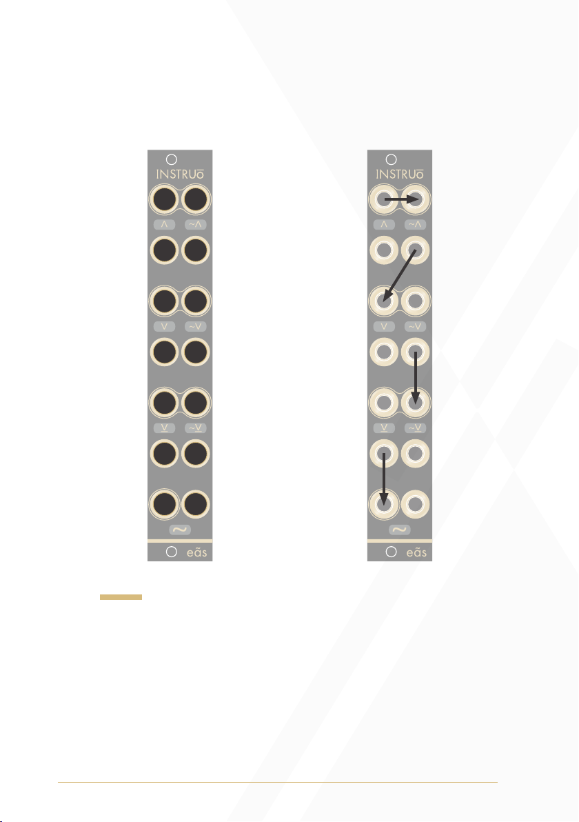
AND & NAND Gate Logic: In AND gate logic, voltage is held HIGH
at the output if all the inputs to the AND gate are held HIGH. If none or
not all inputs to the AND gate are HIGH, the output will be held LOW.
NAND gate logic is the inverse of AND gate logic.
• If the signal present at AND Input 1 and AND Input 2 are both held
HIGH, voltage will pass to the AND Output.
• The signal present at AND Input 1 normals to AND Input 2,
meaning that if there isn’t a cable connected to AND Input 2, the
AND gate will still function.
• An inverted copy of the AND gate is present at the NAND Output.
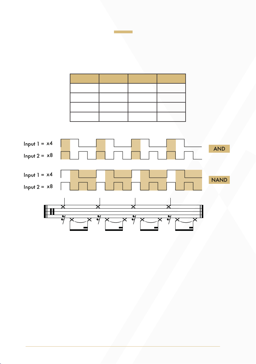
OR & NOR Gate Logic: In OR gate logic, voltage is held HIGH at the
output if one or both of the inputs to the OR gate are held HIGH. If
neither input is HIGH, the output will be held LOW. NOR gate logic is
the inverse of OR gate logic.
• If the signal present at either OR Input 1 or OR Input 2 is held
HIGH, voltage will pass to the OR Output.
• If using the OR gate only, a signal must be present at OR Input 1 for
OR Input 2 to function.
• An inverted copy of the OR gate is present at the NOR Output.
• The NAND Output normals to OR Input 1.
XOR and XNOR Gate Logic:
In XOR gate logic, voltage is held HIGH at the output if one, and only
one, of the inputs is held HIGH. If both inputs are held LOW or both are
held HIGH, the output will be held LOW. XNOR gate logic is the inverse
of XOR gate logic.

7
• If the signal is exclusively held HIGH at either XOR Input 1 or XOR
Input 2, but not both, voltage will pass to the XOR Output and
XNOR Output.
• An inverted copy of the XOR gate is present at the XNOR Output.
• The NOR Output normals to XOR Input 2.
NOT Gate Logic:
In NOT gate logic, voltage is held HIGH at the output if LOW voltage is
present at the input. Similarly, voltage is held LOW at the output if HIGH
voltage is present at the input.
• NOT gate logic is a way to invert gate and trigger signals.
• The XOR Output normals to the NOT Input.
8
Boolean Logic Tables
AND & NAND Gate Logic
0
0
1
1
1
1
1
0
0
1
0
1
0
0
0
1
Input 1 Input 2 AND NAND
9
OR & NOR Gate Logic
0
0
1
1
1
0
0
0
0
1
0
1
0
1
1
1
Input 1 Input 2OR NOR

10
XOR & XNOR Gate Logic
NOT Gate Logic
0
0
1
1
1
0
0
1
0
1
0
1
0
1
1
0
Input 1 Input 2XOR XNOR
0
1
1
0
Input NOT
11
Patch Examples
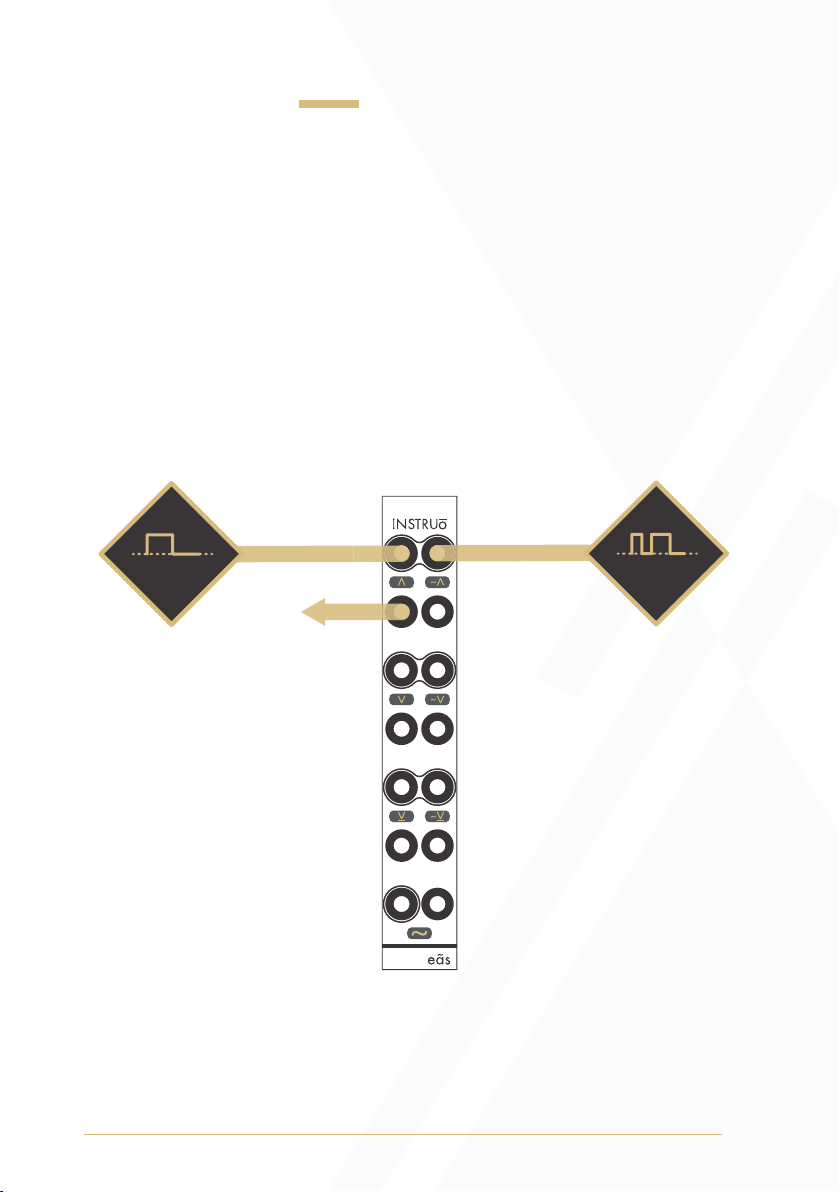
Pulse Syncing:
Summary: A primary use case for AND logic is to synchronize two
pulse signals. By connecting a steady clock signal to AND Input 1 and
connecting a faster random pulse signal to AND Input 2, the AND
Output will generate random pulses only when the steady clock signal is
held HIGH.
Output
Steady Clock Signal
Random Clock Signal
12
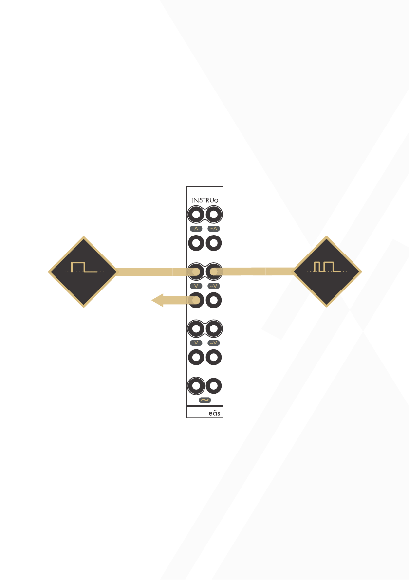
Pulse Mixing:
Summary: A primary use case for OR logic is to mix two pulse signals.
By connecting a pulse signal to OR Input 1 and a different pulse signal
to OR Input 2, the OR Output will generate a sum of the two pulse
signals, creating a more intricate pulse pattern.
Summed
Output
Clock Signal 1 Clock Signal 2

13
Rhythmic Variations:
Summary: Any two different clock signals or gate/trigger patterns can
be connected to one of the logic gates for interesting rhythmic outputs.
Experiment with different clock rates and logic gates. Take advantage
of the internal normalling and use three clock signals or gate/trigger
patterns instead of two.
Clock Signal 1
AND Output NAND Output
OR Output NOR Output
XOR Output XNOR Output
NOT Output
Clock Signal
3
Clock Signal 2
14
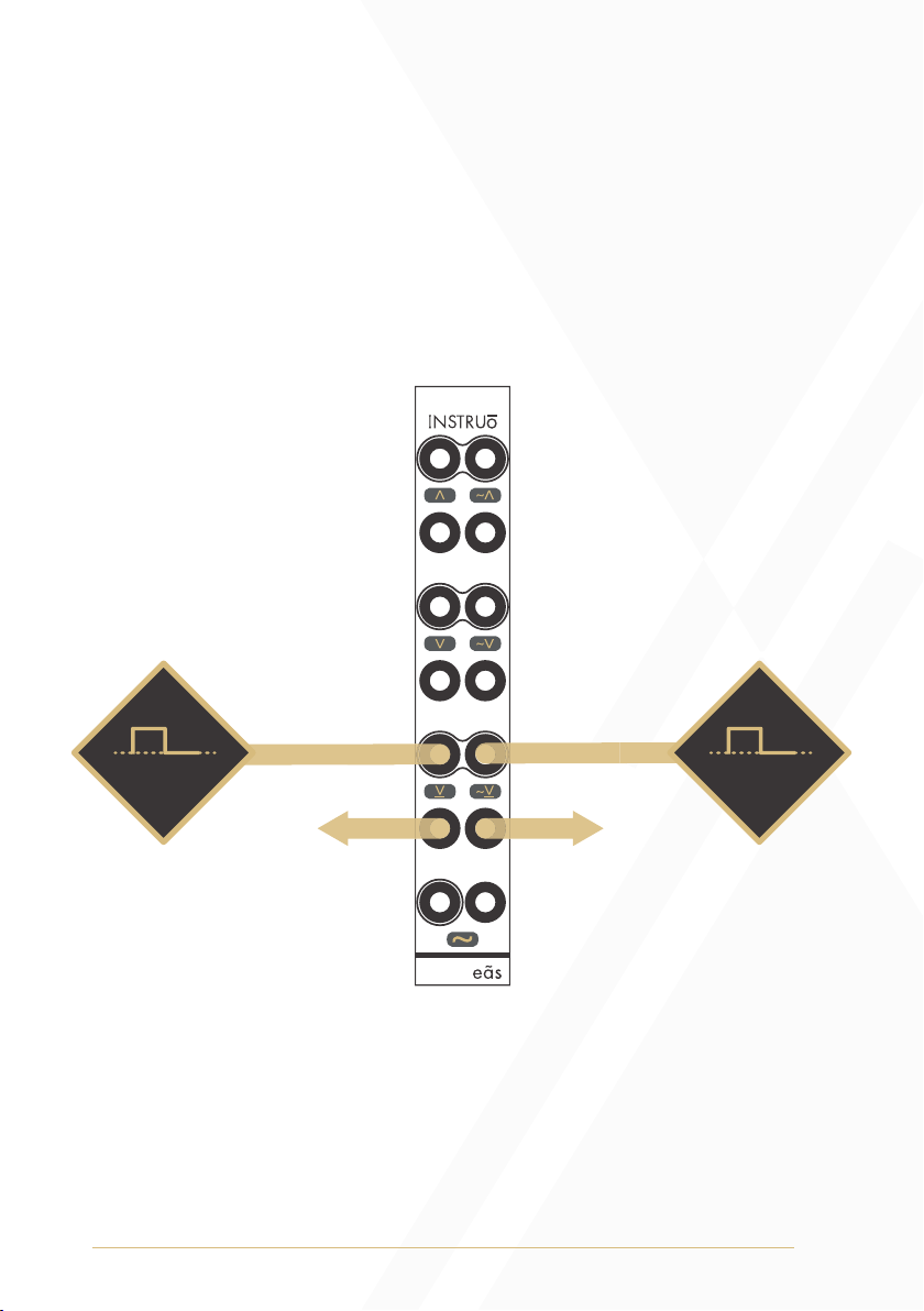
CMOS-Style Ring Modulation:
Summary: Connect two different audio signals to both XOR Inputs
for CMOS-style ring modulation effects. This style of ring modulation
is often used for synthesizing cymbal sounds. It’s also found on many
classic synthesizers as a way to add overtones to the primary
oscillator waveforms.
OutputOutput
Audio Rate
Signal 1
Audio Rate
Signal 2
15
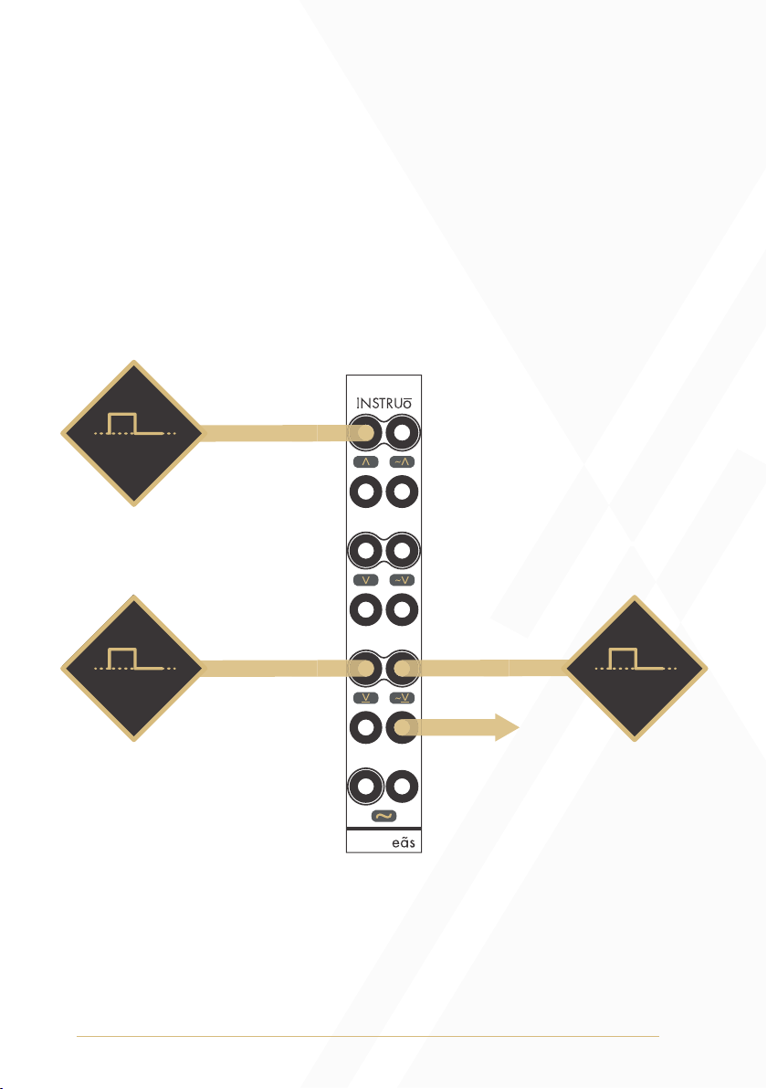
Cheapnis:
Summary: Combine audio rate signals at any of the logic gates for 1-bit
pulse code modulation tones. Unipolar positive audio rate signals will
result in authentically cheap digital sounds.
Output
Audio Rate
Signal 3
Audio Rate
Signal 2
Audio Rate
Signal 1

16
This device meets the requirements of the following standards: EN55032,
EN55103-2, EN61000-3-2, EN61000-3-3, EN62311.
Manual Author: Collin Russell
Manual Design: Dominic D’Sylva
Table of contents
Other Instruo Music Equipment manuals

Popular Music Equipment manuals by other brands

Technics
Technics ST-C700 operating instructions

ROCKMAN
ROCKMAN MIDI OCTOPUS operating manual

Inter-m
Inter-m AOE-212N Operation manual

Behringer
Behringer ULTRADRIVE PRO DCX2496 user manual

Leader Electronics Corp.
Leader Electronics Corp. LAG-120A instruction manual

Acoustic Signature
Acoustic Signature TA-700 instruction manual


