Yamaha SILENT SLG200S User manual

SERVICE MANUAL
HAMAMATSU, JAPAN
このサービスマニュアルは、2015年7月発行のSLG200S/
SLG200Nの増補版です。
点検・修理の際は、SLG200S/SLG200N(EG012145)の
サービスマニュアルを併せてご参照ください。
SLG200S
TBS
Tobacco Brown Sunburst
(タバコブラウンサンバースト)
SLG200N
NT
Natural
(ナチュラル)
SLG200N
TBS
Tobacco Brown Sunburst
(タバコブラウンサンバースト)
SLG200S
TBL
Translucent Black
(トランスルーセントブラック)
SLG200NW
NT
Natural
(ナチュラル)
SLG200N
TBL
Translucent Black
(トランスルーセントブラック)
SLG200S
NT
Natural
(ナチュラル)
SPECIFICATIONS(総合仕様)..................................................3
OUTER LAYOUT(外観図)........................................................4
CIRCUIT BOARD LAYOUT(ユニットレイアウト)...................6
DISASSEMBLY PROCEDURES(分解手順).............................7
CIRCUIT BOARD(シート基板図).......................................... 11
SETTINGMODELNUMBER(モデル番号設定方法).............13
INSPECTIONS(検査)............................................................14
PARTSLIST
BLOCK DIAGRAM(ブロックダイアグラム)
CIRCUITDIAGRAM(回路図)
CONTENTS(目次)
EG 012194
20111101-78750
Copyright (c) Yamaha Corporation. All rights reserved. PDF RN ’16.12
SLG200S/SLG200N
/SLG200NW
This is the enlarged edition of the service manual
for SLG200S/SLG200N series issued July 2015.
Use this manual for check or repair along with
the SLG200S/SLG200N series standard service
manual (EG 012145 ).

SLG200S/SLG200N/SLG200NW
2
IMPORTANT NOTICE
This manual has been provided for the use of authorized Yamaha Retailers and their service personnel. It has been assumed that basic
service procedures inherent to the industry, and more specifically Yamaha Products, are already known and understood by the users,
and have therefore not been restated.
WARNING : Failure to follow appropriate service and safety procedures when servicing this product may result in personal injury,
destruction of expensive components and failure of the product to perform as specified. For these reasons, we advise
all Yamaha product owners that all service required should be performed by an authorized Yamaha Retailer or the
appointed service representative.
IMPORTANT : This presentation or sale of this manual to any individual or firm does not constitute authorization certification,
recognition of any applicable technical capabilities, or establish a principal-agent relationship of any form.
The data provided is believed to be accurate and applicable to the unit(s) indicated on the cover. The research engineering, and service
departments of Yamaha are continually striving to improve Yamaha products. Modifications are, therefore, inevitable and changes in
specification are subject to change without notice or obligation to retrofit. Should any discrepancy appear to exist, please contact the
distributor’s Service Division.
WARNING : Static discharges can destroy expensive components. Discharge any static electricity your body may have accumulated
by grounding yourself to the ground bus in the unit (heavy gauge black wires connect to this bus.)
IMPORTANT : Turn the unit OFF during disassembly and parts replacement. Recheck all work before you apply power to the unit.
WARNING
Components having special characteristics are marked and must be replaced with parts having specification equal to those
originally installed.
CALIFORNIA PROPOSITION 65 WARNING: This product contains chemicals known to the State of California to cause cancer, or
birth defects or other reproductive harm.
DO NOT PLACE SOLDER, ELECTRICAL/ELECTRONIC OR PLASTIC COMPONENTS IN YOUR MOUTH FOR ANY REASON WHAT SO EVER!
Avoid prolonged, unprotected contact between solder and your skin! When soldering, do not inhale solder fumes or expose eyes to solder/ flux
vapor!
If you come in contact with solder or components located inside the enclosure of this product, wash your hands before handling food.

3
SLG200S/SLG200N/SLG200NW
SPECIFICATIONS(総合仕様)
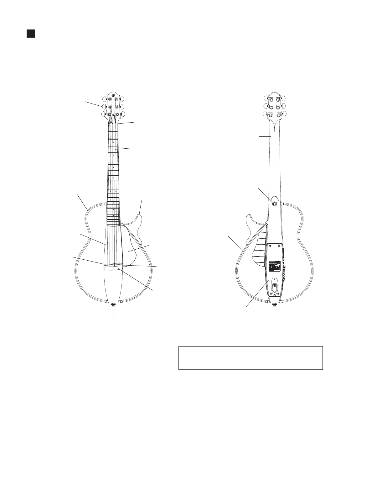
Neck / 棹Mahogany / マホガニー
Body / 胴Mahogany / マホガニー
Fingerboard / 指板 Rosewood / ローズウッド(SLG200S/SLG200N), Ebony / エボニー(SLG200NW)
Bridge / 下駒 Rosewood / ローズウッド
Frame / フレーム Rosewood / Maple / ローズウッド/メイプル
Strings / 弦SLG200S (Steel string model) : Folk guitar strings /
フォークギター用スチール弦(スティール弦モデル)
SLG200N/SLG200NW (Nylon string model) : Classic guitar nylon strings /
クラシックギター用ナイロン弦(ナイロン弦モデル)
Sensor / センサー Original piezo type bar sensor / ピエゾタイプオリジナルバーセンサー
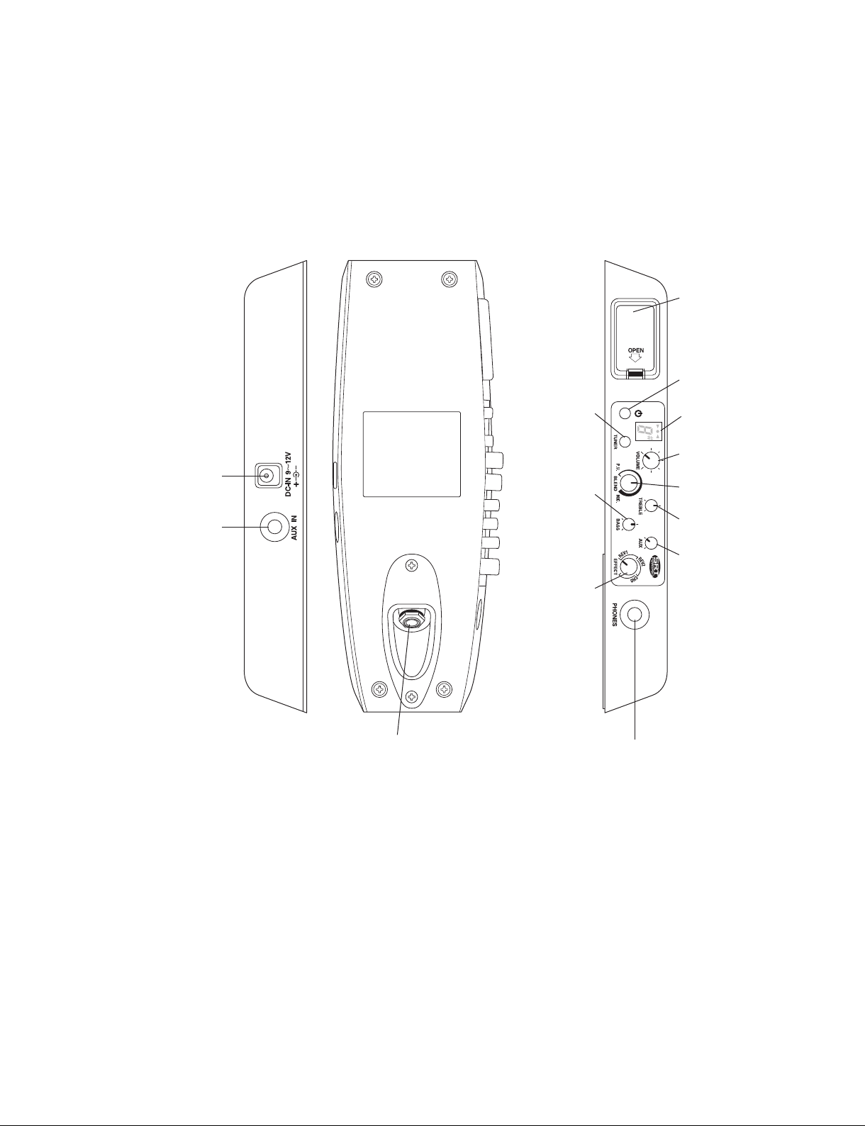
Controls / コントロール • Power Switch / 電源スイッチ • TUNER Switch / TUNERスイッチ
• VOLUME / ボリューム • TREBLE /トレブ ル
• BASS / バス • BLEND (P.U. ↔MIC.) / ブレンド(P.U.↔MIC)
• EFFECT (REV1 ↔REV2 ↔CHO) / エフェクト(REV1↔REV2↔CHO)
• AUX
Input/Output Jacks / 入出力ジャック • LINE OUT (Φ6.3 Standard Monaural / φ6.3モノラル標準
output impedance: 1 kΩ / 出力インピーダンス:1kΩ)
• PHONES (Φ3.5 Stereo mini / φ3.5ステレオミニ
output impedance: 10 Ω / 出力インピーダンス:10Ω)
• AUX IN (Φ3.5 Stereo mini / φ3.5ステレオミニ
input impedance: 2.2 Ω / 入力インピーダンス:2.2Ω)
• DC-IN
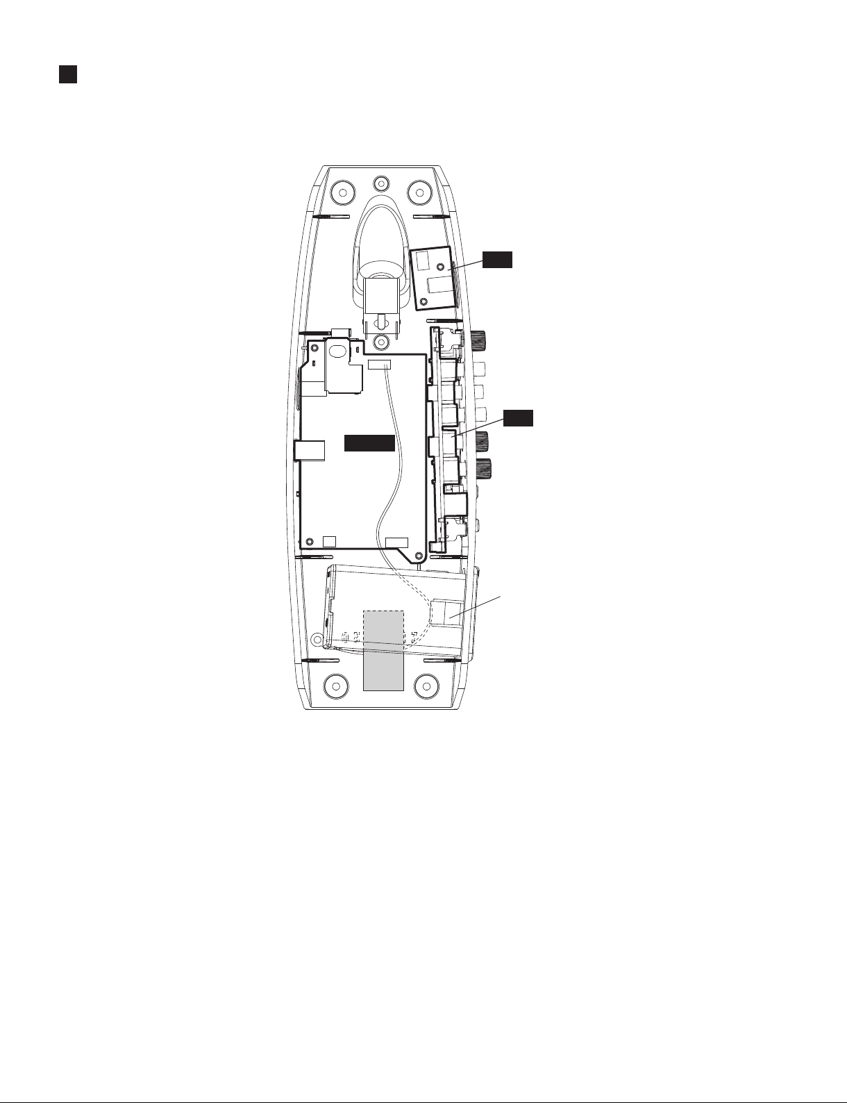
Power / 電源 Batteries: AA Alkaline (LR6) or NiMH Battery* x2
* Recommended NiMH battery: Eneloop by Panasonic.
* “Eneloop” is a registered trademark of the Panasonic Group.
Power Adaptor (sold separately):Yamaha PA-3C (for use in Japan), PA-130
(for use internationally), DC 12 V/700 mA
電池:単三形アルカリ乾電池(LR6)またはニッケル水素電池*×2本
*推奨ニッケル水素電池:パナソニックグループ製eneloop(エネループ)
*「eneloop」はパナソニックグループの登録商標です。
電源アダプター(別売):YamahaPA-3C(日本でご使用の場合)、PA-130(海外でご使用の場
合)、DC12V/700mA
Power Consumption / 消費電力 2 W (with the PA-3C), 0.8 W (with the PA-130), 0.9 W (with the PA-130A, B) /
2W(PA-3C 使用時)、0.8W(PA130 使用時)、0.9W(PA130A、B 使用時)
Battery Life (Continuous use) /
電池寿命(連続使用時)
• Alkaline Batteries: Approximately 22 hours / アルカリ乾電池:約22時間
• NiMH Batteries: Approximately 18 hours (eneloop 1900 mAh) /
ニッケル水素電池:約18時間(eneloop1900mAhモデル)
String Length / 弦長 SLG200S (Steel string model) : 634 mm (24-15/16”) / 634mm(スティール弦モデル)
SLG200N/SLG200NW (Nylon string model) :
650 mm (25-9/16”) / 650mm(ナイロン弦モデル)
Dimensions / 寸法
SLG200S (Steel string model) : 978 (L) x 356 (W) x 85 (H) mm (38-1/2” x 14” x 3-3/8”)
SLG200N/SLG200NW (Nylon string model) :
970 (L) x 356 (W) x 87 (H) mm (38-3/16” x 14” x 3-7/16”)
* with the detachable frame attached, and includes the frame fixing screws.
978(L)×356(W)×85(H)mm(SLG200S/スティール弦モデル)
970(L)×356(W)×87(H)mm(SLG200N/ナイロン弦モデル)
*着脱式フレーム取付、フレー ム 固 定ネジ 含む
Weight / 質量 approximately 2.1 kg (4 lbs. 10 oz.) / 約2.1kg

SLG200S/SLG200N/SLG200NW
4
OUTER LAYOUT(外観図)
TUNING PEG
(糸巻(ペグ))
s&RONT(フロント) s2EAR(リア )
NUT
(上駒(ナット))
NECK
(棹(ネック))
FINGERBOARD
(指板(フィンガーボード))
HORN (LEG SUPPORT)
(ホーン(膝当て))
FINGER REST
(フィンガーレスト)
PICKUP
(UNDERNEATH THE SADDLE)
(ピックアップ(サドルの下部))
BRIDGE
(下駒(ブリッジ))
FRAME FIXING SCREW 2
(DOUBLES AS THE STRAP PIN)
(フレーム固定ネジ2(ストラップピン兼用))
FRAME FIXING SCREW 1
(DOUBLES AS THE STRAP PIN)
(フレーム固定ネジ1(ストラップピン兼用))
BODY
(胴(ボディ))
SADDLE
(サドル)
LEFT FRAME (REMOVABLE)
(左フレーム(脱着可))
RIGHT FRAME (FIXED)
(右フレーム(固定式))
REAR ELECTRONICS SECTION (See Page 5.)
(リア電装部(5ページ参照))
The steel string model is used in the illustration above. (Tuning pegs, fingerboard,
and bridge shape are different on the nylon string model.)
イラストはスティール 弦 モデ ルです 。(ナイロン弦モデルとは糸巻き、指板、下駒等の形状が
異なります 。)

5
SLG200S/SLG200N/SLG200NW
s#ONTROL0ANEL(電装パネル部)
Battery Case
(電池ケース)
Power Switch
(電源スイッチ )
Display
(ディスプレイ)
TUNER Switch
(チューナースイッチ )
VOLUME Control
(ボリュームコントロール )
BLEND Control
(ブレンドコントロール )
TREBLE Control
(トレブ ル コントロール )
BASS Control
(バスコントロール )
EFFECT Control
(エフェクトコントロール )
AUX Control
(AUXコントロール )
PHONES Jack(Stereo Mini)
(ヘッドフォンジャック(ステレオミニ))
LINE OUT Jack (Monaural)
(LINEOUTジャック(モノラル標準))
AUX IN Jack
(Stereo Mini)
(AUXINジャック
(ステレオミニ))
Power AdaptorJack
(電源アダプタージャック)

SLG200S/SLG200N/SLG200NW
6
CIRCUIT BOARD LAYOUT(ユニットレイアウト)
PH
PN
MAIN
BATTERY BOX
(電池 BOX)

7
SLG200S/SLG200N/SLG200NW
DISASSEMBLY PROCEDURE(分解手順)
Preparations
Make the following preparations;
•Remove the battery case and battery.
Fig. 1
(図1)
1. Frame A (Time required: About 1 minute)
1-1 Loosen the two (2) strap pins marked [D15]. The frame
A can then be removed. (Fig. 1)
3. Frame B (Time required: About 1 minute)
3-1 Remove the four (4) screws marked [D13]. The frame
B can then be removed together with the horn. (Fig. 1)
4. Horn, Bracket B
(Time required: About 1 minute each)
4-1 Remove the frame B. (See procedure 3.)
4-2 Horn :
Remove the three (3) screws marked [D12]. The horn
can then be removed . (Fig. 1)
4-3 Bracket B :
Remove the two (2) screws marked [D05]. The upper
bracket B1 can then be removed . (Fig. 1)
The lower bracket B2 can be removed in the same manner.
2. Bracket A (Time required: About 1 minute)
2-1 Remove the frame A. (See procedure 1.)
2-2 Remove the two (2) screws marked [G07]. The upper
bracket A1 can then be removed from the frame A.
(Fig. 1)
The lower bracket A2 can be removed in the same manner.
[D15]
[G07]
[G07]
[D13] [D05]
[D13]
[D05]
[D12]
[D15]
FRAME A
(フレームA)
FRAME B
(フレームB)
HORN
(ホーン)
BRACKET A1
(ブラケットA1)
BRACKET B1
(ブラケットB1)
BRACKET A2
(ブラケットA2)
BRACKET B2
(ブラケットB2)
準備
作業を行う前に下記のことを行ってください。
•電池ケースを外し、乾電池を取り外します。
1. フレームA
(所要時間:約1分)
1-1 [D15]のストラップピン2本を緩めて、フレームA
を外します。(図1)
3. フレームB
(所要時間:約2分)
3-1 [D13]のネジ4本を外して、ホーンと共にフレーム
Bを外します。(図1)
4. ホーン、ブラケットB
(所要時間:各約2分)
4-1 フレームBを外します。(3項参照)
4-2 ホーン:
[D12]のネジ3本を外して、ホーンを外します。(図1)
4-3 ブラケットB:
[D05]のネジ2本を外して、上側のブラケットB1を
外します。(図1)
下側のブラケットB2も、同様にして外すことができ
ます。
2. ブラケットA
(所要時間:約1分)
2-1 フレームAを外します。(1項参照)
2-2 [G07]のネジ2本を外して、フレームAから上側の
ブラケットA1を外します。(図1)
下側のブラケットA2も、同様にして外すことがで
きます。
※This figure shows the SLG200N.
(この図は、SLG200Nです。)

8
SLG200S/SLG200N/SLG200NW
5. Control Panel
(Time required: About 1 minutes)
5-1 Remove the four (4) screws marked [J10]. The control
Panel black can then be removed. (Fig. 2)
6. MAIN Circuit Board
(Time required: About 2 minutes)
6-1 Remove the control panel black. (See procedure 5.)
6-2 Disconnect allconnectors on the MAIN circuit board.
(Fig. 3, Photo. 1)
6-3 Remove the three (3) screws marked [13a]. The MAIN
circuit board can then be removed. (Fig. 3, Photo. 1)
Fig. 2
(図2)
Photo. 1
(写真1)
>D@
>D@
MAIN CIRCUIT BOARD
(MAINシート)
5. 電装パネル
(所要時間:約1分)
5-1 [J10]のネジ4本を外して、電装パネルを外します。
(図2)
6. MAINシート
(所要時間:約2分)
6-1 電装パネルを外します。(5項参照)
6-2 MAINシートに接続されているコネクタを全て外
します。(図3、写真1)
6-3 [13a]のネジ3本を外して、MAINシートを外します。
(図3、写真1)
>-@ >-@

9
SLG200S/SLG200N/SLG200NW
7. PH Circuit Board
(Time required: About 1 minutes)
7-1 Remove the control panel black. (See procedure 5.)
7-2 Remove the two (2) screws marked [13b]. The PH
circuit board can then be removed. (Fig. 3)
8. PN Circuit Board
(Time required: About 7 minutes)
8-1 Remove the control panel black. (See procedure 5.)
8-2 Remove the MAIN circuit board. (See procedure 6.)
8-3 Pull out the three (3) voiume knobs for [VOLUME],
[BLEND], [EFFECT]. (Fig. 4)
8-4Cover a thin flat-chip screwdriver with a cloth. Press the
clearance of the LED display area with the screwdriver
to make clearance between the control panel black and
the plate/panel printing. Then remove the print panel
from the clearance. The removed plate/panel printing
will no longer be used. (Fig. 4,Photo 2,3)
8-5Remove the four (4) dish head tapping screws marked
[11]. The PN circuit board can then be removed. (Fig. 3)
Fig. 3
(図3)
[13a]
[11]
[12]
CONTROL PANEL BLACK
(電装パネル)
JACK PLATE
(ジャックプレート)
[13b]
MAIN
PN
PH
Power Switch
(電源スイッチ )
TUNER Switch
(チューナースイッチ )
VOLUME
(ボリューム )
BLEND
(ブレンド)
EFFECT
(エフェクト)
PLATE/PANEL PRINTING
(印刷パネル)
CONNECTOR (CN307)
(コネクタ(CN307))
7. PHシート
(所要時間:約1分)
7-1 電装パネルを外します。(5項参照)
7-2 [13b]のネジ2本を外して、PHシートを外します。
(図3)
8. PNシート
(所要時間:約7分)
8-1 電装パネルを外します。(5項参照)
8-2 MAINシートを外します。(6項参照)
8-3 [VOLUME]、[BLEND]、[EFFECT]のボリューム
ノブ3個を引き抜きます。(図4)
8-4 細いマイナスドライバーを布で覆い、LED表示部
隙間から押して、電装パネル本体と印刷パネルに
隙間を作り、そこから剥がしていきます。剥がし
た印刷パネルは再利用しません。(図4、写真2、3)
8-5 [11]の精密ネジ4本を外して、PNシートを外しま
す。(図3)

10
SLG200S/SLG200N/SLG200NW
Fig. 5
(図5)
Fig. 4
(図4)
>-@
9. Jack Plate (Time required: About 1 minutes)
9-1 Remove the control panel black. (See procedure 5.)
9-2 Remove the connector (CN307) attached to the MAIN
circuit board. (Fig. 3)
9-3 Remove the round head wood screw marked [J07]
attached to the body. (Fig. 5)
9-4 Remove the two (2) screws marked [12]. The jack plate
can then be removed. (Fig. 3)
9. ジャックプレート
(所要時間:約1分)
9-1 電装パネルを外します。(5項参照)
9-2 MAINシートに接続されているコネクタ(CN307)
を外します。(図3)
9-3 胴に取り付けられている[J07]の鍋木ネジを外し
ます。(図5)
9-4 [12]のネジ2本を外して、ジャックプレートを外し
ます。(図3)
Photo. 2
(写真2) Photo. 3
(写真3)
CONTROL PANEL BLACK
(電装パネル)
FLAT-CHIP SCREWDRIVER
(細いマイナスドライバー)
PLATE/PANEL PRINTING *LED display area
(印刷パネル※LED表示部)
CONTROL PANEL BLACK
(電装パネル)
FLAT-CHIP SCREWDRIVER
(細いマイナスドライバー)
PLATE/PANEL PRINTING *LED display area
(印刷パネル※LED表示部)
FLAT-CHIP SCREWDRIVER
(細いマイナスドライバー)
PLUG IT INTO THE CLEARANCE
(隙間に差し込みます)
PLATE/PANEL PRINTING *LED display area
(印刷パネル※LED表示部)
CONTROL PANEL BLACK
(電装パネル)
PN

11
SLG200S/SLG200N/SLG200NW
MAIN Circuit Board (ZK016103) .............................................................. 11
PN Circuit Board (ZK016107) ................................................................... 12
PH Circuit Board (ZK016105) ................................................................... 12
CIRCUIT BOARDS(シート基板図)
Note: See parts list for details of circuit board component parts.
注 : シートの部品詳細は、パーツリストをご参照ください。
●MAIN Circuit Board
C2NA0-2001134138 2
Pattern side(パターン側)
Component side(部品側)
to PH-CN901
to PN-CN704
to PN-CN702
N.C.
to PN-CN703 AUX IN
(L/R)
DC-IN 9~12V
to LINE OUT Jack
to PU IN
to BATTERY IN

13
SLG200S/SLG200N/SLG200NW
SETTING MODEL NUMBER(モデル番号設定方法)
•The model number must be set when the Flash ROM and DM sheets are replaced.
•FlashROM、DMシートを交換した場合は、モデル番号を設定する必要があります。
1.準備
(1)操作子が以下の設定になっている事を確認しま
す。異なっている場合は合わせます。
•POWER :OFF
•VOLUME:最小
•BLEND :最小
•TREBLE :中心(センタークリック位置)
•BASS:中心(センタークリック位置)
•AUX :最小
•EFFECT :最小
2.モデル設定手順
(1)TUNERスイッチを押したまま電源ONにします。
(2)TUNERスイッチを離さず、BLENDつまみを右
→左の順に回します。
(3)TUNERスイッチを離します。
(4)モデル選択処理に入りLEDに"0"または"1"、"2"
の設定モデル番号が表示されるので、BLENDつ
まみを操作します。
•左に回しきると"0"が表示されます。
•中央付近に回すと"1"が表示されます。
•右に回しきると"2"が表示されます。
(5)番号を選択しTUNERスイッチを押して決定し、
Playモード(通常モード)に移行します。
(6)POWERスイッチを長押しして電源OFFにします。
3.モデル確認手順
(1)TUNERスイッチを押したまま電源ONにします。
(2)TUNERスイッチを離さず、BLENDつまみを右
→左の順に回します。
(3)TUNERスイッチを離し、モデル番号を確認しま
す。モデル名と番号の対応は下記表を参照します。
(4)確認が終わったらTUNERスイッチを押します。
(5)POWERスイッチを長押しして電源OFFにします。
Modelname(モデル名) Number(番号)
SLG200S 0
SLG200N 1
SLG200NW 2
1. Preparation
(1) Checkthateachoperatorisonthefollowing
setting.Ifitisnot,adjustthesetting.
•POWER: OFF
•VOLUME: MIN
•BLEND: MIN
•TREBLE: Center (Center click position)
•BASS: Center (Center click position)
•AUX: MIN
•EFFECT: MIN
2. Steps of model configuration
(1) Turn on the power while pushing down the TUNER
switch.
(2) Without letting go of the TUNER switch, turn the BLEND
knob right, then left.
(3) Let go of the TUNER switch.
(4) Enter the model selection process and when “0”or “1”, “2”
Setting model number is displayed on the LED, turn the
BLEND knob.
• Turn all the way to the left and “0” will be displayed.
• Turn the way to the Near the center and “1” will be
displayed.
• Turn all the way to the right and “2” will be displayed.
(5) Select a number, confirm it by pressing the TUNER
switch, and transition to play mode (normal mode).
(6) Press and hold the POWER switch to turn off the power.
3. Steps of model confirmation
(1) Turn on the power while pushing down the TUNER
switch.
(2) Without letting go of the TUNER switch, turn the BLEND
knob right, then left.
(3) Let go of the TUNER switch, and check the model
number. Reference the chart below for compatibility of
the model name and number.
(4) After confirmation, press the TUNER switch.
(5) Press and hold the POWER switch to turn off the power.

14
SLG200S/SLG200N/SLG200NW
INSPECTIONS(検査)
1. 治具
•パワードスピーカー
•高感度交流電圧計(レベルメータ)
•オシロスコープ
•イヤホン•チューナー
•オーディオプレーヤー
•乾電池×2本 •ACアダプター(PA-130B)
2. 準備
下図のように接続します。
3. モデル番号及びプログラムバージョン番号の確認
(1)TUNERスイッチを押しながら電源スイッチを
押し、LEDが点灯したらTUNERスイッチを
離します。
表示されるモデル番号及びプログラムバージョン
番号を確認します。
(例)SLG200S :120
−
0
−
3d
SLG200N :120
−
1
−
3d
SLG200NW:120
−
2
−
3d
•本体に乾電池を入れます。
•一度電源スイッチを押し、電源をOFFにします。
• 特に指示がない場合、各つまみの設定を次のよう
にします。
「VOLUME」 =最大
「BLEND」 =最小(PU側)
「BASS」・「TREBLE」 =中央
「EFFECT」 =最小(REV1側)
「AUX」 =最大
1. Required Equipment
•Powered Speaker
•High-sensitivity AC voltmeter (level meter)
•Oscilloscope
•Earphone
•Audio Player •Tuner
•Battery x2 •AC adapter (PA-130B)
2. Preparation
Perform connection as shown in the figure below.
3. Confirmation of Model number and Program
version number
(1) While pressing the TUNER switch, press the power
switch. When LED illuminates, release the TUNER
switch.
Confirm the model number and the program version
number displayed.
(Ex.) SLG200S : 1_20
−
0
−
3d
SLG200
N
: 1_20
−
1
−
3d
SLG200
NW
: 1_20
−
2
−
3d
•Put the batteries in the body.
•Once press the power switch, and then turn OFF the power.
•Unless otherwise specified, the controls should be set as
follows.
[VOLUME] =MAX
[BLEND] =MIN (PU SIDE)
[BASS] • [TREBLE] =CENTER
[EFFECT] =MIN (REV1 SIDE)
[AUX] =MAX
($53+21(6
(イヤホン)
32:(5('63($.(5
(パワードスピーカー)
$&92/70(7(5
(交流電圧計)
26&,//26&23(
(オシロスコープ)
$&$'$37(5
(ACアダプター)
$8',23/$<(5
(オーディオプレーヤー)
67(5(20,1,&$%/(P
(ステレオミニケーブル(1m))
①6+,(/'('&$%/(P%1&&211(&725φ02125$/
3+21(3/8*
(シールドケーブル(1m)BNCコネクタ/φ6.3標 準 モノラルフォンプラグ)
③%1&$'$37(5
(BNCアダプター)
④%1&$'$37(5
(BNCアダプター)
②6+,(/'('&$%/(P%1&&211(&725[
(シールドケーブル(1m)BNCコネクタ×2)
①
③
④
②
プログラム
バージョン
program
version
model
number Checksum
チェックサムモデル番号

15
SLG200S/SLG200N/SLG200NW
4. 音量・弦間音量バランス・音質の確認
(正規調律してから、確認してください。)
(1)各つまみの設定を次のようにします。
「VOLUME」 =最大
「BLEND」 =最小(PU側)
「BASS」・「TREBLE」 =中央
「EFFECT」 =最小(REV1側)
「AUX」 =最小
(2)1弦から6弦迄、均一な力で、各弦3 〜 4回ほどダ
ウン・アップピッキングを繰り返しながら弾きます。
(3)正常な音量がLINE OUTから出ていることを確認
します。
(4)弦間の音量差に違和感のないことを確認します。
(1弦から6弦までのバラツキは約6dB以内)
(5)ダウンピッキングのときとアップピッキングのと
きで、音量差に違和感のないことを確認します。
(6dB以内)
(6)ダウンピッキングのときとアップピッキングのと
きで、音色に違いがないことを確認します。
5. 異音検査
(正規調律してから、確認してください。)
(1)弦(指板と下駒の間)を手で1〜6弦同時に叩いて
も、ケーブルのビリツキなどの異音がしないこと
を確認します。
(2)本体を軽く揺らしても、ケーブルのビリツキなど
の異音がしないことを確認します。
6. マイクシミュレータ音質の確認
(正規調律してから、確認してください。)
(1)各つまみの設定を次のようにします。
「VOLUME」 =最大
「BASS」・「TREBLE」 =中央
「EFFECT」 =最小(REV1側)
「AUX」 =最小
(2)ピックを使って、「BLEND」ボリューム最小(PU側)
で1弦から6弦まで順に弾き、再度、最大(MIC側)
で1弦から6弦まで順に弾きます。
(3)
弦(指板と下駒の間)を手で1〜6弦同時に叩いて
も、ケーブルのビリツキなどの異音がしないこと
を確認します。
(4)本体を軽く揺らしても、ケーブルのビリツキなど
の異音がしないことを確認します。
4. Confirmation of volume, volume balance between
strings, and sound quality
(Perform a regular tuning before inspection.)
(1) The controls should be set as follows.
[VOLUME] =MAX
[BLEND] =MIN (PU SIDE)
[BASS] • [TREBLE] =CENTER
[EFFECT] =MIN (REV1 SIDE)
[AUX] =MIN
(2) Strum the 1st to 6th strings with uniform force,
repeating down and up picking strokes three to four
times for each string.
(3) Confirm that volume output from the LINEOUT is
normal.
(4) Confirm that there is no significant volume fluctuation
between strings.
(The allowable fluctuation between the 1st to 6th
strings is approx. 6dB or below)
(5) Check that there is no significant difference in volume
between the up and down picking strokes.
(6dB or below)
(6) Check that there is no difference in tone between up and
down picking strokes.
5. Noise inspection
(Perform a regular tuning before inspection.)
(1)Tapthe1st to 6th stringsinthe areabetweenthe
fingerboardandthebridgesimultaneouslybyhand.
Checkthatnoise,suchaschatteringofacable,isnot
generated.
(2)Jigglethebodyandcheckthatnoise,suchas
chatteringofacable,isnotgenerated.
6. Confirmation of Mike simulator sound quality
(Perform a regular tuning before inspection.)
(1) The controls should be set as follows.
[VOLUME] =MAX
[BASS] • [TREBLE] =CENTER
[EFFECT] =MIN (REV1 SIDE)
[AUX] =MIN
(2) Strum the 1st to 6th strings at the minimum “BLEND”
volume (PU side). Then strum the 1st to 6th strings
again at the maximum “BLEND” volume (MIC side).
(3) Tap the 1st to 6th strings in the area between the
fingerboard and the bridge simultaneously by hand.
Check that noise, such as chattering of a cable, is not
generated.
(4) Jiggle the body and check that noise, such as chattering
of a cable, is not generated.

16
SLG200S/SLG200N/SLG200NW
7. エフェクト音質の確認
(正規調律してから、確認してください。)
(1)各つまみの設定を次のようにします。
「VOLUME」 =最大
「BLEND」 =最小(PU側)
「BASS」・「TREBLE」 =中央
「AUX」 =最小
(2)ピックを使って、「EFFECT」ボリューム最小(REV
1側)から徐々に変えながら、1弦から6弦を同時
に弾きます。
(3)「EFFECT」ボリュームを下図のようにREV1側
からCHO側に変えていくと、LINEOUTの音
色が変化することを確認します。
8. PHONES端子検査
(1)各つまみの設定を次のようにします。
「VOLUME」 =最大
「BLEND」 =最小(PU側)
「BASS」・「TREBLE」 =中央
「EFFECT」 =最小(REV1側)
「AUX」 =最小
(2)パワードスピーカーの「MASTER」=最小
(3)PHONES端子にイヤホンを接続します。
(4)1弦から6弦迄、均一な力で、各弦3〜4回ほどダ
ウン・アップピッキングを繰り返しながら弾きます。
(5)正常な音量が出ていることを確認します。
9. AUX端子検査
(1)各つまみの設定を次のようにします。
「VOLUME」 =最大
「BLEND」 =最小(PU側)
「BASS」・「TREBLE」 =中央
「EFFECT」 =最小
(REV1側)
「AUX」 =最大
(2)パワードスピーカーの「MASTER」=最小
(3)PHONES端子にイヤホンを接続します。
(4)CDまたはMP3 PlayerをAUX IN端子に接続し、
音楽信号を流します。
(5)正常な音量が出ていることを確認します。
10. ボリューム(VOL.)効果
(1)円滑に回転し、ガリ等の異音が発生しない事を確
認します。
(2)最小(0)時、音が全く出ない事を確認します。
7. Confirmation of Efffect sound quality
(Perform a regular tuning before inspection.)
(1) The controls should be set as follows.
[VOLUME] =MAX
[BLEND] =MIN (PU SIDE)
[BASS] • [TREBLE] =CENTER
[AUX] =MIN
(2) Increasing the “EFFECT” volume gradually from
the minimum (REV1 side), strum the 1st to 6th strings
simultaneously.
(3) Turning the “EFFECT” volume from REV1 side to
CHO side as shown in the figure below, check that the
tone of the LINE OUT changes.
8. PHONES jack Inspection
(1) The controls should be set as follows.
[VOLUME] =MAX
[BLEND] =MIN (PU SIDE)
[BASS] • [TREBLE] =CENTER
[EFFECT] =MIN (REV1 SIDE)
[AUX] =MIN
(2) “MASTER” of the powered speaker = MIN
(3) Connect earphones to the “PHONES” terminal.
(4) Play the 1st to 6th strings with uniform force, repeating
down and picking three to four times for each string.
(5) Check that the volume output is normal.
9. AUX jack Inspection
(1) The controls should be set as follows.
[VOLUME] =MAX
[BLEND] =MIN (PU SIDE)
[BASS] • [TREBLE] =CENTER
[EFFECT] =MIN (REV1 SIDE)
[AUX] =MAX
(2) “MASTER” of the powered speaker = MIN
(3) Connect earphones to the PHONES terminal.
(4) Connect CD or MP3 Player to the AUX IN terminal and
send music signal.
(5) Check that the volume output is normal.
10. Volume (VOL.) Effect
(1) Check that the control turns smoothly without
generating noise like a rasping sound.
(2) Check that no sound is generated when the volume is at
minimum (0).
▶▶

17
SLG200S/SLG200N/SLG200NW
12. ノイズ検査
(1)各つまみの設定を次のようにします。
「VOLUME」 =最大
「BLEND」 =最小(PU側)
「BASS」・「TREBLE」 =中央
「EFFECT」 =最小(REV1側)
「AUX」 =最小
(2)弦の振動を止め、電圧計をDIN AUDIOに設定し
測定します。−60dBm以下でLINEOUTから極
端に大きなノイズが出ないことを確認します。
13. チューナー動作
• チューナーにて調律後、1〜6弦の音程を内蔵チュー
ナーで確認
(1)スイッチ「TUNER」=ON
(2)チューナー LEDが となり、各弦正しい音
名が表示されることを確認します。
14. ACアダプター検査
(1)乾電池を外し、ACアダプター (PA-130B)を接続
します。
(2) スイッチを押し、電源が入ることを確認しま
す。
15. 操作子確認
(1)各ボリューム、スイッチを動かし、パネル等に当
たって動かしにくくないことを確認します。
(2)各ボリューム、スイッチが、下記仕様であること
を確認します。
「BASS」・「TREBLE」=センタークリック付、
「 」・「TUNER」=タクトスイッチ
16. 出荷設定
「VOLUME」 =最小
「BLEND」 =最小(PU側)
「BASS」・「TREBLE」 =中央
「EFFECT」 =最小(REV1側)
「AUX」 =最小
スイッチ「 」・「TUNER」 =OFF(LED消灯)
11. ジャック音切れ検査
ジャックにプラグを挿し、プラグに対して垂直に4方
向の力を加え、音が途切れないか確認します。
12. Noise Inspection
(1) The controls should be set as follows.
[VOLUME] =MAX
[BLEND] =MIN (PU SIDE)
[BASS] • [TREBLE] =CENTER
[EFFECT] =MIN (REV1 SIDE)
[AUX] =MIN
(2) Stop the string from vibrating, set the voltmeter to “DIN
AUDIO”, and measure output. Check that there is not
extremely loud noise from LINE OUT at lower than
-60 dBm.
13. Tuner Operation
•After tuning with the tuner, check the pitch of strings 1 to
6 with the guitar's internal tuner.
(1) Switch “TUNER” = ON
(2) Check that the tuner LED changes to and the
correct pitch is displayed for each string.
14. AC adapter Inspection
(1) Remove the battery. Then connect AC adaptor (PA-
130B).
(2) Push the switch and confirm that the power is turned
on.
15. Confirmation of operator
(1) Turn the volume controls and the switches. Check that
the volume controls and the switches turn smoothly
without making contact with the panel etc.
(2) Check that the specifications of the volume controls and
the switches are as shown below.
“BASS” and “TREBLE” = with Center click
“ ” and “TUNER” = Tact switch
16. Factory setting
[VOLUME] =MIN
[BLEND] =MIN (PU SIDE)
[BASS] • [TREBLE] =CENTER
[EFFECT] =MIN (REV1 SIDE)
[AUX] =MIN
[ ] • [TUNER] =OFF (LED OFF)
11. Jack Sound out Inspection
Insert a plug into the jack. Apply power to the plug
vertically from four directions. Check that the sound is not
interrupted.
△
△
△
△

PARTS LIST
OVERALL ASSEMBLY
(総組立)
......................................................... 2
ELECTRICAL ASSEMBLY
(電装総組立)
............................................. 4
ELECTRICAL PARTS
(電気部品)
................................................. 6–12
CONTENTS(目次)
SLG200S/SLG200N
/SLG200NW
WARNING
Components having special characteristics are marked and must be replaced with parts having
specification equal to those originally installed.
• The numbers “QTY” show quantities for each unit.
• The parts with “--” in “PART NO.” are not available as spare parts.
• This mark “ } ” in the REMARKS column means these parts are interchangeable.
• The second letter of the shaded ( ) part number is O, not zero.
• The second letter of the shaded ( ) part number is I, not one.
• QTY 欄に記されている数字は、各ユニット当たりの使用個数です。
• PARTNO. が--の部品は、サービス用部品として準備されておりません。
• REMARKS 欄の「 } 」マークの部品は、併用部品です。
• 網掛けの付いた PARTNO.の 2 番目の文字は「ゼロ」ではなく、「オー」です。
• 網掛けの付いた PARTNO.の 2 番目の文字は「イチ」ではなく、「アイ」です。
印の部品は、安全を維持するために重要な部品です。交換する場合は、安全のために必ず指定の部品を
ご使用ください。
Notes : DESTINATION ABBREVIATIONS
A : Australian model
B : British model
C : Canadian model
D : German model
E : European model
F : French model
H : North European model
I : Indonesian model
J : Japanese model
K : Korean model
M: Malaysian model
O: Chinese model
P : Brazilian model
Q: South-east Asia model
T : Taiwan model
U : U.S.A. model
V : General export model (110V)
W: General export model (220V)
N,X: General export model
Y : Export model
Z : Indian model

■OVERALL ASSEMBLY(総組立)
C04 C04
C04
E07
E07
C04
C05
C12
C05
C02
C03
D15
D14
D13
D13
J04
J09
J09
J09
J09
J05
J10
J06
D11
D05
D05
D04
F05
F04
F03
J03
D15
D14
D01
D08
D09
G01
G02
G07
G07
G04
G04
G05
G05
G03
D07
D03
D12
D10
D06
J09
SLG200S
F04
F03
SLG200S
5HDU(リア )
67(5(2,11(53+21(
(ステレオインナーフォン)
J07
J08
J02
ELECTRICAL ASSEMBLY:
(電装総組立)
See page 4.
2
SLG200S/SLG200N/SLG200NW

OVERALL ASSEMBLY 総組立
SLG200S
OVERALL ASSEMBLY 総組立
SLG200N
OVERALL ASSEMBLY 総組立
SLG200NW
C02 VQ009600 ROD COVER (BROWN ABS)
ロッドカバーABS黒ローズ模様
C03 WM955200 OVAL HEAD WOOD SCREW MFZN2-B3 BL 2.1*8 (R/C) 丸皿木ネジ黒(三価) 3
C04 ZQ216100 TUNING MACHINE (L1+R1) RM1242N4 糸巻
SLG200S
C04 ZQ216101 TUNING MACHINE (R1) RM1242N4 糸 巻(R 1)
SLG200S 3
C04 ZQ216102 TUNING MACHINE (L1) RM1242N4 糸 巻(L 1)
SLG200S 3
C04 WR328100 TUNING MACHINE (L1+R1)
RM1188NB-7B BK-SHAFT NTX700
糸巻黒軸
SLG200N
C04 WR328101 TUNING MACHINE (R1)
RM1188NB-7B BK-SHAFT NTX700
糸 巻(R 1/黒 軸)SLG200N
C04 WR328102 TUNING MACHINE (L1)
RM1188NB-7B BK-SHAFT NTX700
糸 巻(L 1/黒 軸)SLG200N
C04 WU146600 TUNING MACHINE (L1+R1) RM1388G-7F 糸巻
SLG200NW
C04 WU146601 TUNING MACHINE (R1) RM1388G-7F 糸 巻(R 1)
SLG200NW
C04 WU146602 TUNING MACHINE (L1) RM1388G-7F 糸 巻(L 1)
SLG200NW
C05 WK579701 SCREW (T/M) STEEL 2.1x8 +鉄丸木ネジ
SLG200N 6
C05 WU293800 SCREW (T/M) GOLD 2.1x8 ナイロン弦用金メッキネジ SLG200NW
C12 -- STICKER 品番シール (ZQ22510)
D01 -- BODY 棹胴組立
SLG200S (ZQ27100)
D01 -- BODY 棹胴組立
SLG200N (ZQ27110)
D01 -- BODY 棹胴組立
SLG200NW
D03 ZJ239500 BRAKET_B1
Zn diecasting BL electrodeposition
ブラケットB1
D04 ZJ239600 BRAKET_B2
Zn diecasting BL electrodeposition
ブラケットB2
D05 ZR941700 FLAT HEAD TAPPING SCREW 3.0x25 +皿タッピングネジ 4
D06 ZJ240200 FINGER REST ABS BL
フィンガーレストABSBL
D07 ZQ215600
PAN WASHER HEAD TAPPING SCREW
3.0x20 MFZN2BL +座金鍋タッピングネジ 2
D08 ZQ217100 PROTECT SHEET A1
toray ecsaine 100E789(BL) t0.5
保護シートA1
D09 ZQ217200 PROTECT SHEET A2
toray ecsaine 100E789(BL) t0.5
保護シートA2
D10 ZJ238800 FRAME_B フレームB
*D11 ZY002500 HORN NT ホーン
SLG200S/SLG200N NT
*D11 ZY002600 HORN TBS ホーン
SLG200S/SLG200N TBS
*D11 ZY002700 HORN TBL ホーン
SLG200S/SLG200N TBL
*D11 ZY002800 HORN NT ホーン
SLG200NW NT
D12 ZQ216400 FLAT HEAD TAPPING SCREW 3.5x18 MFZN2BL +皿タッピングネジ 3
D13 ZQ216600 FLAT HEAD TAPPING SCREW 3.0x8 MFZN2BL +皿タッピングネジ 4
D14 -- BARB NUT #S M6xP1 L=10 鬼目ナット (ZR93840) 2
D15 ZJ240100 STRAP PIN SLG200 M6x17 AL BL ストラップピン 2
E07 WT682400 NUT UREA FG WH 43x5 R400 上駒UREAFG SLG200S
E07
WT839200
NUT UREA WH 50x5 上駒UREA
SLG200N
E07
WT682700
NUT UREA CG WH 52x5 上駒UREACG SLG200NW
F03 -- BRIDGE 下駒塗装完成
SLG200S (ZJ23860)
F03 -- BRIDGE 下駒塗装完成
SLG200N (ZJ82230)
F03 -- BRIDGE 下駒塗装完成
SLG200NW
F04 WT83730E SADDLE UREA FG STEP 75x3 R400 WH 下駒枕UREA FG SLG200S
*F04 ZS815400 SADDLE UREA WHITE 82x3 下駒枕UREASLG200N/SLG200NW
F05 -- TAPPING SCREW ネジ 2
G01 ZQ271200 FRAME_A フレームA
G02 ZJ239700 BRAKET_A1
Zn diecasting BL electrodeposition
ブラケットA1
G03 ZJ239800 BRAKET_A2
Zn diecasting BL electrodeposition
ブラケットA2
G04 ZJ239900 INSERT PIN SUS304 差し込みピン 2
G05 ZQ216800 PAN HEAD MACHINE SCREW M3.0x10 +ナベ小ネジ 2
G07 ZQ216600 FLAT HEAD TAPPING SCREW 3.0x8 MFZN2BL +皿タッピングネジ 4
J02 -- ALUMINUM SHEET アルミシールド (ZQ22480)
J03 ZJ393100 PICKUP PU-R ピックアップ
J04 -- ELECTRICAL ASSEMBLY 電装総組立 (ZJ42130)
J05 ZJ993600 BATTBOX 電池BOX
J06 WT888700 BATTERY SPACER 0.5t (BK) 電池BOXスペーサー
J07 WK579500 ROUND HEAD WOOD SCREW 2.7X5 +鍋木ネジ
J08 QC667300 FILAMENT TAPE 12x50 フィラメントテープ
J09 ZQ224900 TAPE 防振用ぺフ 8
J10 ZQ224700 BIND HEAD TAPPING SCREW 3x12 MFZN2BL +バインドタッピングネジ 4
ZK595300 SOFT CASE ソフトケース
ZQ420100 WRENCH レンチ
ZG422901 STEREO INNER PHONE 1.3m ステレオインナーフォン
3
REF NO. PART NO. DESCRIPTION 部品名 REMARKS QTY
*: New Parts
SLG200S/SLG200N/SLG200NW
This manual suits for next models
2
Table of contents
Other Yamaha Music Equipment manuals

Yamaha
Yamaha SPX900 User manual

Yamaha
Yamaha RY10 User manual

Yamaha
Yamaha MY4-AEC User manual

Yamaha
Yamaha LS9 Editor Assembly instructions

Yamaha
Yamaha AO8 User manual

Yamaha
Yamaha RMio64-D User manual

Yamaha
Yamaha PSR-E223 User manual

Yamaha
Yamaha NUAGE I/O 16D User manual

Yamaha
Yamaha Pickup Mute User manual

Yamaha
Yamaha MLC-16 User manual

Yamaha
Yamaha DOM-30 User manual

Yamaha
Yamaha QT-1 User manual

Yamaha
Yamaha AO8 User manual

Yamaha
Yamaha WX-11 User guide

Yamaha
Yamaha FB-01 User manual

Yamaha
Yamaha L-255 User manual

Yamaha
Yamaha DOM-30 User manual

Yamaha
Yamaha ST-7 User manual

Yamaha
Yamaha EAD10 User manual

Yamaha
Yamaha mLAN Driver User manual