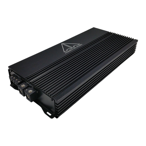
Addictive audio F300.1 Service manual

1

Specifications
F300.1 (13.8V)STEREO BRIDGED
Signal to Noise Ratio >110dB
High Efficiency 88% THD: 0.05%
Lowest Recommended Load:
2ohm Mono
N/A
205x1 watts RMS @ 4ohm
300x1 watts RMS @ 2ohm
Do Not Operate at 1ohm Mono
F300.4 (13.8V) STEREO BRIDGED
Signal to Noise Ratio >110dB
High Efficiency88%THD: 0.03%
Lowest Recommended Load:
2ohm Stereo or 4ohm Mono
75x4 watts RMS @ 4ohm
110x4 watts RMS @ 2ohm
Do Not Operate at 1ohm Stereo
200x2 watts RMS @ 4ohm
Do Not Operate at 2ohm or
1ohm Bridged
_______________________________________________________
Common Design Features
Intelli35© Intelligent 3.5mm Input Circuitry for Addictive Audio mini-BAR©
FLEXINputs© Flexible Input s and Outputs to Prevent Vibration Damage
Short Circuit, Thermal, Low / High / Reverse Voltage Protection
C2C ReverseLoc© Aluminum Heatsink for Max. MOSFET Heat Dissipation
INFINIFLO© Provides Strategic Air Flow over Key Components
Input Sensitivity: 220mV – 6 Vrms
Low Pass Filter: 50 – 250Hz (-12dB/Octave)
High Pass Filter: 25 – 250Hz (-12dB/Octave)
Subsonic Filter: 10 – 55Hz (-12dB/Octave)
Bass Boost from 0 to +18dB (45Hz)
3 Channel Operation with RCA/3.5mm Bridge Capabilities (F300.4)
Laser Etched Logo (Not another Peel-n-Stick amp)
Heavy Duty 4oz Copper Trace PCB Board
Direct Cable Connection for Superior Conductivity
Congratulations!
Selecting fine audio equipment, such as the Addictive Audio unit you have just
purchased, is only the beginning of your musical enjoyment. Now is the time to
consider how to maximize the fun and excitement your equipment has to offer.
Addictive Audio and the Electronic Industry Associations Consumer Electronic Group
want you to get the most out of your equipment by playing it at a safe level, a level that
lets the sound come through loud and clear without annoying blaring distortion; most
importantly, without affecting your sensitive hearing.
Sound can be deceiving over time your hearing “comfort level” adapts to higher
volumes of sound, what may have sounded “normal” can actually be too loud and
harmful to your hearing.
Prevent this by setting your equipment at a safe level BEFORE your hearing
adapts.
2

To establish the “safe level”.
• Start your volume control at a low setting.
• Slowly increase the sound until you can hear it comfortably and clearly, and
without distortion.
• Once you have established a comfortable “sound level” make a note of this
position and do not go above this setting.
Taking a minute to do this will help to prevent hearing damage in the future.
After all, we want you listening for a lifetime.
Introduction
Your ADDICTIVE AUDIO amplifier has been designed to give you very high
performance, and valuable features, at a very reasonable price. Take the time to
read over this brief set of instructions, and you will get full enjoyment from your
system.
Installation
The quality of the installation will affect system performance and reliability. You
may wish to contact a dealer or professional installer. The amplifier is generally
mounted in the rear trunk area but can be mounted in any convenient area such as
beneath a seat. Please be sure to locate this unit where you have reasonable air
circulation and protection from any moisture.
When considering the mounting location you should minimize the length of the
power supply and speaker leads. Minimizing both leads will provide higher audio
output from the system. It is important to ensure that the heat sink is not against a
panel or a surface preventing air circulation. Mark the location for the mounting
screw holes by using the amplifier as a template. Drill #29 or 9/64” diameter holes
at the marked locations and firmly fasten the amplifier in place with the mounting
screws supplied in the accessory kit.
Caution
Before drilling or cutting any holes investigate the layout of your automobile
thoroughly! Take care when working near the gas lines, hydraulic lines and
electrical wiring.
WARNING
This power amplifier has a protection feature to prevent any damage from misuse
or faulty conditions - excessive heat, short circuit speakers or overload. If the unit
senses one of the above conditions, the protection indicator will light and the
system will shut down. To diagnose the problem turn all levels down, all power off
and check the installation for possible wiring mistakes or shorts. In the event the
amplifier shuts down due to excessive heat under adverse conditions simply allow
time for the unit to cool down at which time, the protection indicator will not light.
3

Power Supply Connections
The +12VDC and GROUND wires should be heavy gauge copper wire with heavy
insulation and of the same gauge. Please see the chart below for recommended
gauge and fuse.
F300.4 60 AMP FUSE 8 GAUGE
F300.1 60 AMP FUSE 8 GAUGE
In addition, it has a 12V remote control wire and it should be 14AWG-18AWG.
It is preferable to have longer speaker wires and shorter power supply wires to
minimize power losses.
+12V Power (+12V)
This wire is usually connected directly to the positive battery terminal. Be sure to
use proper fuse as rated above within 16 inches of the main battery.
(Refer to Fig. 1)
Ground (GND) Same gauge as +12V and no longer than 36”
This connection must be completed using an “O” ring (to prevent coming loose)
with insulating sleeve. This wire is the electrical ground and must be fastened
securely to the vehicle chassis. The best method is to use threading sheet metal
screw(s) since the threads cut into bare metal. Ensure that all paint coating or
other insulation is removed from around the ground area. Use as short of a piece
of cable as possible – Again, use the same gauge as the +12V. (Refer to Fig. 1)
Remote (REM)
Many source units (cd player) or other music sources have an output terminal for
connection of the remote turn-on of the power amplifier. If the source unit doesn’t
have a remote turn-on feature, then you can connect the remote wire to a switch
that derives power from an ignition switched circuit. (Refer to Fig. 1)
Caution
First make +12V wire connection then the ground connection and finally the
remote connection. Furthermore the +12V wire must always be fused at the
battery for protection against possible damage. If you need to replace the power
fuse, replace it with a fuse of the same value. Using a fuse of a different type or
rating may result in a serious hazard.
4

FIG.1
Signal Input Connections
Signal Input (RCA) “Input”
Addictive Audio amplifiers have RCA connection type input terminal for low
level input. A standard pair of RCA type cables can be used for all models (Refer to
Fig. 2). Adjustment of input level is accomplished by the gain control. Adjusting this
control allows the amplifier gain to be controlled to match the source unit.
NOTE: For F300.4 set 2CH/4CH switch to “2CH” when running two separate sets
of RCA cables. When running a single pair of RCA cables set 2CH/4CH switch to
“4CH” to allow signal to pass through to all channels.
5

Signal Input (3.5MM) “AUX”
DO NOT USE AUX INPUTS WHEN USING RCA INPUTS and VISA VERSA.
Addictive Audio FLECK amplifiers also have 3.5 connection type input terminals.
This allows for easily connecting a mobile media player or the Addictive Audio
mini-BAR (for wireless streaming) without having to use a source unit. Adjustment
of input level is accomplished by the gain control. Adjusting this control allows the
amplifier gain to be controlled to match the source unit.
NOTE: For F300.4 set 2CH/4CH switch to “2CH” when running two separate
3.5mm cables. When running a single 3.5mm cable set 2CH/4CH switch to “4CH”
to allow signal to pass through to all channels.
COOL NOTE: When running an F300.4 and an F300.1 amplifier in a single
installation, use Y35 adaptor (sold separately) to allow a single source (mobile
phone or Addictive Audio mini-BAR) to send signal to both amplifiers. BE SURE
TO SET 2CH/4CH SWITCH ON THE F300.4 to “4CH” TO ALLOW SINGLE INPUT
TO BE PASSED THROUGH TO ALL CHANNELS.
6

Speaker Output Connections
F300.1: 2ohm and 4ohm Stable ONLY – DO NOT RUN AT 1ohm.
When wiring a single subwoofer to the amplifier, combine both
positive (+) wires to the positive (+) wire of the subwoofer and both
negative (-) wires to the negative (-) wire of the subwoofer.
F300.4:
4 CHANNEL CONNECTION: Connect each pair of speaker wires to
each individual set of speaker connections. 2ohm and 4ohm
STEREO ONLY.
3 CHANNEL CONNECTION: (Front=Mids/Highs and Rear=Sub)
Connect the front two speakers to each individual set of speaker
connections. 2ohm and 4ohm STEREO ONLY. Bridge channels 3
and 4 to the subwoofer by using R+ and L- outputs. 4ohm
BRIDGED ONLY.
2 CHANNEL CONNECTION:
Bridge channels 1 and 2 to the speaker by using front R+ and L-
outputs. Bridge channels 3 and 4 to the speaker by using rear R+
and L- outputs. 4ohm BRIDGED ONLY.
7

Amplifier Features and Controls
1. Power / Protection
POWER LED: Will illuminate BLUE when +12VDC is applied to both the remote turn on
and +12V input from the battery and a solid ground has been made. The input
from the battery to the amplifier can be more than 12VDC.
PROTECTION: Will illuminate RED when any one of the following occurs:
Short Circuit (Immediately)
Reverse Voltage (Immediately)
Thermal (On at 141*F or 60*C)
Low Voltage (On at 9VDC)
High Voltage (On at 16VDC)
2. REMOTE
Plug the remote bass knob into this port on the 5 channel amplifier for
independent subwoofer control.
8

3. Low Pass Filter
This controls the low pass crossover point for the speaker outputs. This
crossover, when selected, will attenuate the frequencies above the
crossover point with a slope of -12dB per octave The crossover point is
adjustable from 50-250Hz. This filter reduces unwanted upper frequencies
from being played through the subwoofer(s).
4. Bass Boost
This allows the ability to Boost low frequency response (45Hz)up to +18dB.
5. Subsonic Filter
Control the high pass crossover point for the speaker outputs to eliminate
ultra low frequencies. This crossover is always on with a -12dB per octave
slope and adjustable from 10-55Hz. This filter is used mainly in ported
applications, to protect the subwoofers from excessive excursion below
the port tuned frequency. Not necessary when dealing with sealed
enclosures, but can still be used to help protect the subwoofer system.
6. Gain Level Control *NOT A VOLUME KNOB*
This allows for the adjustment of the gain of both channels to match the
output level of the source unit. In addition, it allows adjustment from 0.2V
to 6.0V.
7. 3.5mm “AUX” Input Jacks
DO NOT USE AUX INPUTS WHEN USING RCA INPUTS and VISA
VERSA. Addictive Audio FLECK amplifiers also have 3.5 connection type
input terminals. This allows for easily connecting a mobile media player or
the Addictive Audio mini-BAR (for wireless streaming) without having to
use a source unit. Adjustment of input level is accomplished by the gain
control. Adjusting this control allows the amplifier gain to be controlled to
match the source unit.
8. RCA Line Input Jacks
Addictive Audio amplifiers have RCA connection type input terminal for low
level input. A standard pair of RCA type cables can be used for all models
9

Adjustment of input level is accomplished by the gain control. Adjusting
this control allows the amplifier gain to be controlled to match the source
unit.
9. 2CH/4CH Signal Pass-Through Selection Switch
For F300.4 set 2CH/4CH switch to “2CH” when running two separate
RCA/AUX cables. When running a single RCA/AUX cable set 2CH/4CH
switch to “4CH” to allow signal to pass through to all channels.
10. MODE
LPF: Set the MODE SWITCH to the LPF position when the amplifier is used to drive a
subwoofer system. The frequencies above the crossover point will be attenuated
at -12dB/octave. Adjust the crossover frequency by rotating the LPF knob to the
desired frequency ranging from 50-150Hz. See #5 below for more details.
FULL: Set the MODE SWITCH to the FULL position when the amplifier is used to drive full-
range speakers and/or components that come with their own crossover. The full
frequency bandwidth will be output to the speakers without high or low frequency
attenuation.
11. High Pass Filter
This controls the high pass crossover point for the speaker outputs. This
crossover, when selected, will attenuate the frequencies below the
crossover point with a slope of -12dB per octave The crossover point is
adjustable from 25-250Hz. This filter reduces unwanted lower frequencies
from being played through the speaker(s).
Adjusting the Amplifier
1. Disconnect the negative battery post and secure it to something so
accidental re-connection does not occur during the installation process.
2. Run all wires needed for the amplifier to work correctly. Do not attach the
fuse in the fuse holder by the battery until all wires have been plugged into
the amplifier.
3. Turn the amplifiers gain and boost all the way down (counter clockwise).
4. As a good “starting point” set phase to 0, subsonic and other adjustment
knobs all the way down (counter clockwise) and mode switches to the
correct MODE being used.
5. Attach the recommended fuse (refer to fuse chart on pg.4) to the fuse holder by
the main battery.
10

6. Re-attach the negative battery post from step 1.
7. Turn the head unit on and start at a low volume. Check amplifier to make
sure all wires are correct and no protection lights are on.
8. Set the head unit’s tone controls, balance, and fader to the center or flat
position. Be sure to turn off any loudness or other signal processors.
9. Use a very clear original recording not mp3 or burned cd. Turn the volume
of the head unit to its maximum undistorted volume. On most quality head
units this is around 7/8 of the maximum volume.
10. Slowly turn up the gain (clockwise) to match the voltage output of the head
unit or until the speakers reach the maximum undistorted output.
11. Adjust the low pass, high pass, subsonic filters and phase to desired
settings.
12. Play a few different selections of music to check for overall system
balance.
13. ENJOY!
NOTE: Many vehicles have small and insufficient wire to connect the alternator’s positive
connection to the battery and to ground the battery to the vehicle chassis. To prevent
voltage drops, these wires should be upgraded to 4-0 AWG when installing one or more
Addictive Audio amplifiers.
11

12

NOTES
Many vehicles have small and insufficient wire to connect the alternator’s positive
connection to the battery and to ground the battery to the vehicle chassis. To prevent
voltage drops, these wires should be upgraded to 4-0 AWG when installing one or more
Addictive Audio amplifiers.
____________________________________________________
____________________________________________________
____________________________________________________
____________________________________________________
____________________________________________________
____________________________________________________
____________________________________________________
____________________________________________________
____________________________________________________
____________________________________________________
____________________________________________________
____________________________________________________
____________________________________________________
____________________________________________________
____________________________________________________
____________________________________________________
____________________________________________________
____________________________________________________
____________________________________________________
____________________________________________________
____________________________________________________
____________________________________________________
____________________________________________________
____________________________________________________
13

STAY UP TO DATE ON NEW PRODUCTS, PROTOTYPES,
RELEASE DATES AND OTHER COOL STUFF!
SEARCH: Addictive Audio Inc on FACEBOOK.com
WATCH THE LATEST AND GREATEST VIDEOS OF
ADDICTIVE AUDIO, KROME AUDIO AND VITAL POWER
PRODUCTS!
SEARCH: Addictive Audio Inc on YOUTUBE.com
14
This manual suits for next models
1
Table of contents
Other Addictive audio Amplifier manuals

