Eneo VDA-4A User manual
1
Montage- und Betriebsanleitung
Video-Verteiler VDA-4A und VDA-8CA
Installation and Operating Instructions
Video Distribution Amplifier VDA-4A and VDA-8CA
Mode d’emploi
Commutateur Vidéo VDA-4A et VDA-8CA
Instrucciones de manejo
Conmutador Video VDA-4A y VDA-8CA
VDA-4A VDA-8CA

2
Inhaltsverzeichnis
1. Sicherheitshinweise ............................................. 3
2. Allgemeine Beschreibung..................................... 3
3. Beschreibung der Anschlüsse .............................. 4
4. Installation ........................................................... 5
4.1 Anschlussmöglichkeiten ...................................... 5
4.2 Ein-/Ausgangssignal-Konfiguration (VDA-8CA) ..... 6
4.3 Ausgangssignal-Voranhebung .............................. 7
5. Technische Daten ................................................ 8
Sommaire
1. Consignes de sécurité ........................................ 15
2. Description générale .......................................... 15
3. Description des connexions ............................... 16
4. Installation ......................................................... 17
4.1 Possibilités de raccordement ............................. 17
4.2 Configuration des signaux d’entrée/sortie
(VDA-8CA).......................................................... 18
4.3 Préaccentuation du signal de sortie ................... 19
5. Caractéristiques techniques ............................... 20
Contents
1. Safety Instructions ............................................... 9
2. General Descriptions ............................................ 9
3. Descriptions of the connections ......................... 10
4. Installation ......................................................... 11
4.1 Connections ....................................................... 11
4.2 Input / output configuration (VDA-8CA) ............... 12
4.3 Output signal range (Gain Adjustment) ............... 13
5. Specifications .................................................... 14
Contenido
1. Indicaciones de seguridad.................................. 21
2. Descripción general ........................................... 21
3. Descripción de las conexiones ........................... 22
4. Instalación ......................................................... 23
4.1 Posibilidades de conexión ................................. 23
4.2 Configuración de la señal de entrada/salida
(VDA-8CA).......................................................... 24
4.3 Pre-amplificación de la señal de salida.............. 25
5. Datos técnicos ................................................... 26
Betriebsanleitung
Installation and Operating Instructions
Mode d’emploi
Instrucciones de manejo
www.eneo-security.com/manuals
⇒

3
1. Sicherheitshinweise
• Bevor Sie die Anlage in Betrieb nehmen, lesen Sie zuerst diese Sicherheitshinweise und die Betriebsanleitung.
• Bewahren Sie die Betriebsanleitung sorgfältig zur späteren Verwendung auf.
• Kontrollieren Sie, ob die Spannungsversorgung mit den Angaben auf dem Typenschild übereinstimmen.
• Das Gerät ist nur für den Betrieb in geschlossenen Räumen vorgesehen und darf weder Regen noch Feuchtigkeit
ausgesetzt werden.
• Achten Sie beim Verlegen des Anschlusskabels unbedingt darauf, dass es nicht belastet, geknickt oder beschädigt
wird und keine Feuchtigkeit eindringen kann.
• Die Schutzleiterverbindung muss DIN VDE 0100 entsprechend niederohmig ausgeführt sein.
• Die Einstellung der Steckbrücken (VDA-8CA) sowie der Potentiometer, sollte entsprechend geschultem Fach-
personal vorbehalten sein.
• Vor Beginn von Servicearbeiten ist die Versorgungsspannung vom Gerät zu trennen.
• Die Geräte dürfen nicht höher abgesichert werden, als es außen am Gehäuse vermerkt ist.
• Das Gehäuse darf nur durch dafür autorisierte Personen geöffnet werden. Fremdeingriffe beenden jeden
Garantieanspruch.
• Falls Funktionsstörungen auftreten, benachrichtigen Sie bitte Ihren Lieferanten.
2. Allgemeine Beschreibung
• Die Verteilerverstärker der VDA-Serie ermöglichen die verlustfreie Verzweigung hochfrequenter S/W, bzw.
Farbvideosignale auf mehrere Ausgänge.
• Mit dem Typ VDA-4A kann das Quellensignal auf bis zu vier Kanäle verteilt werden; dabei ist, gemeinsam für alle
Ausgänge, eine stufenlose Signalvoranhebung, bzw. die Vorentzerrung von kabelabhängigen Verlusten über
Potentiometer möglich.
• Der Typ VDA-8CA lässt eine bedarfsabhängige Ein-/Ausgangskonfiguration zu. Die 4 Eingänge lassen sich in
unterschiedliche Kombinationen auf die 8 Ausgänge konfigurieren. Bei diesem Typ ist eine stufenlose Signalvor-
anhebung/Kanal vorhanden.
• Die Verteilerverstärker verfügen über ein robustes Metallgehäuse und eine von außen zugängliche Netzsicherung.
• Alle Signale sind steckbar über Standard-BNC-Buchsen geführt.
• Mit dem optionalen 19”-Einbausatz ist eine 19”-Schrankmontage des VDA-8CA möglich.

4
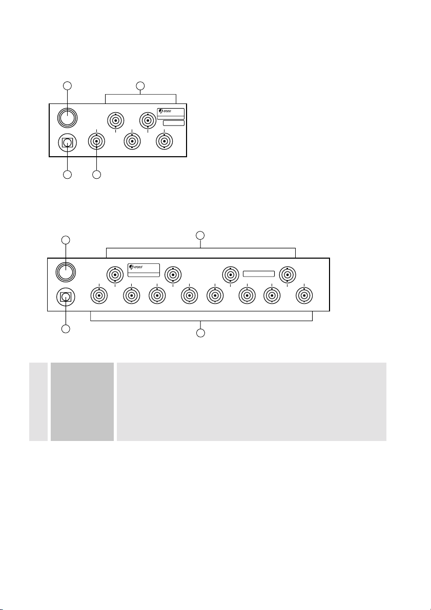
3. Beschreibung der Anschlüsse
Rückseite VDA-4A
1Sicherung T 315 mA
2Videoeingänge BNC-Buchsen
3Netzeingang Die Stromversorgung darf erst hergestellt werden, nachdem alle Geräte
angeschlossen sind.
4Videoausgänge BNC-Buchsen
Rückseite VDA-8CA
Ser.No:
230V ~ 50Hz 3W
MODEL: VDA-4A
1
3
2
1
VIDEO OUT
VIDEO IN
T
315mA
AC
IN
FUSE
1
3
4
2
Ser.No:
VIDEO OUT
VIDEO IN
T315mA
AC
IN
FUSE
1
34
2
1
2-1
3
1-2
1-1 2-2
2
1-3 2-3 1-4
4
2-4
230V ~ 50Hz 6W
MODEL: VDA-8CA

5
KAM Video-Eingänge Anschluss des ankommenden Signals (Kamera, Videoquelle; 75 Ohm)
(VIDEO IN)
MON Video-Ausgänge Anschluss der abgehenden Signale (Monitor, VCR, Printer etc.)
VCR (VIDEO OUT)
AC IN Netzeingang Netzstecker in Steckdose (230 VAC) stecken.
4. Installation
4.1 Anschlussmöglichkeiten
VDA-4A
VDA-8CA
Ser.No:
230V ~ 50Hz 3W
MODEL: VDA-4A
1
3
2
1
VIDEO OUT
VIDEO IN
T
315mA
AC
IN
FUSE
Ser.No:
VIDEO OUT
VIDEO IN
T315mA
AC
IN
FUSE
1
2-1
3
1-2
1-1 2-2
2
1-3 2-3 1-4
4
2-4
230V ~ 50Hz 6W
MODEL: VDA-8CA
VCR MON
MON
MON
KAM
230 VAC / 50 Hz
KAM
230 VAC / 50 Hz
KAM KAM KAM
MON
VCR
MON
MON
MON MON
VCRVCR
6
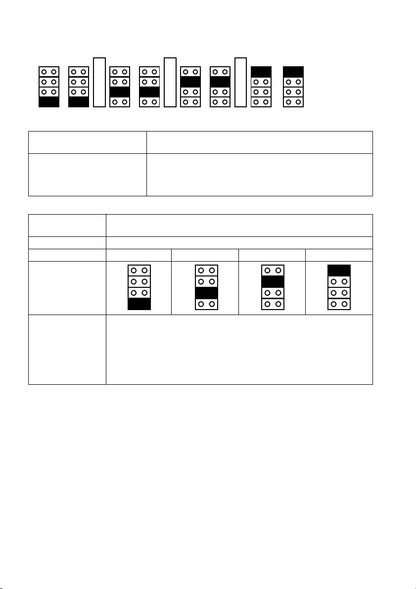
Vorgehensweise Am Video-Ausgang 1 (J201) werden durch das Setzen der Steckbrücken 1-4 die Video-
Eingänge konfiguriert.
Video-Ausgang Video-Eingänge (Steckbrückenposition)
12 3 4
1 (J201)
2 (J211) Mit den Video-Ausgängen 2-8 wird wie unter 1 (J201) beschrieben verfahren.
3 (J221)
4 (J231)
5 (J241)
6 (J251)
7 (J261)
8 (J271)
4.2 Ein-/Ausgangssignal-Konfiguration (VDA-8CA)
Programmierung der Interne Steckbrücken ermöglichen die Bestimmung einer Vielzahl
Signal-Konfigurationen von Konfigurationen der Video-Ein- und Ausgänge.
Mögliche Konfigurationen 4x 1E / 2A (siehe Beispiel oben)
2x 1E / 4A
1E / 6A und 1E / 2A
1x 1E / 8A
OUT7
J261
OUT8
J271
OUT5
J241
OUT6
J251
OUT3
J221
OUT4
J231
OUT2
J211
OUT1
J201
IN
4
3
2
1
IN
4
3
2
1
IN
4
3
2
1

7
4.3 Ausgangssignal-Voranhebung
VDA-4A
TP301 TP302
VDA-4A Einstellung gemeinsam für alle 4 Ausgänge
TP301: Vorentzerrung hoher Frequenzen für den Ausgleich der durch die
Kabellängen bedingten, frequenzabhängigen Signalverluste
TP302: Lineare Signalvoranhebung
Hinweis:
TP101 dient der Arbeitspunkteinstellung, ist werkseitig fest abgeglichen
und darf nicht verändert werden.
VDA-8CA Lineare Signalvoranhebung:
TP201: für Ausgang 1
TP211: für Ausgang 2
TP221: für Ausgang 3
TP231: für Ausgang 4
TP241: für Ausgang 5
TP251: für Ausgang 6
TP261: für Ausgang 7
TP271: für Ausgang 8
VDA-8CA
TP211 TP231 TP251 TP271
TP201 TP221 TP241 TP261

8
5. Technische Daten
Typ VDA-4A VDA-8CA
EDV-Nr. 75101 75102
Verteiler-Konfiguration 1 Eingang / 4 Ausgänge 4x 1E/2A; 2x 1E/4A; 1E/6A und 1E/2A;
1E/8A
Videoeingänge 1,0-2,0 Vss F(BAS), 75 Ohm, BNC Bis zu 4x 1,0-2,0 Vss F(BAS), 75 Ohm,
BNC
Videoausgänge 4x 1,0-2,0 Vss (F)BAS, 75 Ohm, BNC Bis zu 8x 1,0-2,0 Vss (F)BAS, 75 Ohm,
BNC
Videobandbreite 0 – 10 MHz (+/- 3 dB)
Signal/Rauschabstand > 55 dB
Kabellängen-Vorentzerrung 0 – 6 dB stufenlos einstellbar –
(gemeinsam für alle Ausgänge)
Signal-Voranhebung 0 – 6 dB stufenlos einstellbar -6 bis +6 dB stufenlos einstellbar
(gemeinsam für alle Ausgänge) (getrennt für jeden Kanal)
Dachschräge </= 1% bei 50 Hz
Interne Einstellungen Je 1 Potentiometer 4 Steckbrücken / Kanal für die Zuordnung
für die stufenlose Signal-Voranhebung, der Ausgänge zu den Eingängen.
bzw. HF-Verstärkung Je 1 Potentiometer für die stufenlose
Ausgangs-Signal-Voranhebung
Betriebsspannung 230 VAC / 50 Hz
Leistungsaufnahme Ca. 3 W Ca. 6 W
Temperaturbereich 0°C bis +50°C
Gehäuse Stahlblech
Farbe Pantone Coolgrey 1C
Abmessungen (H x B x T) 44 x 108 x 135 mm 44 x 216 x 240 mm
Gewicht Ca. 600 g 2,5 kg
Zubehör
EDV-Nr. Typ Kurzbeschreibung
76407 VDA/AVU-RMK1 19”-Einschub für 1x VDA-8CA oder AVU-8/2AL-2
76408 VDA/AVU-RMK2 19”-Einschub für 2x VDA-8CA oder AVU-8/2AL-2

9
1. Safety instructions
• Please read these safety and operating instructions before putting the system into operation.
• Keep the operating instructions in a safe place for later use.
• Use only the specified power source specified on the rating label located on rear of the cabinet.
• Avoid using this unit under the following conditions: in extremely hot, cold or humid places, near appliances
generating strong magnetic fields, and in places subject to direct sunlight
• Pay attention when laying the connection cable and observe that the cable is not subject to heavyloads, kinks,
or damage and that no moisture can get in.
• The safety earth connection must have low conformity with the electrical safety regulations.
• The unit may only be opened by authorized personnel. Adjustments of the internal jumper and potentiometers
should be carried out by a qualified technician.
• Before opening the unit disconnect from mains voltage.
• Do not use an higher fuse value as it is labelled at the fuse holder.
• The warranty becomes void if repairs are undertaken by unauthorized persons.
• Unplug this unit from power supply and refer servicing to qualified service personnel under following conditions:
if the unit does not operate normally following the operating instructions, if the unit has been dropped or the
cabinet has been damaged when the unit exhibits a distinct change in performance.
• Contact your local dealer in case of malfunction.
2. General Descriptions
• The signal distributors of the VDA series provide the lossfree distribution of high frequent b&w and colour video
signals to several outputs.
• VDA-4A can distribute the input signal to up-to 4 outputs. Additional it allows for all output channels a stepless
signal amplification and pre-equalization via potentiometer.
• VDA-8CA is configurable, severall combinations exist to link the 4 inputs to the 8 outputs.
This unit allows a stepless signal amplification per output channel.
• The distributor units are contained in a stable steel metal cabinet with integrated 230 V power supply and a,
from outside accessible, mains fuse.
• All video signal are plugable via BNC sockets.
• Rack mountable using the optional 19” rack mount kit (VDA-8CA only).
10
3. Description of the connections
Rear side VDA-4A
1Fuse socket T 315 mA
2Video input BNC-connector
3Power cord Be sure to disconnect the power plug from the AC outlet before connecting to other
equipment
4Video output BNC-connector
Rear side VDA-8CA
Ser.No:
230V ~ 50Hz 3W
MODEL: VDA-4A
1
3
2
1
VIDEO OUT
VIDEO IN
T
315mA
AC
IN
FUSE
1
3
4
2
Ser.No:
VIDEO OUT
VIDEO IN
T315mA
AC
IN
FUSE
1
34
2
1
2-1
3
1-2
1-1 2-2
2
1-3 2-3 1-4
4
2-4
230V ~ 50Hz 6W
MODEL: VDA-8CA
Other manuals for VDA-4A
1
This manual suits for next models
1
Table of contents
Languages:
Other Eneo Amplifier manuals


