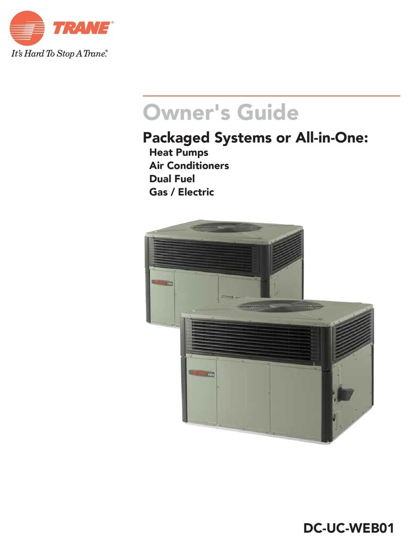
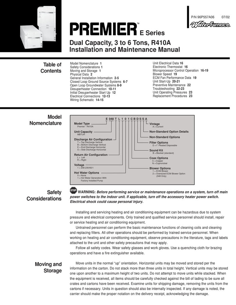
Addison DC Series User manual

1
WARNING: READ SAFE OPERATION RULES AND MANUAL CAREFULLY
INSTALLATION OPERATION and MAINTENANCE MANUAL
High Efficiency Packaged Models DC Series B, Air Conditioning
Systems, Model Sizes 036 Thru 420
No Heat Recovery Cabinet
Extended Heat Recovery Cabinet
TABLE OF CONTENTS
Safety Labeling and Signal Words...........2
General Description ..................................3
Unpacking, Inspection ........................3
Design Certification..............................3
Codes & Ordinances ............................3
Installation..............................................3- 6
Unit Location, Clearances ...................3
Curb Installation ...................................3
Rigging...................................................4
Electrical................................................4
Ductwork ...............................................5
Condensate Piping...............................5
Gas Piping and Venting ...................5- 6
Cooling System Options.......................6- 8
Hot Gas Bypass ....................................6
Head Pressure Control.........................6
Variable Speed Control........................6
Adjustable High and Low Pressure....7
Hot Water Heat Recovery.................7, 8
Mechanical Adjustments ....................9, 10
Evaporator Blower Fan ..................9, 10
Electrical System Options......................10
Air Flow Switch...................................10
Clogged Filter Indicator..........................10
Convenience Outlet............................10
Exhaust Fan Interlock ........................10
Power Through the Curb ...................10
Firestat.................................................10
Sure-TripTM ..........................................10
DDC controls.......................................10
Sequence of Operation...........................11
Heating, Steam/Hydronic...................11
Gas Heat..............................................11
Electric Heat........................................11
Energy Conservation Wheel..............12
Trouble Shooting Guides...................13-18
General Refrigeration Circuit .......13-16
Varispeed™ Condenser Control.......15
Hot Gas Bypass Regulator................16
Gas Furnace........................................17
!
R410A

Insert for all ADDISON®product manuals
Instructions:
In accordance with California Proposition 65 requirements, place enclosed label(s) in a highly visible location on outside of
equipment to be repaired (i.e., near equipment’s serial plate). See label placement drawing in equipment’s Installation, Op-
eration and Service manual for label location (when available). Avoid placing label on areas with extreme heat, cold, corro-
sive chemicals or other elements. Extra labels are also included where repair of multiple units is involved. To order additional
labels, please call +1.407.292.4400.
To obtain a copy of the manual or for more information, visit the applicable website(s) below:
Incluya en todos los Manuales de productos de ADDISON®
Instrucciones:
De conformidad con los requerimientos de la Propuesta 65 de California, ubique la(s) etiqueta(s) adjunta(s) en un lugar bien
visible en el exterior del equipo a ser reparado (es decir, cerca de la placa serial). Ver dibujo de instalación de la etiqueta en
el Manual de Operaciones y Mantenimiento (si esta disponible). Evite colocar la etiqueta en áreas con calor, frío, productos
químicos corrosivos u otros elementos. Se incluyen etiquetas adicionales para el caso de reparación de varias unidades.
Para ordenar etiquetas adicionales, por favor llamar al +1.407.292.4400.
Para obtener una copia del manual o para obtener mas información visite los sitios Web correspondientes a continuación.
www.addison-hvac.com
Código de Instalación e Inspecciones Anuales: Todas las instalaciones y mantenimientos de productos
ADDISON
®
deben ser realizados sólo por personal cualificado en la instalación y mantenimiento de los equipos
vendidos y suministrados por Addison y/o por sus distribuidores y deben cumplir con todos los requisitos
dispuestos en los manuales de ADDISON
®
y con todos los estándares locales aplicables a la instalación,
mantenimiento, funcionamiento y etiquetado del equipo. Para conseguir un funcionamiento óptimo y seguro,
Addison recomienda que un técnico cualificado revise anualmente sus equipos y realice el mantenimiento
siempre que sea necesario, usando exclusivamente piezas de repuesto de ADDISON
®
.
Información adicional: A través de los distribuidores de Addison está disponible la información sobre
aplicaciones, guías detalladas sobre diseño de sistemas e instalación y funcionamiento de los productos. Por
favor contacte con nosotros si necesita más información o si requiere un manual de instalación,
funcionamiento y mantenimiento.
Este producto no es para uso residencial.
La intención de este documento es la de ayudar a los profesionales autorizados en el libre ejercicio de su
profesión.
Installation Code and Annual Inspections: All installation and service of ADDISON
®
equipment must be performed by a contractor qualified in the
installation and service of equipment sold and supplied by Addison and conform to all requirements set forth in the ADDISON
®
manuals and all applicable
governmental authorities pertaining to the installation, service, operation and labeling of the equipment. To help facilitate optimum performance and
safety, Addison recommends that a qualified contractor conduct, at a minimum, annual inspections of your ADDISON
®
equipment and perform service
where necessary, using only replacement parts sold and supplied by Addison.
Further Information: Applications, engineering and detailed guidance on systems design, installation and equipment performance is available through
ADDISON
®
representatives. Please contact us for any further information you may require, including the Installation, Operation and Service Manual.
This product is not for residential use.
This document is intended to assist licensed professionals in the exercise of their professional judgment.
www.addison-hvac.com Printed in U.S.A. P/N 91070020 Rev B 03/12
Page 1 of 1
© 2012 Addison All rights reserved. No part of this work covered by the copyrights herein may be reproduced or copied in any form or by any means –
graphic, electronic, or mechanical, including photocopying, recording, taping, or information storage and retrieval systems – without
written permission of Addison.
Addison
7050 Overland Road
Orlando, FL 32810 U.S.A.
Telephone: +1.407.292.4400
Fax: +1.407.290.1329
www.addison-hvac.com

2
Form #527I-1053 (0703)
SAFETY LABELING AND SIGNAL WORDS
Danger, Warning and Caution
The signal words DANGER, WARNING and
CAUTION are used to identify levels of hazard
seriousness. The signal word DANGER is only
used on product labels to signify an immediate
hazard. The signal words WARNING and
CAUTION will be used on product labels and
throughout this manual and other manuals that
may apply to the product.
Signal Words
DANGER – Immediate hazards which WILL
result in severe personal injury or death.
WARNING – Hazards or unsafe practices
which COULD result in severe personal injury
or death.
CAUTION – Hazards or unsafe practices which
COULD result in minor personal injury or
product or property damage.
Signal Words in Manuals
The signal word WARNING is used throughout
this manual in the following manner:
The signal word CAUTION is used throughout this
manual in the following manner:
CAUTION
Product Labeling
Signal words are used in combination with colors and/or
pictures on product labels. Following are examples of
product labels with explanations of the colors used.
WARNING
Electric Shock Hazard.
Turn Off All Power
Before Servicing.
DANGER
!
Fire Hazard.
Use copper wire only.
Failure to observe could
result in property
damage, bodily injury or
death.
WARNING
!
Cuts and Abrasion Hazard.
Wear gloves and handle
with care.
Failure to observe could
result in bodily injury.
CAUTION
!
WARNING
Danger Label
White lettering on a black background except the word
DANGER which is white with a red background.
Warning Label
White lettering on a black background except the word
WARNING which is white with an oran
g
e back
g
round.
Caution Label
White lettering on a black background except the word
CAUTION which is white with a yellow background.
!
This unit contains chlorodifluoromethane (HFC-22), a substance that harms public health and environment by
destroying ozone in the upper atmosphere.
DO NOT VENT HCFC-22 to the atmosphere. The U. S. Clean Air Act requires the recovery of any residual
refrigerant.
!

3
GENERAL DESCRIPTION
The model DC Series B packaged cooling and heating
unit is designed to cool a conditioned space with
mechanical refrigeration, chilled water, energy
conservation wheel or a combination of these systems.
During the heating mode supply air may be heated by
indirect fired gas, electric strip, steam or hot water. The
cabinet design provides space for a number of options,
including 100% outside air applications and the use of
desiccant wheels. Most of these options will be covered in
this manual; for those of a more custom nature, consult the
ADDISON Application Engineering Department.
Models DC units are designed for rooftop curb, slab
mounted or installed on post and rail applications with field
convertible vertical or left and right horizontal return and
supply air duct connections.
Unpacking, Inspection
When received, the unit should be checked for damage
that might have occurred in transit. If damage is found, it
should be noted on the carrier’s Freight Bill. Request for
inspection by carrier’s agent should be made in writing at
once.
Design Certification
All units are certified by Electrical Testing Laboratories
(E.T.L.) under ANSI/UL 1995. The gas furnace designs are
certified by E.T.L. under ANSI Z83.9 (latest edition) for use
with natural or propane (L.P.) gas as specified when
ordering unit.
Codes and Ordinances
These units must be installed in accordance with the
standard of the National Fire Protection Association or the
National Fuel Gas Code ANSI Z83.9 (latest edition). The
National Fuel Gas Code is available from the American
Gas Association, 1515 Wilson Boulevard, Arlington, VA
22209. NFPA Publications are available from the National
Fire Protection Association, Batterymarch Park, Quincy,
MA 02269. Local authorities having jurisdiction should be
consulted before installations are made to verify local
codes and installation procedures.
All field wiring to the unit must be done in accordance with
these instructions, the National Electric Code (ANSI/NFPA
70-1981) in the United States and all local codes and
ordinances.
Clearances from the heater and vent to construction or
material in storage must conform with the National Fuel
Gas Code ANSI Z83.9 (latest edition), pertaining to gas-
burning devices, and such material must not attain a
temperature over 160°F by continued operation of the
heater.
Installation should be done by a qualified agency in
accordance with the instructions in this manual and in
compliance with all codes and requirements of authorities
having jurisdiction.
INSTALLATION
Unit Location, Clearances
An intake louver protects the service end and clearance at
this point should be maintained. A 36" clearance must be
allowed for access to the compressor and electrical panel.
A 24" clearance must be maintained for the air inlet to the
condenser coil(s). Do not locate the unit under an
overhang that will short circuit hot air to the coil intakes.
When installed at ground level, the unit should be mounted
on a level concrete slab which should extend at least 2"
beyond the unit on all sides. The top of the slab should be
2" above the ground level.
The depth of the slab below the ground level and its
structural design is governed by the type of soil and
climatic conditions. The slab must not be in contact with
any part of the building wall or foundation. The space
between the slab and building wall prevents the possibility
of transmitting vibration to the building.
The dimensions of the slab or roof mount should be
checked and verified before the equipment arrives. Unit
supports, roof opening, roof curb flashing, drain
requirements, and electric locations are important to a
good installation.
When installing the equipment on top of a building, the
following should be considered:
Structural members supporting the unit must be sufficiently
strong for the weight of the unit and mounting rails.
Transmission of sound into the building is sometimes a
problem when the structure is not strong enough.
Locate the unit as near as possible to the center of the
area to be environmentally controlled. Sufficient clearance
must be available for service, edge of roof, other units, or
hazards.
The condenser air inlet and discharge air must be
unobstructed by overhang, walls, or other equipment.
Avoid locations next to exhaust fans or flues.
Select a location where external water drainage cannot
collect around the unit.
Locate the unit so roof runoff water does not pour directly
on the unit. Provide gutter or other shielding at roof level.
Where snowfall is anticipated, mount the unit above the
maximum snow depth for the area.
Curb Installation, Protrusions
Proper installation for the DC series requires that the roof
mounting, field assembled curb be firmly and permanently
attached to the roof structure. Check for adequate
fastening method prior to setting rooftop unit on curb.
Inspect curb to insure that none of the utility services
(electric, gas, drain lines) routed through the curb protrude
above the curb. Duct connections will normally be made
after unit is set on curb. If duct is prefabricated and
installed within the curb prior to setting unit, insure that
ductwork does not protrude above curb.
CAUTION: DO NOT ATTEMPT TO SET UNIT ON CURB
IF PROTRUSIONS EXIST.
CAUTION: Units may look identical but have significant
internal differences.
Check specific unit location carefully (referring to plans if
necessary) prior to setting unit.

4
INSTALLATION CONTINUED
Rigging
WARNING: Be sure that the crane and lift material (bars,
cable, chain), (or other lifting device) capacity is adequate
for the unit weight. See Addison specification literature for
weights. The total unit weight calculated must include all
appropriate options for your unit. Certain options can add
significant weight to a unit.
Refer to labeling on unit for the required use of spreader
bars. Spreader bars keep the lift cables from damaging the
cabinet once the unit has been lifted. Larger units will
require a third or fourth support in the middle of the unit.
Keep the tension equal improper lift tension can damage
wiring, refrigeration lines and the water tight integrity of the
cabinet as well as sheet metal damage to the unit cabinet.
FRONT OF UNIT CENTER OF UNIT REAR OF UNIT
UNIT FRAME RIGGING CONNECTION POINTS
INSERT LIFT BAR
HERE (BOTH RAILS) HERE (BOTH RAILS)
INSERT LIFT BAR
DC SERIES B UNIT
STEEL BASE FRAME
FULL PARIMETER STRUCTURAL
USE A TEE LOOP OR
DO NOT USE A BAR!
HOOK TYPE LIFT
RIGGING MUST BE SUCH THAT EQUAL TENSION IS EXSERTED ON
ALL FRAME LIFT POINTS OR SEVERE UNIT DAMAGE WILL RESULT!
WARNING:
YOUR UNIT MAY VARY
FROM WHAT IS SHOWN
Figure 1
Lower unit carefully onto roof mounting curb or mounting
rails or ground level slab. While rigging unit, center of
gravity will cause condenser end to be lower than
supply/return air end. Bring condenser end of unit into
alignment with curb. With condenser end of unit resting on
curb member and using curb as fulcrum, lower front end of
unit until entire unit is seated on curb.
Rigging Removal
Remove spreader bars, lifting cables and other rigging
equipment. Use caution not to dent scratch or otherwise
damage cabinet or intake and exhaust hoods.
CAUTION: Do not allow crane hooks and spreader bars
to rest on roof of the unit.
ELECTRICAL
Wiring Connections
Power wiring should be connected to the main power
terminal block located within the unit main control section.
Power wiring connections on units with factory disconnects
should be made at the line side of the disconnect switch.
Low voltage wiring connections are made to the remote
mounted controller or time clock.
DO NOT TAMPER WITH FACTORY WIRING
Contact your local representative or the factory if
assistance is required. The internal power and control
wiring of these units is factory installed and each unit is
thoroughly tested prior to shipment.
Independent Power Source
It is recommended that an independent 115-volt power
source be brought to the vicinity of the rooftop unit for
portable lights and tools used by the service mechanic.
Main Power Wiring
The units are factory wired for the voltage shown on the
nameplate.
Main power wiring should be sized for the minimum wire
ampacity shown on the nameplate.
An external weather-tight disconnect switch properly sized
for the unit total load is required for each unit. Disconnect
must be installed in accordance with Local and/or National
Electric Codes.
Power wiring may enter the Rooftop Unit through the side
on all models or through the unit base and roof curbs on
models with the Power Through Curb option. Install
conduit connectors at the entrance locations. External
connectors must be weatherproof.
Grounding
All units must be properly grounded. The ground lug is
provided for this purpose. DO NOT use the ground lug for
connecting a neutral conductor. The unit must be
electrically grounded in accordance with local codes, or in
the absence of local codes, with the NEC ANSI/NFPA 70
1981.
Once it is established that supply voltage is within the
utilization range, check and calculate if an unbalanced
condition exists between phases. Calculate percent
voltage unbalance as follows:
Contact power company if phase unbalance exceeds 2%.
Control System Wiring: For commercial equipment the
following table lists the minimum size of 24 volt class 2
wire to be used.

5
Note: Wiring - Consult the wiring diagram furnished with
the unit. These units are custom designed for each application. The unit wiring diagram is located inside the
control panel of each unit.
INSTALLATION CONTINUED
Ductwork
Properly sized and installed ductwork is critical to reliable
performance of the unit and system. The DC Series B is
field convertible for down flow or left and right horizontal
supply and return duct connections. The DC Series B is
shipped from the factory with all duct connections capped
off. Simply remove the duct caps required for duct
installation. Unit connection sizes are in the engineering
specification literature. All ductwork must be installed
according to local codes, practices and requirements.
Industry manuals should be used as a guide to sizing and
designing the duct system.
Ducts passing through unconditioned spaces must be well
insulated with vapor barrier to prevent condensation.
Condensate Piping
A condensate trap must be provided by customer.
Drainage of condensate directly onto the roof is acceptable
if permitted by local codes. It is recommended that a small
drip pad of either stone, or tar, wood or metal be provided
to prevent any possible damage to the roof. If condensate
is to be piped into the building drainage system, the drain
line must penetrate the roof external to the unit. Refer to
local codes for additional requirements.
CAUTION: Units with high internal and external static
pressure drops will require a deeper trap. Use the
graph and table in Figure 2.
GAS PIPING AND VENTING
For DC units with gas furnace options locate the gas
furnace instruction manual located inside each gas
furnace vestibule. This manual will provide you with
specific installation requirements and important safety
and warning information that must be reviewed prior
to installation of the gas heating equipment.
Gas-fired appliances are not designed for use in
hazardous atmospheres containing flammable vapors
or combustible dust, in atmospheres containing
chlorinated or halogenated hydrocarbons, or in
applications with airborne silicone substances.
Improper installation, adjustment alteration, service, or
maintenance can cause property damage, injury, or
death. Read the installation, operation, and
maintenance instructions thoroughly before installing
or servicing this equipment.
FOR YOUR SAFETY
The use and storage of gasoline or other flammable
vapors and liquids in open containers in the vicinity of
this appliance is hazardous.
WARNING
Figure 2
WARNING

6
INSTALLATION CONTINUED
Clearances
Adequate clearance around the unit must be kept for
safety, accessibility, service, and maintenance. 48 inches
clearance is required on the rear (furnace and electrical)
end of the unit. This clearance must be maintained for
compressor removal and in the case of a furnace unit, for
removal of the furnace and to insure proper flue gas flow.
All combustible materials must be kept out of the area. A
48 inch clearance is also required on the front (outside air)
end of the unit for blower removal and for adequate
outside air accessibility. The clearance of 96 inches on the
filter access side of the unit is required for blower shaft
removal and 36 inches is required on the condenser side
for an adequate supply of condenser air.
Combustion Air Clearances (See Model DF Instruction Manual For Additional Information)
REQUIRED CLEARANCES
Sides* Bottom
Model Top Control Opposite To
Combustibles To Non-
Combustibles
DF
Series 36"
Width
Of
Furnace
Plus 6" 0" 24" 0"
*Provide clearance as shown for safety, for combustion, and for service.
COOLING SYSTEM OPTIONS
Hot Gas Bypass
Hot gas bypass is a means of capacity control during lower
ambient temperature conditions.
The Hot Gas Bypass valve is an adjustable valve and
should be set to open when the refrigerant suction
pressure drops to 110-112 psig. It varies unit capacity by
introducing discharge refrigerant into the evaporator circuit
where it creates a false evaporator load. The hot gas is
cooled prior to its return to the compressor as it passes
through the evaporator.
The Hot Gas Bypass Solenoid Valve is energized through
the thermostat and routes discharge gas to the hot gas
bypass valve. It is de-energized during the pump down
cycle.
Head Pressure Control
Low ambient control. Cycling the condenser fan or fans in
response to compressor discharge pressure will permit
stable operation in ambients down to 32F. The operating
pressure switch is adjustable to match customer needs; it
is factory set to re-energize the fans when discharge
pressure drops to 295 psig and energize them when
pressure increases to 430 psig.
Variable Speed Control
The VARISPEED Fan Control System controls the
compressor discharge pressure. The speed control
module responds to discharge pressure; it speeds the
condenser fan up as pressure rises and slows the fan
down as pressure falls due to load conditions or as
outdoor ambient temperature falls.
Head pressure control is accomplished with one or two
variable speed condenser fan drives, factory set to begin
fan rotation at 380 psig and be at full fan speed at 430
psig.
Dual compressor dual fan units have one variable speed
motor and control on each circuit.
Single compressor four fan units have one variable speed
motor and control and three 3 phase constant speed
motors. Two adjustable pressure controls are used on the
3 fans, the first operating one fan between 440 psig and
355 psig, the second operating two fans between 460 psig
and 375 psig.
CAUTION: Pressure settings on the constant speed fans
must NOT be set so as to permit operation below 355 psig
or the variable speed motor may stall and overheat.
Single compressor, single fan units will have one variable
speed motor and control.
Dual compressor, single fan units will have one variable
speed motor and control with a sensor in each refrigerant
circuit. The control reacts to the higher of the two operating
pressures.
Single compressor dual fan units are equipped with one
variable speed motor and control and one constant speed
three-phase motor.
At low ambient, the variable speed fan operates,
increasing in speed until maximum RPM is achieved at or
around 45°F ambient. An adjustable pressure switch
operates the constant speed three-phase fan set to
energize the motor at 440 psig and de-energize at 355
psig. In the ambient temperature span of approximately

7
50°F to 53°F, the variable speed fan will ramp between
maximum and minimum speed while the constant speed fan cycles. The start-stop cycle varies from 45 seconds to
2½ minutes during this period.
COOLING SYSTEMS OPTIONS
At 53°F, both fans are operating; the variable speed at
minimum RPM and the constant speed at full RPM. As
the ambient continues to rise, the variable speed motor
increases to full speed and remains there.
If the application calls for a closer setting between
maximum and minimum pressure settings on the
constant speed fan, for example 440 psig on, 390 psig
off, the effect will be to lengthen the temperature span
during which the cycling takes place, for example 50°F
to 57°F.
Adjustable High and Low Pressure Switches
Standard cooling units are equipped adjustable pressure
switches. The low pressure switch is adjustable between
0psig – 150 psig and is factory set to open at 60 psig
and close at 35psig. The high pressure switch is
adjustable between 200 psig. And 610psig and factory
set to open at 600psig and to close at 550 psig
MECHANICAL ADJUSTMENTS
SET FAN RPM.
All evaporator motor sheaves are set when tested and
shipped from the factory. Actual rpm must be set and
verified with a tachometer. Refer to the following Blower
Performance Chart for basic unit fan rpm.
With disconnect switch open, place a jumper wire across
Terminals R and G at TS1 Terminal Block. Close
disconnect switch; evaporator fan motor will operate so
rpm can be checked.
FAN ROTATION CHECK
Check that fan rotates clockwise when viewed from the
drive side of unit and in accordance with rotation arrow
shown on blower housing. If it does not, reverse two
incoming power cables at TB Terminal Block.
Do not attempt to change load side wiring. Internal wiring
assures all motors will rotate in correct direction once
evaporator fan motor rotation check has been made.
FORWARD CURVE
Figure 4
Blower Rotation

8
DRIVE BELT TENSION AND ALIGNMENT
Fan belt alignment and tension should be checked.
Tension should be 3/4" depression per foot of belt span
between pulleys.
Personal injury hazard.
Use extreme care during the following procedures and
obey Safety Information.
Failure to do so may result in personal Injury.
The following safety rules MUST always be followed when
working near belt drive.
Always Turn The Power Off
1. Turn the power to the unit OFF before you begin
working on it.
Always Wear Protective Clothing
2. NEVER wear loose or bulky clothes, such as
neckties, exposed shirttails, loose sleeves, or lab
coats around belt drives. Wear gloves while
inspecting sheaves to avoid nicks, burrs, or sharply
worn pulley edges.
The blower speed is changed by adjusting the
variable speed pulley mounted on the blower motor.
If the blower speed needed is different than the
speed of the blower as shipped, follow the steps
below to change the blower speed. Before changing
the blower speed, read the above safety rules first.
3. Turn electric power OFF.
4. Remove the side blower access panel.
Loosen the four motor mount bolts.
6. Turn the motor adjustment bolt counterclockwise until
the belt is slack enough to come off easily.
7. Remove the belt. Do NOT pry off belt.
8. Loosen set screw(s) on the outer half of the
adjustable pulley.
9. The unit has one of two different types of adjustable
pulleys.
10. Remove key if unit has a keyway type pulley.
11. To set the blower for a desired CFM (L/s), first turn
the outer half of the adjustable pulley clockwise until it
meets the inner half of the pulley.
12. Turn the outer half of the adjustable pulley counter
clockwise the correct number of turns to obtain the
desired CFM (L/s).
NOTE: To increase the blower speed, turn the outer
half of the adjustable pulley clockwise. To decrease
the blower speed, turn the outer half of the adjustable
pulley counter clockwise.
13. Replace key if unit has keyway type pulley.
14. Tighten set screw(s).
15. Put on belt.
16. Turn motor adjustment bolt clockwise until the belt
has enough tension at the proper deflection. Use one
of the commercially available belt tension gauges to
set the correct tension at the proper deflection.
17. Use a straight edge (angle iron, straight piece of
board or anything with a straight surface or edge) to
check the alignment of the blower pulley with blower
motor pulley.
MECHANICAL ADJUSTMENTS CONTINUED
18. It may be necessary to back the tension off the belt
temporarily and tighten one of the motor mount
bolts before it is possible to adjust the angle of the
blower motor.
19. Tighten all four blower motor mount bolts.

9
ELECTRICAL SYSTEM OPTIONS
Airflow Switch. Designed to prevent system operation
unless there is proof of blower operation. A differential
pressure switch measures the air pressures at the suction
and discharge of the blower.
Clogged Filter Indicator. Dirty or clogged filters are
indicated when the preset pressure differential across the
filters is reached. The indicator is factory installed and is
manually reset. It includes contacts for remote indication.
Convenience Outlet. A 115V GFCI receptacle mounted in
a 2"x4" enclosure may be furnished with either a 15 amp
circuit breaker or fuse block or 15 amp fuses. Separate
115-volt power source and ground is required.
Exhaust Fan Interlock. A relay installed in the unit control
panel is energized when the blower is to interlock the unit
with building exhaust fan(s).
Power Through the Curb. On curb mounted downflow
units, a sleeve can be installed in the compressor section
to bring power wiring inside the curb, preventing a
separate roof penetration. The sleeve must be sealed after
wiring is
completed with a suitable mastic to prevent water from
entering the space.
Firestat. This control, mounted in the return air section,
de-energizes the unit when return air reaches 135°F. It is a
manual reset control.
Sure-Trip™. This control automatically stops the unit
whenever a phase is lost, when phases are out of
sequence, or when supply voltage drops too low. Restart
is automatic with a 5-minute delay after proper power
supply conditions are restored.
DDC Controls. A multi-function direct digital controller in
which temperature, pressure, and/or humidity sensors may
be interfaced to provide a complete operating and
monitoring system. Additional control information is
provided with the unit such as controller instructions and
unit wiring diagrams. Information can also be obtained thru
the application department at Addison, See last page for
contact information.
Figure 5
Preliminary Check
Figure 6

10
SEQUENCE OF OPERATION
Heating, Hydronic or Steam
Both hydronic and steam heat require a one or two row
coil generally located downstream of the evaporator coil.
Controls for hydronic heat will involve a 3 way motorized
mixing or blending valve, driven by a signal from a leaving
air temperature thermostat.
Controls for low-pressure steam heat contain a motorized
throttling valve driven by a signal from a leaving air
temperature thermostat
Gas Heat
See the gas furnace instruction manual for wiring and
performance data. Additional information can be found on
the furnace access door such as the rating and serial
label, wiring and lighting instruction label.
1. Blower operation is confirmed by line voltage from the
load side of the blower contactor to the gas furnace
power supply terminals.
2. The furnace section is energized from the control
terminal across the normally closed contacts of the
combustion pressure switch, energizing pilot ignition
time delay relay heater. After delay of approximately
30-50 seconds the time delay relay’s switch closes
energizing the furnace venter motor. As the venter
operates, it causes the combustion pressure switch to
open. The ignition control energizes the pilot valve
solenoid in the combination gas valve. A high voltage
electric spark lights the pilot flame.
3. The flame sensor proves the presence of the pilot
flame generating a DC current of 0.2 microamp (or
greater) to the ignition control. The ignition control’s
internal switch action then de-energizes the spark
transformer and makes a circuit to the high fire
solenoid of the combination gas valve.
4. When there is a call for gas furnace operation the
discharge air temperature causes a change in the
resistance of a discharge air sensor thermistor. The
Electronic solid state control center measures the
sensor’s change in resistance and sends a varying DC
current to the Modulator-Regulator valve to adjust the
gas input as required.
5. The flame sensor proves the presence of the pilot
flame generating a DC current of 0.2 microamp (or
greater) to the ignition control. The ignition control’s
internal switch action then de-energizes the spark
transformer and makes a circuit to the high fire
solenoid of the combination gas valve.
Electric Heat
1. DC units that use the down flow discharge. The
installer MUST use an “L” shaped discharge duct
that does not have an outlet directly below the
units discharge opening, per UL1995. To guard
against the very rare occurrence of a piece of an
electric heating element breaking away. A straight
duct or outlet grill directly below the unit discharge
may allow a hot fragment to land in a conditioned
space and start a fire.
2. Blower operation is generally confined by an air
pressure differential switch as part of the heater
assembly.
3. A thermostat or thermostats in the entering outside
air energize the strip heat as required. Unit leaving
air temperature will vary depending on kW, the
number of stages, and the entering air
temperature. Calculate the temperature rise using
the following formula:
°F Rise = kW x 3413
1.08 CFM
Where °F rise is the air temperature increase, kW is the
heater capacity in kilowatts and CFM is the total airflow of
the unit.
Subtract the °F rise from the desired leaving air
temperature and set the thermostat at that value. For
multiple stages, calculate the °F rise for each stage and
set thermostats subtracting each rise from the previous
entering air temperature.
For example:
CFM 2000
kW 22.5, 3 stage, 7.5 kW each
Leaving air desired 65°F
°F Rise = 7.5 x 3413 = 11.7°F
1.1 x 2000
Set 1st stage thermostat to energize at 65-11.7 = 53.3° F
Set 2nd stage to energize at 53.3 -11.7 = 41.6°F
Set 3rd stage to energize at 41.6-11.7 = 29.9°F

11
ENERGY CONSERVATION WHEEL
Before starting up the unit, check the following:
1. Does the rotor rotate freely by hand?
If not, recheck the seal to determine whether or not it is
binding and if so adjust seals following the instructions
below.
2. Is the motor rotation correct?
This can be checked by detaching the belts from the drive
sheave and bumping the motor. The sheave should be
rotating in the direction such that the belt will result in
rotation per the exterior markings. If not, rewire the motor.
3.Does the air flow orientation match up to design?
See the identification markings on the cassette and/or
refer to the general arrangement drawing to check the four
duct connections to the unit.
4. Are the belts on correctly and sufficiently tight?
Belt length is set by the manufacturer. Consult NovelAire if
the belt appears too loose.
5. Is the VFD programmed to control the unit and to
prevent frost formation?
If not, follow the instructions in the manual accompanying
the VFD and/or consult NovelAire.
Seal checks
The ECW is provided with a neoprene bulb seal which
provides not only an effective seal in both the peripheral
and side-to-side sealing directions but also one which is
easily adjusted to compensate for seal run-in, shipping
misalignment, etc. The neoprene bulb is
attached to a metal reinforced U-shaped neoprene grip.
The metal/neoprene grip allows for an expandable grip
range which can be moved closer or further from the
sealing face as needed. The peripheral bulb seals against
the wheel outer band and the inner bulb seals against the
wheel face. With the wheel stopped, move seals as close
to the sealing surface as possible but without exceeding
grip range of bulb seal and without pressing the bulb
down against the seal face. Bump the motor. If the motor
will not turn, the seal is too close and should be nudged
back where needed. The seal will seek its equilibrium
position based on the closest part of the sealing face.
Because the seal is meant to be a non-contact seal, small
gaps may be seen between seal and sealing surface once
the equilibrium position is reached. Seal leakage is meant
to be less than 5% at 1 inch of differential between supply
and exhaust. Some seal run-in is to be expected, so don't
be alarmed by small amounts of wear in the neoprene.
Variable speed drive (VFD)
Check the power supply for proper rating. Make sure that
the proper jumper orientation is used for the specific
control input. Make sure that the unit is programmed for
proper input voltage and output voltage.
Maintenance
Bearings
Small ECW’s, (smaller than ECW666) are provided with no
maintenance inboard bearings. These bearings should
require no maintenance during the life of the equipment.
Larger ECW’s come equipped with an external flanged
bearing which should be greased annually. Use a
petroleum based lubricant.
Drive Motor
The drive motors should require no maintenance.
Replacement motors may be purchased from normal
motor distributors such as Grainger, or directly from
NovelAire if preferred.
Drive Belts
NovelAire ECW belts are multilink belts with individual
links constructed of a high performance polyurethane
elastomer reinforced with multiple plies of polyester fabric.
This belt provides a strong, yet flexible, belting. The
multilink feature provides quick, easy servicing or
replacement. See the Appendix for belt repair/replacement
instructions.
Seals
The seals are designed to be durable and require no
maintenance other than adjustment, but if seals become
worn or damaged they may easily be replaced. The seals
are made to clip on the cassette or post metal easily. Call
NovelAire for servicing information.
Wheel
The wheel is designed to last the life of the equipment. It
should be protected by an ASHRAE 30% filter to keep dust
and dirt from the heat transfer surface. The wheel is
somewhat self cleaning through its normal action of
rotating in and out of countercurrent air flow streams. If the
wheel becomes dirty, it may be cleaned by blowing out the
unit with compressed air (20 psig maximum). In cases of
severe filthiness, the wheel may be removed from the
cassette and washed with water following wheel
removable procedures outlined below:
1. Remove air handler plenum sections so that the front or
back of the cassette may be easily accessed and cleared.
2. Support the wheel from the bottom.
3. If the unit is equipped with an external flanged bearing,
loosen the Allen screws in the bearing housing that keeps
the shaft affixed in the horizontal plane of both bearing,
front and back. Remove the shaft clips at the face of the
hub from both sides of the shaft. Unbolt one post
completely and remove post with bearing completely out.
Remove the shaft. Roll the wheel carefully out.
4. If the unit is equipped with an internal bearing, unbolt
the shaft screw on both sides of the shaft. Unbolt one post
completely and remove post. Remove the shaft clips at the
face of the hub from both sides of the shaft. Remove the
shaft. Roll the wheel out carefully
5. With the wheel out, wash the media carefully with water.
Once clean, allow the media to dry out for several hours or
days if necessary.
6. Reinstall using the reverse procedure. Run the unit. It
may take several hours for the desiccant to dry out and for
the wheel to perform normally.

12
TROUBLE SHOOTING GUIDES
General Refrigeration Circuit
SYMPTOM POSSIBLE CAUSE
1. Power off, loose electrical connections or fuse open.
2. Compressor contactor not closing.
3. Internal compressor thermal overload open.
4. Compressor defective.
5. High or low pressure switch open or defective.
6. Oil pressure control open or defective.
1. Low refrigerant charge
2. Airflow restricted.
3. Restriction in liquid line.
4. Defective low pressure switch.
1. Refrigerant overcharge.
2. Condenser fan control has incorrect setting.
3. Fan motor defective.
4. Condenser coil inlet obstructed or dirty.
5. Air or non-condensables in system.
6. Defective high pressure switch.
7. Restriction in discharge or liquid line.
1. Low voltage.
2. Sustained high discharge pressure.
3. High suction and discharge pressures.
4. Defective compressor overload.
5. Defective run capacitor.
6. Improper refrigerant charge.
7. Bearings or pistons too tight.
8. Allow time for compressor to cool.
1. Low oil level.
2. Defective oil pump.
3. Defective control.
4. Liquid refrigerant is entering crankcase.
1. Scroll compressors are rotation sensitive.
2. Refrigerant overcharge.
3. Excessive or insufficient oil in compressor 3. Check oil level in hermetic compressors. Check total
e
crankcase.
4. Liquid floodback.
5. Tubing rattle.
6. Compressor defective.
4. Com
p
ressor will be wet. Check crankcase heater or cause for li
q
uid feedback.
6. Check internal parts (semi-herm.)
1. Reverse wiring at disconnect switch, recheck for correct evaporator blower rotation.
2. Check pressures and subcooling.
4. Check TXV setting. Check for refrigerant overcharge. oil as recommended.
5. Dampen tubing vibration by taping or clamping. Bend tubing away from contact where possible.
8. Check dome tem
p
erature of the com
p
ressor.
1. Check crankcase sightglass - add oil to bring level to midway in sightglass.
2. Check oil pump.
3. Check oil failure control for calibration.
4. Allow compressor to cool for two hours if compressor is hot. Recheck for open circuit.
5. Check run capacitor for compressor and fan motor.
6. Check subcooling.
7. Check for low oil level.
7. Check dischar
g
e and li
q
uid line
p
ressures
,
check TXV.
1. Check voltage.
2. Check running amperage and conditions described under “high discharge pressure.”
3. Check TXV setting, check for air in system.
3. Check fan motor.
4. Check coil and inlet clearances and for possible air recirculation.
5. Check high side equalized pressure reading with equivalent outdoor temperature.
6. Check calibration of switch.
5. Check calibration of high or low pressure switch, re-calibrate or replace.
4. Check calibration of switch.
1. Check pressures, charge by sub cooling.
2. Check calibration of low ambient control.
1. Check sightglass and check pressures.
2. Check for dirty evaporator coil, dirty filters, dampers closed, iced evaporator, proper belt
adjustment, proper motor amps, duct design
3. Check head pressure, check and adjust TXV if not functioning properly, check pressure drop
across filter drier.
6. Check oil failure control. See oil failure control below.
1. Check disconnect switch, fuses and wiring. Replace parts or repair as necessary.
REMEDY
3. If compressor is hot, allow 2 hours to cool. See thermal overload below.
4. Check compressor for electrical failure. Compressor may be seized, check for L.R.A.
2. Check voltage to contactor coil, transformer, slave relay, system. Replace parts as necessary.
E. Compressor cuts out on oil failure
control (semi-herm.)
F. Noisy compressor.
A.Compressor will not start
B.Compressor starts but cuts out on
low pressure switch.
C. Compressor starts but cuts out on
high pressure switch.
D. Compressor cuts out on thermal
overload.

13
TROUBLE SHOOTING GUIDES CONTINUED
General Refrigeration Circuit
Continued
SYMPTOM POSSIBLE CAUSE REMEDY
1.Blower rotational noise. 1. Check blower, motor and drive for faulty adjustment or noisy bearings, loose parts, blower out of
balance.
2.Air noise. 2. Check ductwork. Air velocity too high.
3.Chattering contactor. 3. Check for adequate control voltage, check for shorts or breaks, check thermostat, check contact
points.
4.Tubing rattle. 4. Dampen by taping or clamping, bend tubing away from contact when possible.
1.Excessive load on evaporator coil. 1. Check for high entering wet bulb temperature. Check for excessive airflow.
2.Broken compressor valves (Scroll compressors do not
have valves.) 2. Remove head (semi-herm.) inspect reeds. Scroll compressors should not be pumped down below 5
psig.
3.Compressor is unloaded. 3. Check head pressure, check and adjust TXV if not functioning properly, check pressure drop across
filter drier. Re-calibrate unloader pressure switch.
4.Leaking check valve. 4. Check temperature across check valve.
5.Expansion valve not secured to suction line or TXV
defective. 5. Check the TXV, ensure bulb is insulated.
1.TXV setting. 1. Check TXV setting and calibrate superheat.
2.Air inlet to condenser dirty or obstructed. 2. Check for proper clearances and possible air recirculating.
3.Condenser fan motor defective. 3. Check condenser fan motor and run capacitor.
4.Condenser fan control has incorrect setting. 4. Check calibration of low ambient head pressure control.
1.Refrigerant undercharge. 1. Check pressures and subcooling.
2.Blower running backward. 2. Interchange any two wires from 3 phase disconnect.
3.Loose blower, pulley or belts. 3. Check drive pulley alignment, belt tension.
4.Defective or improperly adjusted expansion valve. 4. Check superheat and adjust TXV.
5.Dirty filter. 5. Check filter and evaporator coil.
6.Too little air flow or low entering air temperature. 6. Check airflow and entering air wet bulb conditions.
7.Restriction in suction or liquid line. 7. Check refrigerant circuit for restriction
1.Insufficient refrigerant charge. 1. Check subcooling, check for leak.
2.Defective or improperly adjusted expansion valve. 2. Check sub cooling and adjust TXV.
3.Low suction pressure. 3. See “suction pressure too low” above.
4.Condenser fan control setting. 4. Check calibration of low ambient control.
5.Defective compressor. 5. See “high suction pressure” above.
1.Thermostat location or malfunction. 1. Check thermostat, check heat anticipator setting.
2.Improper refrigerant charge. 2. Check subcooling, verify superheat.
3.Defective high or low pressure control. 3. Check high or low pressure switch.
4.Liquid floodback. 4. Possible tight bearings.
5.Defective expansion valve. 5. Check TXV and superheat.
6.Poor air distribution. 6. Check ductwork for recirculating.
7.High discharge pressure. 7. See “high discharge pressure” above.
8.Leaking discharge valves in compressor. 8. See “high suction pressure” above.
1.Refrigeration undercharged. 1. Check subcooling.
2.Dirty filter or evaporator coil. 2. Check filter, coil and airflow.
3Dirty or clogged condenser coil. 3. Check coil and airflow.
4.Air or other non-condensables in system. 4. Check equalized high side pressure with equivalent outdoor temperature.
5.Defective compressor. 5. Check compressor for proper operation.
6.Restriction in suction and liquid line. 6. Check for restrictions in refrigerant circuit.
7.Control contacts stuck. 7. Check thermostat, shorts in wiring, slave relay compressor contactor
M.Running cycle too long or unit
operates continuously.
G.Noisy unit operation.
H.High suction pressure.
L.Compressor short cycles.
K.Head pressure too low.
J.Suction pressure too low.
I.High discharge pressure.

14
TROUBLE SHOOTING GUIDES CONTINUED
General Refrigeration Circuit Continued
SYMPTOM POSSIBLE CAUSE REMEDY
1. Refrigerant undercharge or leak in system. 1. Check subcooling and check for leaks.
2. Evaporator plugged with dirt or ice. 2. Check evaporator, airflow and filter.
3. Improperly adjusted or defective expansion valve. 3. Check superheat and adjust TXV, check bulb.
4. Defective compressor. 4. Check compressor for proper operation.
5. High discharge pressure. 5. See “high discharge pressure” above.
6. Airflow is too high. 6. Check external static pressure.
1. Airflow is too low. 1. Check evaporator coil, filter, check for closed dampers, grills, drive for loose parts, belts,
misalignment, check external static pressure.
2. Return air temperature too low. 2. Check entering air wet bulb conditions.
1. Refrigerant undercharge. 1. Adjust the charge by subcooling.
2. High discharge pressure. 2. See “high discharge pressure” above.
Q. Liquid line frosted or wet. 1. Restriction in liquid line. 1. Restriction upstream of point of frosting.
1. Insufficient evaporator air flow. 1. Check airflow, check drive for loose parts, belts, closed dampers.
2. Restriction in suction or liquid line. 2. Restriction upstream of point of frosting.
3. Malfunctioning or defective expansion valve. 3. Check bulb of TXV.
1. Improper wiring. 1. Check wiring diagrams.
2. Defective motor. 2. Check motor and controller.
3. Defective thermostat or control circuit. 3. Check control circuit.
4. Motor off on overload protector. 4. Allow motor to cool, check amperage.
S. Blower motor not running.
N. Supply air temperature too high.
O. Supply air temperature
P. Liquid line too hot.
R. Suction line frosting.
Varispeed™ Condenser Head Pressure Control
SYMPTOM POSSIBLE CAUSE REMEDY
1. Input pressure is below operating range. 1. No problem, normal operation.
2. No 24 volt control voltage 2. Check for 24 V AC at control.
3. No input pressure to control. 3. Check alignment of capillary fitting. Schrader valve depressor must depress Schrader valve enough to allow
pressure into capillary.
4. Bad fan motor. 4. Disconnect power. Place a jumper from L1 to M1 and connect power. If fan does not start, motor is bad and
should be replaced.
5. Pressure transducer problem. 5. Disconnect 6 pin connector from right side of control. Place a jumper wire between third pin from the top and
bottom pin on the control (not the cable). If fan goes to full speed, check for input pressure. If it has been
determined there is adequate pressure, the transducer is bad and the control must be replaced.
B. Fan stops when pressure reaches
the high end of the operating range. 1. Control is not wired correctly. 1. See wiring diagrams.
C
.
N
o
f
an mo
d
u
l
a
ti
on
(O
n-
Off
Operation) 1. Control is not wired correctly. 1. See wiring diagrams.
D. Fan starts at full speed. 1. Control is not wired correctly. 1. See wiring diagrams.
1. Control is not wired correctly. 1. Check to see if control voltage (24 V AC) is on same phase as motor.
2. Dirty or blocked condenser coil. 2. Clean condenser coil.
F. Fan motor is cycling on thermal over 1. Dirty or blocked condenser coil. 1. Clean condenser coil.
2. Wrong motor for fan speed control application. 2. Replace with motor approved for fan speed control application.
A. No fan operation.
E. Erratic fan operation.

15
TROUBLE SHOOTING GUIDES CONTINUED
Hot Gas Bypass Regulator
SYMPTOM POSSIBLE CAUSE
1. Defective regulator.
2. Dirt causing regulator to bind.
3. Power source to hot gas solenoid or
operation of the solenoid is intermittent.
1. Dirt in regulator causing seat to remain open.
2. Worn or eroded seating surface on regulator.
1. Regulator is oversized.
2. Regulator and liquid injection Thermo Valve
have control interaction.
3. Regulator and cylinder unloaders have
1. Regulator seat is restricted.
2. Pressure adjusting stem is set at a point so
high that suction pressure never reaches the set
point.
3. Strainer clogged at the regulator inlet.
4. MOPD exceeded across the solenoid or loss
of source voltage.
5. Solenoid coil burned out.
6. Wrong type distributor for hot gas bypass to
the evaporator.
1. Dirt under seat of the regulator.
2. Diaphragm failure (leakage around the
adjusting stem)
3. Pressure adjusting stem is set at a point so
high that suction never reaches the set point.
4. Blocked external equalizer passage.
5. Worn or eroded regulator seat.
A. Erratic pressure control.
E. Regulator fails to close.
D. Regulator will not provide
pressure control.
C. Regulator hunting
(chattering) large fluctuations
in controlled pressures.
B. Regulator leakage.
4. Locate and remove stoppage. Install strainer.
5. Replace defective part.
2. Increase superheat setting. Dampen bulb response by repositioning.
2. Readjust the regulator.
4. Replace solenoid or troubleshoot the electrical problem.
6. Install proper Venturi - Flo type distributor for low pressure drop.
2. Replace defective parts.
3. Readjust the regulator.
1. Locate and remove stoppage. Install strainer or drier filter.
3. Locate and remove stoppage.
5. Replace coil.
3. Differential should be increased between the controls by lowering the
regulator’s set point.
1. Locate and remove stoppage. Install strainer.
1. Clean the regulator. Install strainer.
2. Replace defective part.
1. Contact Addison manufacturer for correctly sized regulator.
REMEDY
1. Replace defective part.
2. Disassemble regulator and clean internal parts. Install strainer.
3. Determine if problem is caused by supply voltage, solenoid, or excessive
MOPD. Make changes necessary to correct problem.

16
TROUBLE SHOOTING GUIDES CONTINUED
General Gas Furnace
See gas furnace Instruction Manual Included with gas furnace(s) for trouble shooting details.
TROUBLE SHOOTING GUIDES CONTINUED
Electronic-Regulator
SYMPTOM POSSIBLE CAUSE FIELD TEST REMEDY
1. Faulty automatic control valve. 1. Remove wire from valve, if valve doesn’t close —valve is faulty. 1. Replace automatic control valve.
2. Installation wiring error. 2. Remove wire from amplifier terminal 10 and 11. If valve remains open
check for miswiring. 2. Correct wiring.
3. Amplifier is faulty. 3. If AC voltage will not drop to zero at terminals 8 and 11 when DC voltage at
terminals 1 and 2 is above 20 V DC, amplifier is faulty. 3. Replace amplifier.
1. Faulty automatic control valve. 1. Read voltage across valve terminals. If 24 V AC, valve is faulty. 1. Replace automatic control valve.
2. Open wire to automatic valve. 2. Read voltage across terminals 8 and 11 on amplifier. If 24V AC, check for
open circuit to automatic valve. If space temperature is less than 60° or
greater than 85°F.
2. Correct wiring.
3. Amplifier is faulty. 3. If AC voltage reading remains zero when DC voltage at terminals 1 and 2 is
below 14V DC, amplifier is faulty. If space temperature is less than 60° or
greater than 85°F.
3. Replace amplifier.
1. Faulty power supply. 1. Read voltage at amplifier terminals 8 and 14 (24 V AC). 1. Power supply must be 24V AC.
2. MR valve installed backward. 2. Arrow on MR valve should point in direction of gas flow. 2. Install properly.
1. Room Override Thermostat, if used,
calls for heat. 1. Remove T115 wires from amplifier terminals 3 and 14. 1. If proper operation is obtained, check thermostat
wiring for shorts. Rotate thermostat dial above and
below room temperature to prove thermostat
function.
2. Open circuit in sensing and setting
circuit. 2. Disconnect and measure across wires connected to amplifier between
terminals 3 and 4 (A1010). Should read between 8,000 and 12,000 ohms. 2. If above 12,000 ohms check circuit for open or
loose wires.
1. Open circuit in wiring to MR valve. 1. Check wiring for defects. 1. Replace wiring if necessary.
2. Plunger jammed or installed upside
down. 2. Plunger should be smooth and clean and operate freely in solenoid sleeve. 2. Clean or replace plunger.
3. Faulty MR valve. 3. Measure voltage across MR valve.
F. Furnace won’t activate due
to constant high modulating
voltage (above 17 VDC).
1. Short circuit in sensing and setting
circuit 1. Disconnect and measure across wires connected to amplifier terminals 3
and 4 (A1010). Should read between 8,000 and 12,000 ohms. 1. If below 8,000 ohms check circuit for shorts or
miswiring.
A. Automatic control valve will
not close despite full range of
modulating voltage at terminals
1 and 2.
B. Automatic control valve will
not open despite full range of
modulating voltage at terminals
1 and 2.
C. No gas flow.
E. Continuous high fire but
automatic valve cycles.
D. Continuous high fire.

17
TROUBLE SHOOTING GUIDES CONTINUED
Electronic-Regulator Continued
SYMPTOM POSSIBLE CAUSE FIELD TEST REMEDY
1. Heat load requires low fire only. 1. Increase temperature setting 10 degrees. 1. If heater goes to high fire, system is working
correctly.
2. Plunger and/or maximum spring
missing. 2. Check for parts. 2. Install correct parts.
3. Jammed plunger. 3. Examine. Plunger should be clean, smooth, and operate freely in solenoid
sleeve. 3. Clean, or replace plunger if necessary.
4. Other valves faults. 4. Remove wire from MR valve. 4. If MR valve remains on low fire, valve may be
faulty.
5. Inadequate supply pressure. 5. Remove max. adjustment spring from MR valve, push down on plunger.
Insufficient manifold pressure with furnace operating indicates supply is too
low.
5. Check for obstruction in gas pipe ahead of
controls. Increase gas pressure if possible.
H. Incorrect discharge air
temperature. 1. Calibration. 1. Check seal on calibration potentiometer. 1. Recalibrate per “Temperature Calibration”
procedure.
1. Dirty or sticking plunger. 1. Examine. Plunger should be clean, smooth, and operate freely in solenoid
sleeve. 1. Clean or replace plunger if necessary.
2. Loose or broken wiring. 2. Inspect wiring. 2. Correct wiring.
3. Erratic voltage. 3. Observe DC voltage across amplifier terminals 1 and 2. 3. If erratic or pulsating DC voltage is observed and
wiring shows no defects, replace amplifier. If erratic
or pulsating voltage continues, contact Addison.
G. Continuous low or medium
fire, but automatic valve cycles
correctly.
I. Erratic or severely pulsating
flame.
*Control circuits external to the Electronic-Regulator and Amplifier can cause burner malfunction. Always check gas valve to be certain it is turned on, and check limit controls for normal operation.

19
This manual suits for next models
2
Table of contents
Other Addison Air Conditioner manuals
Popular Air Conditioner manuals by other brands

LG
LG MultiV Series installation manual

Daikin
Daikin Split Sensira R32 Service manual

Mitsubishi Electric
Mitsubishi Electric MSZ-DM25VA operating instructions
Friedrich
Friedrich WallMaster WS10 Installation and operation manual

Honeywell
Honeywell CL20AE user manual
Toshiba
Toshiba RAV-RM561KRTP-E installation manual


