Addison RCA051 User manual

1
WARNING: READ SAFE OPERATION RULES AND MANUAL CAREFULLY
INSTALLATION OPERATION and MAINTENANCE MANUAL
100% Outside Air Cooling/Dehumidifying Units
High Efficiency Split Systems
CONTENTS PAGE
Product Description ................................................3-5
Unit Location...........................................................5, 6
Pre-Installation and Code Requirements..................6
Blower Performance...................................................7
Condensing Unit Dimensions................................8, 9
Air Handler Unit Dimensions.............................10, 11
Electrical Data...........................................................12
Low Voltage Wiring ..................................................13
Typical Wiring Diagram.......................................14,15
Piping/Diagram ................................................... 16-18
Leak Testing and Evaluation ...................................17
Preparing Equipment for Operation/Start-Up.........19
Capacity Control.......................................................20
Sequence of Operation.............................................20
Service..................................................................21-24
Check, Test and Start Form.....................................25
APPLICATION
RCA split cooling/dehumidifying systems are designed to
cool and dehumidify 100% outside air for those
applications requiring make up air cooling. These units
should not be used as the primary source of cooling or
heating the conditioned space.
Cond. Unit Air Handler Nominal
Model Model MBH EER*
RCA051 V/HCA051 48.3 13.6
RCA061 V/HCA071 59.2 13.6
RCA071 V/HCA081 73.3 11.4
RCA101 V/HCA101 110.5 12.1
RCA141 V/HCA141 142.3 11.5
RCA171 V/HCA201 187.9 14.7
RCA201 V/HCA201 217.0 14.6
RCA271 V/HCA271 263.2 13.9
RCA361 V/HCA361 311.6 13.3
RCA421 V/HCA421 395.5 12.5
* @ 95°F DB, 78°F WB Air Entering Evaporator and Condenser.
Table 1
Safe Operation Rules
Please take a few minutes to read our instructions before
you install and use your air conditioner. This will help you
obtain the full value from your air conditioner. It will also
help you avoid any needless service costs that result from
causes we cannot control and cannot cover in our
warranty.
Follow these rules and the instructions carefully. Failure to
do so could cause a malfunction of the air conditioner,
resulting in injury, death and/or property damage.
Check local codes and utility standards. The installation
must comply with their rules.
Always shut off electric power before making unit
connections or removing any panels.
During installation or servicing, be extremely careful to
avoid injury. Components may have sharp edges or
protrusions which can cut you. Tubing and compressor
contain high pressure refrigerant—they must not be
exposed to high temperature or be punctured.
Form # 0527N-0598 Rev. C (0410)
!

2
SAFETY LABELING AND SIGNAL WORDS
Danger, Warning and Caution
The signal words DANGER, WARNING and
CAUTION are used to identify levels of hazard
seriousness. The signal word DANGER is only used
on product labels to signify an immediate hazard. The
signal words WARNING and CAUTION will be used
on product labels and throughout this manual and
other manuals that may apply to the product.
Signal Words
DANGER – Immediate hazards which WILL result in
severe personal injury or death.
WARNING – Hazards or unsafe practices which
COULD result in severe personal injury or death.
CAUTION – Hazards or unsafe practices which
COULD result in minor personal injury or product or
property damage.
Signal Words in Manuals
The signal word WARNING is used throughout this
manual in the following manner:
The signal word CAUTION is used throughout this
manual in the following manner:
CAUTION
Product Labeling
Signal words are used in combination with colors
and/or pictures on product labels. Following are
examples of product labels with explanations of the
colors used.
Operational failure of this unit for any reason, including but not limited to mechanical or electrical failure of devices
internal or external to the unit, loss of fuel such as natural or LP gas, or interruption of electric power may result in the
introduction of large volumes of air into the conditioned space that could cause freeze or other damage to property.
It is the responsibility of the installer and/or user of this unit to provide equipment such as a source of emergency
heat, alarm systems, or supervisory systems to warn of such failures.
Electric Shock Hazard.
Turn Off All Power
Before Servicing.
Fire Hazard.
Use copper wire only.
Failure to observe could
result in property damage,
bodily injury or death.
WARNING
!
Danger Label
White lettering on a black background except the word
DANGER which is white with a red background.
Warning Label
White lettering on a black background except the word
WARNING which is white with an orange background.
DANGER
!
Cuts and Abrasion Hazard.
Wear gloves and handle
with care.
Failure to observe could
result in bodily injury.
CAUTION
!
Caution Label
White lettering on a black background except the word
CAUTION which is white with a yellow background.
WARNING
!
CAUTION

3
PRODUCT DESCRIPTION
THE CONDENSING UNIT CONSISTS OF THE
FOLLOWING COMPONENTS:
Compressor: A single scroll compressor used in model
sizes RCA051 – RCA201. A tandem scroll is used in
models RCA271-RCA421. All compressors have
crankcase heaters and the motors are equipped with
internal-overload protection
Condenser: The condenser coils are aluminum plate
finned formed on multiple rows of seamless copper tubing
arranged in a staggered tube configuration.
Condenser Air Fan(s): Each condenser air fan is a
propeller type, electronically balanced and direct-driven.
Condenser air is drawn through the coil(s) horizontally and
discharged vertically. Therefore, heated air can not be re-
circulated. A vinyl coated fan guard is provided.
Condenser Fan Motor(s): On standard RCA units the fan
motors are single phase and are controlled by a low
ambient head pressure control, which cycles the fan, or
fans to maintain high side pressure. Units with optional hot
gas reheat are different. One condenser fan is direct-
driven by a 1075 rpm single phase PSC fan motor, and it is
controlled by a variable speed head pressure control. This
electronic device is factory set for proper operation. The
inherently protected motor has sealed ball bearings that do
not require lubrication. On dual and multiple fan units, the
other condenser fan motor(s) are three phase and are
controlled by a separate low ambient control.
REFRIGERANT CIRCUIT COMPONENTS
Accumulator: A storage tank located in the suction line of
the system. It separates the liquid refrigerant to protect the
compressor from liquid slugging by allowing small amount
of liquid refrigerant to boil away before entering the
compressor.
Filter-Drier (liquid): A filter used in the refrigerant line to
remove moisture and small particles.
High Pressure Safety Control: A manual-reset high
pressure control switch will stop the compressor if the
system pressure exceeds 400 PSIG. This protects the
compressor in case of blockage in the high side of the
system.
Low Pressure Control/Loss of Charge Protector: An
automatic-reset low pressure control switch will stop the
compressor if the low side of the system pressure drops
below 60 PSIG. This is to protect the compressor in case
of blockage in the low side of the system or loss of charge.
This control is also used as an operating control-recycling
pump-down.
Dual Service Connections: Used for high and low
pressure readings.
24 Volt Pump Down Solenoid Valve: Shipped loose with
the condensing unit and is to be field installed in the liquid
line as close to the evaporator, at the air handling unit, as
possible. The liquid line solenoid is factory installed on
units with hot gas reheat.
Hot Gas Bypass Circuit: Provided for capacity control by
maintaining a constant suction pressure at the
compressor. It consists of an adjustable pressure regulator
which introduces compressor discharge gas into the
evaporator, providing a false load.
ELECTRIC CONTROLS
Internally wired controls include;
Compressor Anti-Short Cycle Timer: Prevents the
compressor from rapid starting and stopping due to power
interruptions.
Fan and Compressor Motor Contactors or Starters:
These controls are rated for the connected load.
24 Volt Transformer: Mounted in the sheet metal control
panel. The 24 Volt control circuit includes a low voltage
terminal board.
Condenser Fan Cycling Head Pressure Control: The
standard RCA unit utilizes this control to assure adequate
head pressure control during low ambient conditions. This
head pressure control system cycles the condenser fans
off at 290 PSIG and on at 400 PSIG. This setting will be
adequate for most systems. If trim adjustment is made,
maintain wide differential to prevent rapid cycling of the fan
motor.
On systems with optional hot gas reheat this low ambient
control is only used for the additional fan motor(s). The
recommended settings are as follows; cut-off at 375 PSIG,
and cut in at 455 PSIG.
Variable Speed Condenser Head Pressure Control:
(furnished with hot gas reheat) Condenser head pressure
is controlled by a variable speed control located in the
compressor section. Through sensing of compressor
discharge pressure, the voltage to the fan motor is
adjusted to speed up or slow down the condenser fan
speed. This action produces relatively constant discharge
pressure at varying load and ambient conditions. The
control is factory set to ensure consistent performance.
(See Supplemental Instructions for Hot Gas Reheat for
more information).
Adjustable Ambient Thermostat (Compressor Lockout
Thermostat): A remote field supplied and installed system
switch, such as time clock or exhaust fan interlock, is
required to start-stop the air handler blower motor and
energize the controls. The compressor adjustable ambient
lock-out thermostat controls the cooling operation at a
setting between 65 and 70 degrees F. Operation of the
compressor is thus limited to outside air temperatures
above the setpoint.
Typically, blower operation is continuous. The leaving air
temperature will be maintained by compressor capacity
control, accomplished through suction-pressure sensing,
thus tracking the outside air temperature variations. The
use of discharge air or space sensing devices (duct or
room thermostats) to control the compressor will produce
unpredictable results and is not recommended.

4
PRODUCT DESCRIPTION Continued
Specifications Condensing Unit
Compressor Condenser Coil(s) Condenser Fan(s) Refrigerant Connections O.D.* Weight
Face Fins Hot Gas
Nom Area Rows Per Total Hot Gas Reheat Unit Unit
Model Type Tons Sq.Ft. Deep Inch No. HP CFM Suction Liquid Bypass Ea. of 2 Oper Ship
RCA051 S 3 1/2 15.4 4 12 1 1/2 4,000 7/8 3/8 3/8 3/8 265 315
RCA061 S 4 1/2 15.4 4 12 1 1/2 4,000 1 1/8 3/8 1/2 3/8 290 340
RCA071 S 5 15.4 4 12 1 1/2 4,000 1 1/8 3/8 1/2 1/2 310 360
RCA101 S 7 1/2 15.4 4 12 1 1 4,000 1 1/8 1/2 5/8 1/2 525 600
RCA141 S 10 23.1 4 12 1 1 4,000 1 3/8 1/2 5/8 1/2 600 675
RCA171 S 14 30.8 4 12 2 1 8,000 1 3/8 5/8 3/4 1/2 850 925
RCA201 S 15 30.8 3 12 2 1 8,000 1 5/8 5/8 3/4 1/2 975 1,070
RCA271 S 24 30.8 4 12 2 1 8,000 1 5/8 5/8 3/4 5/8 1,100 1,200
RCA361 T 27 70.0 4 12 3 1 16,000 2 1/8 3/4 3/4 5/8 1,470 1,600
Notes: S = Scroll T = Tandem Scroll
*Optional Hot Gas Reheat is connection size for each of two connections.
For recommended line size, see page 16.
Contact factory for additional models not listed above. Table 2
THE AIR HANDLING UNIT CONSISTS OF THE FOLLOWING COMPONENTS:
Evaporator: The evaporator coil is aluminum plate-finned
formed on multiple rows of seamless copper tubing
arranged in a staggered tube configuration.
Blower: A forward curved, Double wheel double inlet
centrifugal blower is used for the indoor air. The blower
wheel is mounted on a solid steel shaft supported by
sealed ball bearings. The shaft is driven by adjustable belt
drive sheaves connected to a 1725 rpm motor. The blower
has sealed ball bearings that do not require lubrication.
Blower Motor: The blower motor operates at 1725 rpm.
The motor has sealed ball bearings that do not require
lubrication. Motors through 3 horsepower are inherently
protected (auto reset) and motors 5 horsepower and larger
are externally protected (manual reset).
Control Kit: Shipped loose for field mounting next to the
air handler; the control kit includes the blower motor
contactor or starter.
REFRIGERANT CIRCUIT COMPONENTS
Thermostatic Expansion Valve: The expansion valve is
adjustable and factory installed. Distributor tubes from the
expansion valve meter the refrigerant evenly to the
evaporator refrigerant circuits.
Hot Gas Bypass Tee: Provided to facilitate piping of this
circuit to the condensing unit. The hot gas bypass circuit is
provided for capacity control by maintaining a constant
suction pressure at the compressor.
Specifications Air Handler
Coil Blower Cond. Filters 1" Weight
Face Fins Motor H.P. Drain Metal Mesh Pounds
Vertical Horizontal Area Rows Per DWDI Std. Opt. Opt. Size Unit Unit
Model Model Sq.Ft. Deep Inch Size “S” “M” “L” No. F.P.T. No. Size Oper. Ship
VCA015 HCA051 2.8 4 12 10 x 4 1/2 NA NA 1 3/4 1 20 x 25 140 170
VCA071 HCA071 4.5 4 12 10 x 4 1/2 NA NA 1 3/4 2 16 x 22 210 240
VCA101 HCA101 8.0 3 12 12 x 12 1/2 3/4 NA 2 3/4 2 16 x 25 400 440
1 20 x 25
VCA141 HCA141 8.0 4 12 12 x 12 1/2 3/4 1 2 3/4 2 16 x 25 460 500
1 20 x 25
VCA201 HCA201 14.6 4 12 15 x 15 3/4 1 1 1/2 2 1 1/4 6 16 x 25 780 840
VCA271 HCA271 14.6 4 12 15 x 15 1 1 1/2 2 2 6 16 x 25 800 860
VCA361 HCA361 19.5 4 12 15 x 15 1 1/2 2 3 2 1 1/4 4 20 x 24 935 995
2 20 x 30
Table 3

5
PRODUCT DESCRIPTION Continued
OPTIONAL FEATURES
(which may be furnished with the system)
Heat Recovery Water Heater (Desuperheater): By
factory installing a refrigerant- to- water heat exchanger on
top of the condensing unit, and piping the refrigerant side
into the compressor discharge, waste heat recovery is
accomplished in a straight forward manner. The two water
connections are stubbed out for field piping to other heat
recovery units or directly to the domestic hot water supply
which also must include a circulating pump, temperature
control valve, and storage tank..
Sure-Trip: Phase loss and low voltage safety monitor
automatically stops the unit whenever a phase is lost,
phases are out-of-sequence, or when voltage level drops
too low. Restart is automatic, with time delay when proper
power supply conditions are restored.
Hot Gas Reheat Coil: For closer humidity control, a one
row copper tube, aluminum fin (12 fins per inch) hot gas
reheat system can be factory installed. The system
includes the heat reclaim coil, located downstream from
the evaporator coil in the air handler, condenser variable
speed head pressure control, check valve. Available
reheat capacity is 7,000 btu per ton. A field adjustable
thermostat controls the hot gas reheat solenoid valve.
The Heat Recovery Water Heater Coil is not
recommended to be used with units equipped with Hot
Gas reheat.
Clogged Filter Indicator: Dirty or clogged filters are red
flagged by the indicator when the preset pressure
differential across the filters is reached. The indicator is
field installed and manual-reset.
Electric Heaters: Add-on electric heaters are available in a
wide kilowatt range. The heater is shipped loose for field
mounting to the supply air duct connection of the air
handler. Heaters are furnished with open coil heating
elements of high grade nickel-chromium, auto reset
primary and manual reset secondary safety devices,
differential air pressure switch, and branch circuit fusing
per NEC/UL. A hinged cover control panel is provided on
the welded galvanized steel cabinet. A separate field
installed and wired system switch and disconnect for the
electric heater may be required.
Air Handler Model Heater kW* Available
V/HCA051 1-9
V/HCA071 1-12
V/HCA141 1-25
V/HCA201 5-39
V/HCA271 5-50
V/HCA361 10-60
*Minimum 80 CFM per kW
Table 4
UNIT LOCATION
Condensing Unit Location
Locate as near as possible to the inside section in order to
keep connecting refrigerant tubing lengths to minimum and
thus minimize loss of capacity due to long lines (see Table
9 Notes 5 & 6).
An intake louver protects the service end and clearance at
this point should be maintained. A 36" clearance must be
allowed for access to the compressor and electrical panel.
A 24" clearance must be maintained for the air inlet to the
condenser coil(s).
Do not locate the unit under an overhang that will short
circuit hot air to the coil intakes.
When installed at ground level, the unit should be mounted
on a level concrete slab which should extend at least 2"
beyond the unit on all sides. The top of the slab should be
2" above the ground level. The depth of the slab below the
ground level and its structural design is governed by the
type of soil and climatic conditions. The slab must not be in
contact with any part of the building wall or foundation. The
space between the slab and building wall prevents the
possibility of transmitting vibration to the building.
The dimensions of the slab or roof mount should be
checked and verified before the equipment arrives. Unit
supports, roof opening, roof curb flashing, drain
requirements, and electric locations are important to a
good installation.
When installing the equipment on top of a building, the
following should be considered:
Structural members supporting the unit must be sufficiently
strong for the weight of the unit and mounting rails.
Locate the unit as near as possible to the center of the
area to be environmentally controlled. Sufficient clearance
must be available for service, edge of roof, other units, or
hazards.
The condenser air inlet and discharge air must be
unobstructed by overhang, walls, or other equipment.
Avoid locations next to exhaust fans or flues.
Select a location where external water drainage cannot
collect around the unit.
Locate the unit so roof runoff water does not pour directly
on the unit. Provide gutter or other shielding at roof level.
Where snowfall is anticipated, mount the unit above the
maximum snow depth for the area.

6
AIR HANDLER UNIT LOCATION
When locating the air handlers, make sure there is
sufficient free area to allow for adequate airflow to the
filters. The air handler must be situated so that it can be
serviced and the filters changed. Access panels are
located on four sides of vertical units and two sides of
horizontal units. However, consideration for the
adjustments of the drive belt and motor are important when
locating the units adjacent to walls or other units.
The cabinets of these units are well insulated. In most
installations, this construction will prevent sweating on the
outside of the unit. However, in cases where units are
installed above ceilings which are over areas where high
humidity conditions are prevalent, it is recommended that
an insulated watertight pan with adequate drain connection
be constructed and installed under the air handler. This
separate drain pan should extend approximately 2" beyond
the unit on all sides to ensure collection of any condensate
forming on the outside of the cabinet. When this additional
pan is used, the unit must be suspended above the pan.
Air handlers are designed for a ducted supply application.
Inlet air may be ducted as required.
PRE-INSTALLATION AND CODE REQUIREMENTS
GENERAL
These instructions are to be used as a guide only and in
no way supersede local codes or ordinances. Comply with
local mechanical and electrical codes.
Insure proper strength for unit support at mounting
location.
Install proper electrical power service and disconnect
switch.
Provide drainage as necessary.
Maintain minimum clearance for airflow into and out of unit.
Inspection of Product Received
Before acceptance upon its arrival at the job site, all
equipment should be carefully inspected for damage
incurred during shipment. If necessary remove panels for
more complete inspection. Damage claims must be noted
on the shipping voucher or bill of lading and reported at
once, a concealed damage report must be filed with the
shipper in order to process claim. It is important to check
the unit model number, heating size, electrical
characteristics ,and accessories to ensure they are correct.
Ductwork
Properly sized and installed ductwork is critical to reliable
performance of the unit and system. Unit connections size
are shown in Figures 6 through 10 and in the engineering
specification manual. All ductwork must be installed
according to local codes, practices and requirements.
Industry manuals should be used as a guide to sizing and
designing the duct system.
Ducts passing through unconditioned spaces must be well
insulated with vapor barrier to prevent condensation.
Condensate Drain Trap
It is important that the unit be level for condensate
drainage. The condensate trap must exceed the total
operating static pressure (inches of water). Most units of
this type will have a condensate drain connection on both
sides. Plug the unused drain connection, if necessary.
The trap must be primed before operating the unit. See
Figure 1. Ensure the condensate line is properly pitched
for drainage.

7
PRE-INSTALLATION AND CODE REQUIREMENTS Continued
Air Handler Evaporator Blower Performance
External Static Pressure – Inches H2O
0.4 0.6 0.8 1.0 1.2 1.4 1.6
Model CFM R.P.M. B.P.H. R.P.M. B.P.H. R.P.M. B.P.H. R.P.M. B.P.H. R.P.M. B.P.H. R.P.M. B.P.H. R.P.M. B.P.H.
400 780 0.2 900 0.2 1,030 0.2 1,150 0.2 1,240 0.3 1,320 0.3 1,410 0.3
VCA/HCA 500 840 0.2 960 0.2 1,060 0.2 1,170 0.2 1,260 0.3 1,330 0.3 1,430 0.4
051 600 870 0.2 990 0.2 1,090 0.2 1,190 0.3 1,270 0.3 1,350 0.3 1,440 0.4
700 940 0.2 1,030 0.2 1,120 0.3 1,220 0.3 1,300 0.4 1,380 0.4 1,450 0.4
500 720 0.2 840 0.2 960 0.2 1,060 0.2 1,160 0.2 1,260 0.3 1,340 0.3
VCA/HCA 600 750 0.2 860 0.2 980 0.2 1,080 0.2 1,770 0.3 1,270 0.3 1,350 0.3
071 700 800 0.2 890 0.2 1,000 0.2 1,090 0.3 1,190 0.3 1,280 0.4 1,360 0.4
800 840 0.2 930 0.2 1,040 0.3 1,110 0.3 1,210 0.4 1,290 0.4 1,370 0.5
900 890 0.3 970 0.3 1,070 0.3 1,150 0.4 1,230 0.5 1,300 0.5 1,380 0.5
900 610 0.2 720 0.3 820 0.3 910 0.3 990 0.4 1,050 0.5 1,120 0.5
VCA/HCA 1,100 640 0.2 750 0.3 840 0.3 930 0.4 1,020 0.4 1,080 0.5 1,140 0.6
101 1,300 660 0.2 760 0.3 850 0.4 950 0.4 1,030 0.5 1,090 0.6 1,160 0.7
1,500 680 0.3 780 0.3 870 0.4 960 0.5 1,040 0.6 1,100 0.7 – –
1,100 650 0.2 770 0.3 860 0.3 940 0.4 1,020 0.5 1,090 0.6 1,160 0.6
VCA/HCA 1,400 700 0.3 800 0.3 880 0.4 960 0.5 1,040 0.7 1,120 0.7 1,180 0.8
141 1,700 740 0.4 820 0.5 900 0.6 980 0.7 1,050 0.8 1,130 0.8 1,200 0.9
2,000 790 0.5 860 0.6 940 0.7 1,010 0.8 1,080 0.9 1,140 1.0 – –
1,500 480 0.3 590 0.3 670 0.4 740 0.5 810 0.6 860 0.7 920 0.8
VCA/HCA 2,000 510 0.4 600 0.5 680 0.6 750 0.6 820 0.8 870 0.9 930 1.1
201 2,500 550 0.5 630 0.6 690 0.7 760 0.8 830 1.0 880 1.2 940 1.3
3,000 580 0.7 650 0.8 720 0.9 780 1.1 840 1.3 890 1.5 – –
2,500 550 0.4 630 0.6 690 0.7 760 0.8 820 1.0 880 1.2 940 1.3
VCA/HCA 3,000 580 0.7 650 0.8 720 0.9 780 1.1 830 1.3 890 1.4 950 1.6
271 3,500 630 0.9 690 1.1 740 1.2 800 1.4 850 1.6 910 1.7 960 1.9
4,000 650 1.2 730 1.4 780 1.5 820 1.7 870 1.8 – – – –
3,200 530 0.6 600 0.7 660 0.8 720 1.0 780 1.2 840 1.3 900 1.5
VCA/HCA 3,800 570 0.8 620 1.0 680 1.2 750 1.3 800 1.5 850 1.7 910 1.8
361 4,400 600 1.2 660 1.3 720 1.5 770 1.7 820 1.8 870 2.1 920 2.3
5,000 640 1.6 700 1.7 750 1.8 800 2.1 850 2.4 900 2.6 940 2.7
Notes: Unshaded areas for “S” Models. Light Gray shaded areas for “M” Models. Dark Gray shaded areas for “L” Models.
Tables can be interpolated but not extrapolated.
Table 5

8
DIMENSIONS

9
DIMENSIONS Continued

10
DIMENSIONS

11
DIMENSIONS Continued

12
ELECTRICAL
Electrical Data – Condensing Unit
Compressor Cond Unit
Cabinet MODEL Voltage RLA LRA RLA RLA(Total) MCA MOCP
208/230-3 13.8 83.1 6.2 20 23.5 35
RCA051 460-3 6.3 41 3.1 9.4 11 15
208/230-3 16 110 6.2 22.2 26.2 40
RCA061 460-3 7.8 52 3.1 10.9 12.9 20
208/230-3 23.3 164 6.2 29.5 35.3 50
A
RCA071 460-3 11.3 75 3.1 14.4 17.2 25
208/230-3 30.2 22.5 6.2 36.4 44 70
RCA101 460-3 16.7 114 3.1 19.8 24 40
208/230-3 48.1 254 6.2 54.3 66.3 110
B RCA141 460-3 18.6 125 3.1 21.7 26.4 40
208/230-3 51.3 300 6.2 63.7 76.5 125
RCA171 460-3 22.5 150 3.1 28.7 34.3 50
208/230-3 53.1 425 6.2 65.5 78.8 125
RCA201 460-3 27 173 3.1 33.2 40 60
208/230-3 33.4 239 6.2 79.2 87.6 110
C
RCA271 460-3 18 125 3.1 42.2 46.7 60
208/230-3 48.1 245 6.2 121 133 175
RCA361 460-3 18.6 125 3.1 49.6 54.3 70
208/230-3 53.1 425 6.2 131 144.3 175
D RCA421 460-3 23.8 187 3.1 60 66 80
Table 6
Electrical Data
Air Handler Blower Motor
Motor
Horse
Power Power FLA MCA*
Max
Fuse
Size*
208/230-1-60 4.4 6 15
208/230-3-60 2.0 3 15
460-3-60 1.0 2 15
1/2
380/415-3-50 1.5 2 15
208/230-1-60 5.4 7 15
208/230-3-60 2.8 4 15
460-3-60 1.4 2 15
3/4
380/415-3-50 2.1 3 15
208/230-1-60 6.4 8 15
208/230-3-60 3.6 5 15
460-3-60 1.8 3 15
1
380/415-3-50 1.9 3 15
208/230-1-60 7.7 10 15
208/230-3-60 4.6 6 15
460-3-60 2.3 3 15
1 1/2
380/415-3-50 2.7 4 15
208/230-1-60 13.0 17 25
208/230-3-60 6.2 8 15
460-3-60 3.1 4 15
2
380/415-3-50 3.5 5 15
208/230-3-60 8.0 10 15
460-3-60 4.0 5 15
3 380/415-3-50 4.7 6 15
*MCA – Minimum Circuit Ampacity
Max. Fuse Size – Maximum Time Delay Fuse or HACR Circuit Breaker
Table 7
Requirements
All electrical work shall conform to the
National Electric Code and Local Codes.
The power supply should be checked
against the unit nameplate characteristics.
It must be within 10% of rated voltage and
not more than 2% phase unbalance. The
power supply cables must be sized to
carry the minimum circuit ampacity listed
on the nameplate.
For your safety, make sure that the unit
has been properly grounded at ground lug
connection. Do not obstruct service panels
or service areas with electrical gear.

13
ELECTRICAL CONTINUED
LOW VOLTAGE WIRING
Control System Wiring: For commercial equipment the
following table lists the minimum size of 24 volt class 2
wire to be used.
Ft. Run From Unit to
Wire Size System Switch or Longest Run
18 AWG Maximum Run 50 Feet
16 AWG Maximum Run 75 Feet
14 AWG Maximum Run 100/125 Feet
14 AWG Maximum Run 150/200 Feet
Table 8
Due to the complex refrigerant circuitry of these models,
strict adherence to recommended line sizes and maximum
line length is required. The maximum wire length shown
above is not permitted for refrigerant line length. See Table
9 for recommended refrigerant line sizes and length
restrictions.
Temperature Controls: The Ambient Compressor
Thermostat controls compressor on/off operation. The use
of space or duct mounted sensors to control the
compressor will produce unpredictable results. On systems
with optional Hot Gas Reheat a discharge air thermostat is
mounted in the air handler. A sensor located in the
conditioned space may be used in conjunction with the
control for Hot Gas Reheat. A remote system switch such
as a timeclock or interlock may be used to energized the
controls.
Once it is established that supply voltage is within the
utilization range; check and calculate if an unbalanced
condition exists between phases.
Calculate percent voltage unbalance as follows:
Percent Maximum Voltage Deviation
Voltage = 100x From Average Voltage
Unbalance Average Voltage
FOR EXAMPLE - With voltage of 220, 215, and 210
(Measure L1-L2, L1-L3, L2-L3).
Average voltage = 645 ÷ 3 = 215
Maximum voltage deviation from
Average voltage = 220 - 215 = 5
Percent 100 x 5 = 500
Voltage Unbalance
215 215 = 2.3%
Percent voltage unbalance must not exceed (2%)
two percent.
Contact power company if phase unbalance exceeds 2%.
A means of disconnecting power from the unit must be
placed adjacent to the unit in accordance with national
electrical code or local codes. Aluminum power wire is not
recommended.
Note: Wiring – Consult the wiring diagram furnished with the unit. These units are custom designed for each application.
The following wiring diagrams are furnished only as a guide to the installing contractor. The unit wiring diagram is located
inside the control panel of each unit.

14
TYPICAL FIELD WIRING DIAGRAM

15
PIPING
Installation of Piping
Read these instructions completely before proceeding
with piping.
WARNING: This system contains dry nitrogen
under pressure and must be relieved before making
connections Nitrogen is nonpolluting and may be
vented to the atmosphere.
Remove access panels from compressor section. Prepare
to connect the two sections with clean dehydrated
refrigeration grade tubing. Recommended line sizes can
be found in Table 9. In order to assure oil return a velocity
of 1000 FPM must be maintained.
Use standard industry methods to install piping including
traps and risers as recommended for the total equivalent
feet.
Locations where copper tubing will be exposed to
mechanical damage should be avoided. If it is necessary
to use such locations, the tubing should be enclosed in
rigid or flexible conduit.
Horizontal piping runs should be supported enough to
prevent high binding stresses in the tubing. The weight of
vertical piping may be either supported with riser clamps
bearing on structural members of the building or by a
platform at the bottom of the riser.
Supports should be strong enough to handle any load by
thermal expansion or contraction of the pipe so that
stresses will not be placed on the equipment to which the
piping is connected.
The suction line, hot gas bypass, and both hot gas reheat
lines (if included) should be insulated with 5/8" minimum
thickness closed cell foamed insulation, to prevent
sweating or heat loss. All lines, except the liquid line, must
be insulated. However, on installations where the liquid
line is exposed to high ambient areas, the liquid line must
be insulated to prevent subcooling loss. Refrigerant lines
run underground should be insulated with 3/4" minimum
thickness closed cell foamed insulation.
Suction horizontal lines must be pitched toward the
compressor unit, see Figure 13 on page 15.
When the air handler is installed at a higher elevation than
the compressor, provide a vertical loop in the suction line
adjacent to the air handler to a point at least to the top of
the evaporator coil. Do not insulate the refrigerant or
condensate drain lines until all joints in these lines are leak
tested.
WARNING: This system contains dry nitrogen
under pressure and must be relieved before making
connections. Nitrogen is nonpolluting and may be
vented to the atmosphere.
Purge holding charge from the condensing unit by opening
both the high and low pressure gauge ports on the
condensing unit and allow holding charge to bleed off to
atmospheric pressure.
Drill a 1/16" bleed hole in the cap on the suction line fitting
of the air handler (Larger of the two fittings) and allow
holding charge to reduce to atmospheric pressure.
Remove caps on the suction and liquid lines of the outside
section by drilling a small hole in the caps and then apply
heat to caps to remove. The caps are soldered to the
fittings with soft solder.
Carefully clean the suction line and liquid line fittings on
the outside and braze the refrigerant lines to these fittings.
Leave gauge port open until all brazing is completed. Low
pressure nitrogen purging is recommended while brazing.
INSTRUCTIONS FOR PIPING HOT GAS BYPASS
Before piping this refrigerant circuit it is important to read
the Installation of Piping Instructions. See page16.
Locate the hot gas bypass tee (factory installed) at the
evaporator coil. It is located between the thermostatic
expansion valve and the distributor.
Locate the hot gas bypass circuit connection in the
condensing unit. The hot gas bypass valve and solenoid
are factory installed. See Table 9, Notes 5 & 6.
Size the piping between the evaporator and condenser for
a minimum pressure drop. See Table 9 for recommended
line sizes.
The piping should be free draining to the evaporator tee
connection to ensure oil return to the compressor.
Connect the piping with clean, dehydrated refrigerant
grade tubing. Use standard industry practices to install the
refrigerant line.
!
!

16
LEAK TESTING AND EVACUATION
Charge system with R-410A trace gas and dry nitrogen.
Pressurize to 150 PSIG.
Check inside unit, and interconnecting piping with suitable
leak detector. Recommend GEH10 or equivalent to be used
for trace gas.
Release testing charge and connect a good vacuum pump
to the gauge connections.
Do not open any other valves at this time.
Connect a micron gauge to the vacuum pump.
A deep vacuum of at least 500 microns is required.
Wait at least 15 minutes, if there is no rise on the micron
gauge the system is sealed.
!CAUTION: On units with optional Hot Gas Reheat. It
is necessary to take some additional steps to ensure a
complete evacuation of the system. The use of two suction
points will be required due to the complexity of the
refrigerant circuitry. It is recommended that a suction
manifold be used at the vacuum pump for evacuation of
these systems.
Leaks
Leaks occur at incorrectly made joints. Very small scratches
or particles of dirt in a joint can cause a refrigerant leak.
The leak may be so small that it is difficult to detect on a
Halide leak detector. Leaks can develop even years after
the joint is made unless flux and solder specifically
developed for refrigerant work are used. Any improperly
made joint will cause trouble in time, as it will eventually
leak enough refrigerant to reduce capacity of the system.
Moisture
Moisture in the refrigeration system will combine with
fluorine in the refrigerant and form hydrofluoric acid which
will corrode and pit the system. Hydrofluoric acid also
decomposes the compressor lubrication oil causing sludge.
Great care should be exercised in keeping moisture out of
the refrigeration system when installing tubing, because an
extremely small amount can cause trouble. For this reason,
except on large sizes, only refrigeration grade, seamless
annealed sealed copper tubing should be used. This tubing
is available at refrigeration supply stores which have been
dehydrated and cleaned inside and sealed at each end.
Exposure of the inside of the tubing to the atmosphere must
be kept to a minimum. Do not use tubing that has been
exposed.
Dirt
Dirt and metal chips must be kept out of the refrigeration
system, since they will accumulate at strainers and clog
them, restricting the flow of refrigerant.
Compressor Oil
Factory includes compressor oil for the first twenty pounds
of R410A refrigerant. Compressor oil for change in excess
of twenty pounds must be provided and added into the
system in the field.
The compressor manufacturer stipulates that:
For 100% outside air split systems, one additional
ounce of oil should be added for every two pounds of
R410A refrigerant charge over the base charge of
twenty pounds.
For recirculating split systems, one additional ounce of
oil should be added for every five lbs of R410A
refrigerant charge over the base charge of twenty
pounds.
It is recommended that the additional POE oil be added
while the system is being charged and handling
practices be carefully followed to prevent the absorption
of moisture. Interconnecting piping must follow sound
practices for oil management and be designed so that
the minimum suction line velocity is at least 1200 fpm
and the minimum velocity in the liquid line at least 150
fpm.

17
FIELD WIRING DIAGRAM

18
PREPARING EQUIPMENT FOR OPERTION
PRE-START CHECKLIST
Is the condenser and air handler unit properly located and
level with proper clearance? See page 4.
Is the ductwork correctly installed?
Is the condensate line properly sized, run, trapped, pitched
and primed?
Is the air filter of the correct size and number, clean and in
place?
Is the wiring properly sized and connected according to the
unit wiring diagram?
Are all wiring connections tight including those in the unit
and compressor electrical boxes?
Has the unit been properly grounded and fused with the
recommended fuse size? See wiring data.
Has the unit been leak tested? See page 14.
Do the condenser fans and indoor blower turn free without
rubbing and are they tight on the shafts?
Have all of the set screws been tightened on the blower
motor and fan?
Has the belt tension in the blower been checked and pulley
aligned?
Has all work been done in accordance with applicable local
and national codes?
Are all covers and access panels in place to prevent air
loss and safety hazards?
Has the voltage been checked? See pages 10 and 11.
Has the crankcase heater been energized for 8 hours? Be
sure the system switch is “OFF”.
START-UP AND REQUIRED FIELD ADJUSTMENTS
Do not attempt to start-up system below 50°F. ambient
temperature.
Be sure the crankcase heater has been energized for a
minimum of 8 hours.
Break the vacuum with liquid R-410A. Add to the liquid line
at the condenser until pressures are equalized.
Turn system switch on and operate unit. Now add
refrigerant vapor in the suction side until the liquid sight
glass is clear of bubbles. It is recommended the system be
charged initially by clearing the sight-glass. Do not
overcharge, verify subcooling.
On systems with optional hot gas reheat it may be
necessary to adjust the reheat thermostat to 50 degrees F.
This setting will de-energize the reheat circuit. If not
disconnect the reheat thermostat.
On units with tandem compressors, capacity control is
accomplished with a adjustable pressure switch. The
unloading pressure switch MUST be field adjusted. It
should be set to cut in at 140 PSIG and cut out at 108
PSIG. This will maintain a refrigerant temperature in the
evaporator of approximately 40 degrees F.
The hot gas bypass valve should be energized and this
should be the maximum charge required for these units.
Units with reheat will require additional charge for the
reheat circuit.
Adjusting the hot gas bypass valve. This bypass valve
Must be field adjusted. The valve must open at 115 PSIG.
It may be necessary to simulate a light load if the outdoor
temperature is above 70-75 degrees F. Reduce the
evaporator load (lower entering airflow) until the suction
pressure lowers to the point at which bypass is desired
(115 PSIG). If the hot gas bypass was de-energized to
stop hot gas flow, make sure it is now energized. Turn the
power assembly adjusting stem on top of the regulator in a
clockwise direction until bypass occurs (you will hear the
gas flowing or feel the hot gas line, it will be warm when
the unit starts to bypass).
Check or ensure suction pressure does not fall below the
predetermined set point (95 PSIG). A clockwise turn of the
adjusting stem will increase the pressure setting; a
counterclockwise turn will decrease it. Adjustments should
be made in small increments, allowing the system to
stabilize after each turn. Vary the evaporator load to test at
various conditions to ensure the suction pressure does not
drop below the predetermined setpoint. Replace the seal
cap on the adjusting stem.
Check the airflow by checking the external static pressure.
Verify the airflow is within the ratings. Check blower motor
amperage. Make adjustments as needed to ensure airflow
is correct and to specifications. On RCA units without hot
gas reheat, the low ambient head pressure control should
be factory set to cut-in at 400 PSIG and cut-out at 290
PSIG. Check calibration of this control. If trim adjustment is
required maintain a wide differential.
On systems with optional hot gas reheat, Verify the
operation of the reheat system by turning the reheat
thermostat to a temperature 5-10 degrees F. above the
leaving air temperature. The reheat solenoid will be
energized and will cycle as the temperature changes. Set
the reheat thermostat at the desired leaving air
temperature. Adjustment should also include a calibration
check of the head pressure control for the other fan
motor(s) .The recommended settings are to cut in at 450
PSIG and cut-out at 375 PSIG. Disregard these steps if
the unit is not equipped with hot gas reheat. These units
utilize an electronic variable speed head pressure control
for one condenser fan motor. It is factory set to maintain a
minimum head pressure of 330 PSIG. For more
information on the reheat control valve, See Supplemental
Instructions for Hot Gas Reheat. Readjust the reheat
thermostat to 65-70 degrees F. The hot gas reheat circuit
should be energized. Again clear the sight glass. This
would be the maximum charge required for this system.
The final adjustment of the refrigerant charge should be by
subcooling. The recommended subcooling at the
condensing unit should be around 15 degrees at 75
degrees F. and as low as 5 degrees at 105 degrees F.
Verify proper operation of the thermostatic expansion valve
by checking the superheat. The superheat should be 18-20
degrees at the suction line in the condensing unit.

19
CAPACITY CONTROL
Hot Gas Bypass
The purpose of the hot gas bypass refrigerant circuit is to
maintain evaporator temperature above freezing (32
degrees), thus saving the compressor from failure and
controlling capacity. Compressor capacity modulation by
means of hot gas bypass is used where normal
compressor cycling or the use of cylinder unloading alone
may not be sufficient. This bypass valve is used on all
RCA units. It must be field adjusted. The bypass valve
opens at the recommended setting and can bypass up to
50% to the evaporator. Due to the reduced power
consumption at lower suction pressures, the hot gas
bypass valve should be adjusted to bypass at the minimum
suction pressure within the compressors operating limits.
Be sure the hot gas setting is lower than the unloading
pressure control when both are used (semi- hermetic). If
the pressure setting of the cylinder unloading is increased,
the hot gas bypass setting must also be increased.
In order to make field adjustments to this regulator, it may
require simulating a light load condition. Connect a
pressure gauge to the suction line and block the entering
air to the evaporator. Suction pressure will drop and the
valve should begin to open at approximately 62 PSIG. It
has a range of 6 PSIG and will be fully open at 56 PSIG.
The hot gas bypass valve will get warm to the touch when
the valve begins to open. To adjust, remove the cap and
turn the adjusting stem clockwise to reduce the setpoint
and counterclockwise to increase the setpoint. Allow 5
minutes between adjustments to allow the system to
stabilize.
SEQUENCE OF OPERATION
Control Sequence
Refer to typical wiring diagrams for these units.
The field supplied system switch is closed. The “R” circuit
from the transformer is fed through the system switch to
the coil of the blower motor contactor. This energizes the
coil and closes the contacts which brings power to the
blower motor.
From the low voltage terminal board “R” is connected to
the “G” by the closing of the system switch. “G” is a series
circuit through the compressor lockout thermostat. If the
outdoor temperature is above the setting of the
compressor lockout thermostat, “G” is connected to the “Y”
terminal and continues to the coil of the cooling relay. This
energizes the contacts of the cooling pilot relay which
energizes the hot gas bypass solenoid. Another set of
contacts from this relay apply power to the “A” terminal of
the low voltage terminal board. This energizes the coil of
the liquid line solenoid valve. In a parallel circuit power is
applied to the high pressure control, and the adjustable
time delay. The time delay begins when power is applied
to the timer.
After the time delay closes, the circuit continues through
the low pressure switch, and the compressor overload
protection module (if supplied). The coil of the compressor
contactor is now energized. At this time the coil of the
contactor for the condenser fans is fed through the low
ambient control switch (units with reheat use the variable
speed control). The contacts close and power is applied to
the compressor and fan motors.
On systems with semi-hermetic compressors, the
compressor contactor and condenser fan contactor(s) are
in a series circuit with the oil failure control, and the
optional phase monitor. The unloading pressure control will
energize and de-energize the unloader solenoid on the
compressor as needed.
Systems with hot gas reheat (optional), power is applied
from the reheat thermostat from “Y- H” to the reheat valve
relay. The reheat thermostat is to be set between 65-70
degrees F. When the outlet or leaving air drops below this
setting the thermostat contacts will close and energize the
reheat valve relay. The reheat refrigerant circuit is now
initiated.
It should be noted that the high pressure control has a
manual reset feature. The low pressure cutout is set at 60
PSIG and is automatic reset. Experience has indicated that
fast cycling on the low pressure control is due to low
refrigerant charge, dirty filters, dirty evaporator coil, loose
belts, or reduced air flow and will ruin contactor points and
compressors.
Operating Pressures and Temperatures
This information should only be used as a guide, due to
the diversity of applications and various conditions (wet
bulb and dry bulb) that may be present in the field; A
properly charged system will have varied suction and
discharge pressures depending on whether the unit is
equipped with unloading, hot gas reheat, or in hot gas
bypass. The head pressure will be controlled by the low
ambient control bringing the fan motors on to lower and
turning the fans off to raise the head pressure. The suction
pressures will vary up and down reacting to the outdoor
(WB) temperature and will depend on whether the unit is in
hot gas bypass or unloaded. The head pressure will vary
from 350-400 PSIG at average (85-95 degree DB) outdoor
temperatures.
The temperature difference between the return air (outside
temperature DB) and the supply air should be
approximately 30-40 degrees F at average entering (WB)
conditions. CFM must be correct. The sub-cooling should
be around 15 degrees at 75 degrees F and as low as 5
degrees at 105 degrees F. The superheat should be
approximately 18-20 degrees F. at the suction line in the
condensing unit.

20
SERVICE
MAINTENANCE
Filters must be checked at least once each month on
commercial operations. It is not recommended that filters
be allowed to load entirely with dirt before replacement
since this practice will permit excess dirt to foul the cooling
coil and introduce service problems by reducing air flow.
Provisions have been made for ease in changing these
items.
Belts and Pulleys should be checked whenever filters are
changed. Make sure belts and setscrews are set tight.
Check for wear, cracking, alignment, tension and motor
amperage.
Condensate Drains should always be checked whenever
filters are changed to ensure the condensate is draining
properly.
Condensate Drain Pan should be cleaned and flushed
every six months.
Bearings require no maintenance since sealed ball
bearings are used in the blower motor and condenser fan
motors. Lubrication is thus provided for the life of the
bearing.
Finishing of the sheet metal parts are done by painting in
an Electro-deposition paint system for a dipped and baked
enamel finish. Appearance can be restored with
automotive wax.
Harsh Environment. Units furnished with the harsh
environment protection option; it is imperative to clean and
inspect the cabinet, coils and components on a semi-
annual basis. Use a chemical cleaning agent to neutralize
the contaminant. Then rinse thoroughly. Fresh water
rinsing alone doesn’t not constitute cleaning.
Controls require no routine maintenance. The points on the
compressor contactors will become discolored through
usage, but it will not effect system operation, Do not dress
or file contact points. Should a surge of power or unusual
condition damage points, replace them with identical items
from the manufacturer.
PARTS SECURITY CHECK
Before leaving an installation or operating the unit,
determine whether any loose parts should be tightened.
Failure to do this may lead to noisy operation.
Check all setscrews on blowers and fan blades.
Adjust and tighten all thrust collars.
Adjust all belts and check drives.
Retighten all electric connections.
PROCEDURE FOR COMPRESSOR REPLACEMENT
It is standard practice to install a liquid line drier in a
commercial split system. New system must be evacuated
as outlined on page 14 to remove air and non-
condensables in the system. The liquid line drier will trap
any moisture left in the system.
System cleaning after compressor failure or burnout.
Isolate the compressor and remove the refrigerant from
system.
Remove the inoperative compressor.
Install a properly sized suction line filter-drier in the
compressor suction line and replace liquid line drier.
Examine expansion valves and solenoid valves to see if
cleaning or replacement is required.
Install the replacement compressor.
Evacuate the compressor and system to 500 microns.
Open the compressor service valves and charge the
system with R-410A after compressor evacuation. See
page 18 for instructions on initial start-up procedures.
Operate the system. Check the pressure drop across the
suction and liquid drier after the first 1 1/2 hours of
operation. Pressure drop across a liquid line drier should
not exceed 5 PSI and the suction line filter-drier should not
exceed 3 PSI.
After 8 to 24 hours, take an oil sample and test with an
acid test kit. If the oil dirty or acidic, change the suction line
and liquid line filter drier and recheck after 8 hours of
compressor operation.
After two weeks, recheck oil acidity to see if another
change of suction line and liquid line filter-drier is
necessary.
In some cases non-condensable gases are produced
during the burnout. Compare the equalized head pressure
with the pressure (equivalent) to the outdoor temperature.
If the pressures are different, then the system should be
purged.
System cleaning after compressor mechanical
failures: Mechanical compressor failures such as oil
pump, valve plates, etc. may not necessarily contaminate
the system. Check oil of defective compressor by means of
an oil acid kit and check compressor for shorts, grounds
and continuity- if all checks negative, then it is only
necessary to evacuate replacement or repaired
compressor and install a new liquid line drier. Make an
acid test after 8 hours of operation.
ORDERING PARTS
When reporting shortages or damaged parts, give the
complete unit model and serial number which is stamped
on the unit rating plate. These units are made special to
order and the following parts list should only be used as a
guide. Do not order parts from these lists.
This manual suits for next models
18
Table of contents
Other Addison Air Conditioner manuals
Popular Air Conditioner manuals by other brands
Whynter Elite
Whynter Elite ARC-122DHP instruction manual

York
York 131001-YUM-A-1205 User's information manual
Friedrich
Friedrich 115 Volts US08 Installation and operation guide
Hitachi
Hitachi RAC-35N5 installation manual
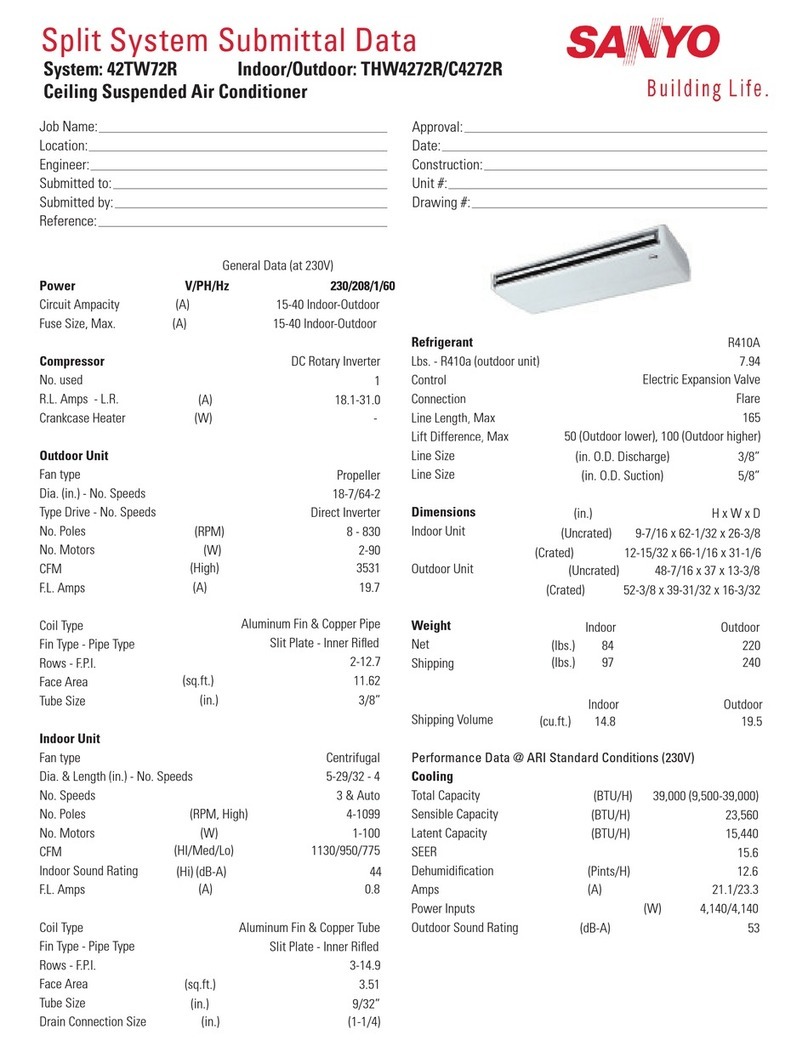
Sanyo
Sanyo 42TW72R Specifications

Mitsubishi Electric
Mitsubishi Electric MSZ-GE71VA operating instructions


