Adec Decade 1011 User manual

Owner's
Guide
Decade
*
1011/1021
Chair
afdec*
85.2635.00
Products
List
Table
of
Contents
Warranty
Information
Serial
Number
_
Model
Number
_
Date
Purchased_
Date
of
Service
Model/Description
of
Service
Technician's
Initials
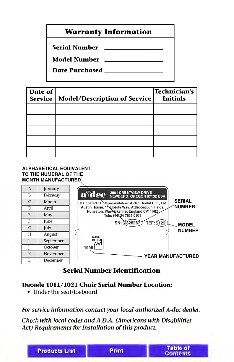
ALPHABETICAL
EQUIVALENT
TO
THE
NUMERAL
OF
THE
MONTH
MANUFACTURED
\
A
January
B
February
c
March
D
April
E
May
F
June
G
July
H
August
I
September
I
October
K
November
L
December
Serial
Number
Identification
Decade
1011/1021
Chair
Serial
N
um
ber
Location:
•
Under
the
seat/toeboard
For
service
information
contact
your
local
authorized
A-dec
dealer.
Check
with
local
codes
and
A.D.A.
(Americans
with
Disabilities
Act)
Requirements
for
Installation
of
this
product.
Products
List
Print
I
Table
of
Contents

Warranty
A-dec
warrants
its
products
and
A-dec/W&H
Synea
handpieces
against
defects
in
material
or
workman¬
ship
for
one
year
from
time
of
delivery.
All
other
handpiece
instrumentation
has
a
warranty
period
of
six
months.
A-dec's
sole
obligation
under
the
warranty
is
to
provide
parts
for
the
repair,
or
at
its
option,
to
provide
the
replacement
product
(excluding
labor).
The
buyer
shall
have
no
other
remedy.
(All
special,
incidental,
and
coincidental
damages
are
excluded.)
Written
notice
of
breach
of
warranty
must
be
given
to
A-dec
within
the
warranty
period.
The
warranty
does
not
cover
damage
resulting
from
improper
installation
or
maintenance,
accident
or
misuse.The
warranty
does
not
cover
damage
resulting
from
the
use
of
cleaning,
disinfecting
or
sterilization
chemicals
and
processes.
The
warranty
also
does
not
cover
light
bulbs.
Failure
to
follow
instructions
provided
in
A-dec's
Operation
and
Maintenance
Instructions
(Owner's
Guide)
may
void
the
warranty.
NO
OTHER
WARRANTIES
AS
TO
MERCHANTABILITY
OR
OTHERWISE
ARE
MADE.
afdec*
All
product
names
used
in
this
document
are
trademarks
or
registered
trademarks
of
their
respective
holders.
Printed
in
U.S.A.
•
Copyright
©
2000
•
All
Rights
Reserved
Products
List
Table
of
Contents
Decade
1011/1021
Chair
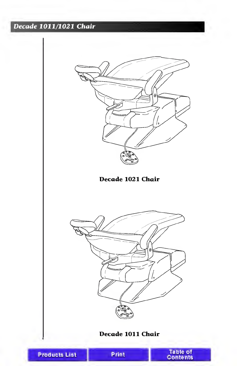
Decade
1021
Chair
Decade
1011
Chair
Products
List
Print
Table
of
Contents

Decade
1011/1021
Chair
CONTENTS
Serial
number
location,
service
information,
and
warranty
information
are
located
on
the
inside
front
cover
and
front
page.
About
Your
Decade
Chair
.
2
Chair
LED.
2
Chair
Stop
Plate.
2
8-Function
Footswitch
.
3
TouchPad
.
3
Programming
the
Chair.5
Folding
Armrest
.
7
Swivel
Brake
.
8
Double-Articulating
Fleadrest
.
9
Positioning
For
Wheel
Chair
.
10
Headrest
Drift
Adjustment
.
11
Left/Right
Conversion
.
12
Care
Instructions
.
14
Upholstery
Replacement
.
15
Backrest
Upholstery
.
15
Seat
Upholstery
.
16
Armrest
Upholstery
.
17
Double-Articulating
Headrest
Upholstery
.
18
Maintenance
.
19
Adjustments
and
Specifications
.
19
Transport
the
Decade
dental
unit.
20
Identification
of
Symbols
.
21
Classification
of
Equipment
(EN
60601-1)
...
21
Products
List
Print
1

Decade
1011/1021
Chair
About
Your
Decade
Chair
Your
Decade
chair
is
an
electronically
controlled,
hydraulically
powered
dental
chair.
Chair
functions
are
controlled
by
the
8-function
footswitch
or
touch
pad
(see
Figure
2
or
2a
on
page
3).
Figure
1.
Lift,
Tilt,
and
Stop
Plate
Chair
LED
The
chair
LED
indicates
the
status
of
the
chair:
ON:
Normal
operation.
SLOW
BLINK:
The
cuspidor
or
stop
plate
limit
switches
have
been
activated.
Remove
any
obstructing
object.
Chair
Stop
Plate
The
chair
stop
plate
(see
Figure
1)
stops
the
chair
immediately
when
any
part
of
it
is
pressed.
Should
anything
inadvertently
become
lodged
under
the
chair,
press
Base
UP
on
the
footswitch
or
touch
pad
to
raise
the
chair
so
the
object
can
be
removed.
As
long
as
pressure
is
applied
to
the
stop
plate,
the
chair
base
will
not
go
down
any
further.
2
Products
List
Print
Table
of
Contents
Decade
1011/1021
Chair
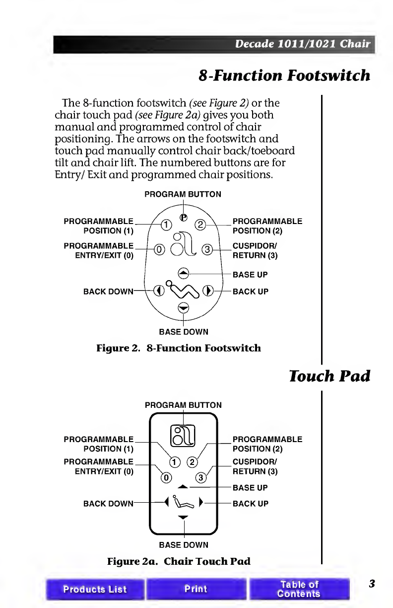
8-Function
Footswitch
The
8-function
footswitch
(see
Figure
2)
or
the
chair
touch
pad
(see
Figure
2a)
gives
you
both
manual
and
programmed
control
of
chair
positioning.
The
arrows
on
the
footswitch
and
touch
pad
manually
control
chair
back/toeboard
tilt
and
chair
lift.
The
numbered
buttons
are
for
Entry/
Exit
and
programmed
chair
positions.
PROGRAM
BUTTON
PROGRAMMABLE
POSITION
(1)
PROGRAMMABLE
ENTRY/EXIT
(0)
BACK
DOWN
BASE
DOWN
PROGRAMMABLE
POSITION
(2)
CUSPIDOR/
RETURN
(3)
BASE
UP
BACK
UP
Figure
2.
8-Function
Footswitch
Touch
Pad
PROGRAM
BUTTON
PROGRAMMABLE
POSITION
(2)
CUSPIDOR/
RETURN
(3)
BASE
UP
BACK
UP
Figure
2a.
Chair
Touch
Pad
Products
List
Print
Table
of
Contents
3

Decade
1011/1021
Chair
Manual
Control
The
Base
Up/Down
(lift)
function
controls
the
chair's
lift,
or
vertical
movement.
To
raise
the
chair,
push
the
up
arrow
on
the
footswitch
or
touch
pad.
To
lower
the
chair,
push
the
down
arrow
on
the
footswitch
or
touch
pad.
Push
the
button
until
the
chair
reaches
the
desired
height,
then
release
it.
The
Back
Up/Down
(tilt)
function
controls
the
chair
back/toeboard
tilt.
To
raise
the
chair
back,
push
the
right
arrow
on
the
footswitch
or
touch
pad.
To
lower
the
chair
back,
push
the
left
arrow
on
the
footswitch
or
touch
pad.
Push
the
button
until
the
chair
back
reaches
the
desired
position,
then
release
it.
Program
Button
The
program
button
(located
on
the
top
middle
of
the
footswitch,
or
in
between
the
arrows
on
the
touch
pad)
is
used
to
save
the
settings
for
Entry/
Exit
(0),
programmable
positions
(1
and
2),
and
Cuspidor/Return
(3).
4
Products
List
Table
of
Contents

Decade
1011/1021
Chair
Programming
the
Chair
NOTE
When
1
or
2
are
pressed
on
the
footswitch
or
touch
pad,
the
chair
base
and
back
go
to
the
programmed
position.
To
stop
the
chair
at
any
point,
press
any
button
on
the
footswitch
(or
press
any
button
on
the
touch
pad).
Programmable
Positions
1
and
2
To
send
the
chair
to
a
programmed
operating
position,
push
either
1
or
2
on
the
footswitch
(press
1
or
2
on
the
touch
pad).
Positions
1
and
2
are
pro¬
grammed
at
the
factory
to
move
the
chair
to
the
same
position.
To
change
a
programmable
position,
find
the
program
button
on
the
footswitch
or
touch
pad
(see
Figures
2
or
2a
on
page
3).
1
.
Using
the
manual
arrows
on
the
footswitch
or
touch
pad,
set
the
chair
to
the
operating
position
that
you
prefer.
2.
Press
and
release
the
program
button.
An
audible
tone
will
be
emitted.
Then,
within
four
seconds,
push
the
button
for
1
or
2
to
store
that
position.
You
will
hear
an
audible
tone
confirming
that
the
programmable
position
function
has
been
reprogrammed.
3.
Check
the
programmed
position
by
manually
moving
the
chair
to
another
position.
Then
push
and
release
the
button
programmed
in
Step
2.
The
chair
should
move
automatically
to
the
position
set
in
Step
1.
Products
List
Table
of
Contents
5

Decade
1011/1021
Chair
Optional
Program
Functions
Position
3
is
factory
set
in
the
Cuspidor/Return
mode.
In
this
mode,
the
chair
back
will
rise
to
a
pre-programmed
upright
position
providing
the
patient
access
to
the
cuspidor.
Pressing
position
3
a
second
time
lowers
the
chair
back
to
its
previous
operating
position.
Position3
may
also
be
used
as
a
third
Pre-Position
or
as
a
last
position
recall.
Contact
an
authorized
A-dec
Dealer
to
have
Position
3
reconfigured
to
a
third
Pre-Postion
or
as
a
last
position
recall.
6
Products
List
Table
of
Contents

Decade
1011/1021
Chair
Entry/
Exit
(0)
To
send
the
chair
to
a
preset
entry/exit
position,
push
the
position
0
button
(see
Figure
2
or
2a
on
page
3).
NOTE
When
pushed,
Entry/
Exit
(0)
will
cause
the
chair
base
and
back
to
go
to
the
preset
entry/exit
position.
To
stop
the
chair
at
any
point,
push
any
button
on
the
footswitch
or
touch
pad.
If
you
want
to
change
the
preset
entry/exit
position,
first
locate
the
program
button
on
the
footswitch
or
touch
pad
(see
Figure
2
or
2a
on
page
3).
1.
Using
the
manual
arrows,
set
the
chair
to
the
desired
patient
entry/exit
position.
2.
Press
and
release
the
program
button.
An
audible
tone
will
be
emitted.
Within
four
seconds,
press
the
Entry/
Exit
(0)
button
on
the
footswitch
or
touch
pad.
An
audible
tone
will
confirm
that
the
chair
has
been
reprogrammed.
3.
Check
the
Entry/
Exit
(0)
function
by
manually
moving
the
chair
to
another
position.
Push
the
Entry/
Exit
(0)
button.
The
chair
will
move
to
the
position
you
set
in
Step
1.
Folding
Armrest
The
armrests
fold
down
and
out
of
the
way
to
facilitate
patient
entry/exit.
When
lifted,
the
armrests
lock
securely
in
place
for
patient
comfort
during
procedures.
To
lower
an
armrest,
press
the
button
on
the
side
of
the
arm.
Lock
the
armrest
by
lifting
it
until
it
locks
in
place.
Products
List
Table
of
Contents
7

Decade
1011/1021
Chair
BUTTON
Figure
4.
Folding
Armrest
Swivel
Brake
When
engaged,
the
chair
swivel
brake
restricts
rotation
of
the
chair.
With
the
brake
released,
you
can
rotate
the
chair
to
any
position
within
approx¬
imately
30°
either
side
of
center.
To
release
the
swivel
brake,
push
the
brake
lever
to
the
right.
To
engage
the
swivel
brake,
push
the
brake
lever
to
the
left.
If
the
chair
swivels
left
or
right
with
the
brake
engaged,
or
if
it
is
difficult
to
move
with
the
brake
disengaged,
the
swivel
brake
tension
must
be
adjusted.
Using
a
3/16-inch
hex
key,
adjust
the
swivel
brake
tension.
Turn
the
adjusting
screw
clockwise
to
increase
brake
friction.
Turn
the
screw
counter¬
clockwise
to
decrease
brake
friction.
8
Products
List
Print
Table
of
Contents
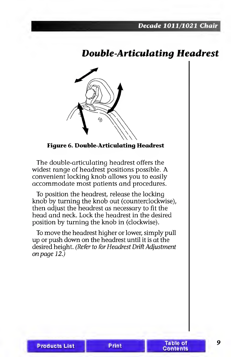
Double-Articulating
Headrest
Figure
6.
Double-Articulating
Headrest
The
double-articulating
headrest
offers
the
widest
range
of
headrest
positions
possible.
A
convenient
locking
knob
allows
you
to
easily
accommodate
most
patients
and
procedures.
To
position
the
headrest,
release
the
locking
knob
by
turning
the
knob
out
(counterclockwise),
then
adjust
the
headrest
as
necessary
to
fit
the
head
and
neck.
Lock
the
headrest
in
the
desired
position
by
turning
the
knob
in
(clockwise).
To
move
the
headrest
higher
or
lower,
simply
pull
up
or
push
down
on
the
headrest
until
it
is
at
the
desired
height.
(Refer
to
for
Headrest
Drift
Adjustment
on
page
12.)
Products
List
Print
Table
of
Contents
9
Decade
1011/1021
Chair
Positioning
For
Wheel
Chair
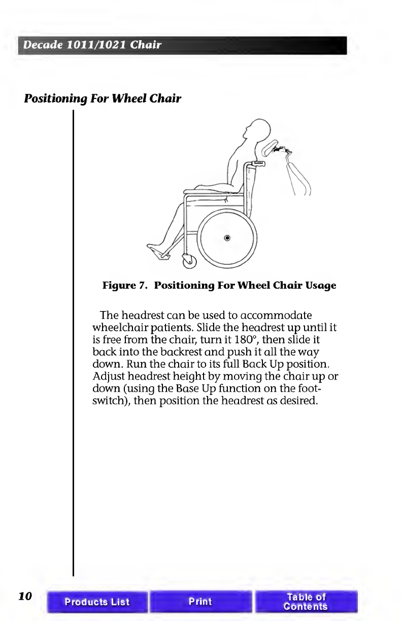
Figure
7.
Positioning
For
Wheel
Chair
Usage
The
headrest
can
be
used
to
accommodate
wheelchair
patients.
Slide
the
headrest
up
until
it
is
free
from
the
chair,
turn
it
180°,
then
slide
it
back
into
the
backrest
and
push
it
all
the
way
down.
Run
the
chair
to
its
full
Back
Up
position.
Adjust
headrest
height
by
moving
the
chair
up
or
down
(using
the
Base
Up
function
on
the
foot-
switch),
then
position
the
headrest
as
desired.
10
Products
List
Table
of
Contents
Decade
1011/1021
Chair
Headrest
Drift
Adjustment
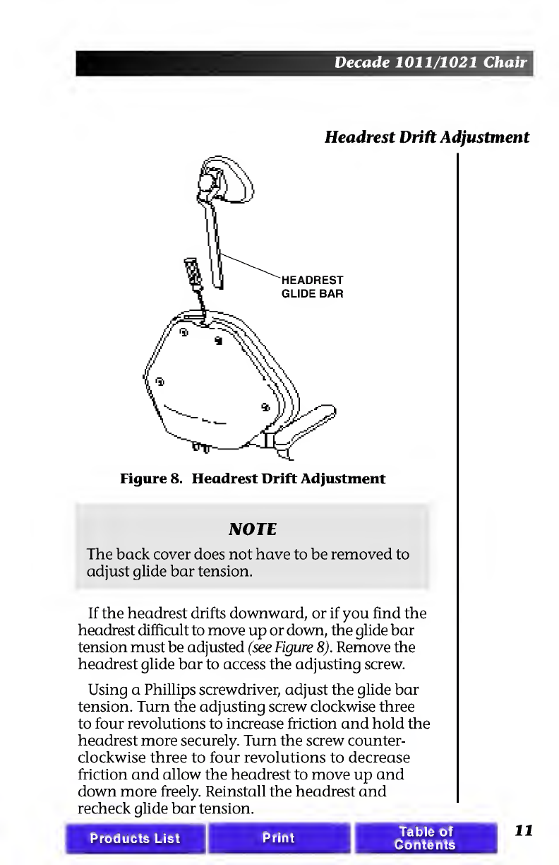
Figure
8.
Headrest
Drift
Adjustment
NOTE
The
back
cover
does
not
have
to
be
removed
to
adjust
glide
bar
tension.
If
the
headrest
drifts
downward,
or
if
you
find
the
headrest
difficult
to
move
up
or
down,
the
glide
bar
tension
must
be
adjusted
(see
Figure
8).
Remove
the
headrest
glide
bar
to
access
the
adjusting
screw.
Using
a
Phillips
screwdriver,
adjust
the
glide
bar
tension.
Turn
the
adjusting
screw
clockwise
three
to
four
revolutions
to
increase
friction
and
hold
the
headrest
more
securely.
Turn
the
screw
counter¬
clockwise
three
to
four
revolutions
to
decrease
friction
and
allow
the
headrest
to
move
up
and
down
more
freely.
Reinstall
the
headrest
and
recheck
glide
bar
tension.
Print
Products
List
Table
of
Contents
Decade
1011/1021
Chair
Left/Right
Conversion
When
combined
with
a
conversion-compatible
A-dec
chair-mounted
handpiece
control
system,
your
Decade
chair
allows
you
to
convert
for
either
left-
or
right-hand
delivery.
If
you
have
a
Radius®
Delivery
System,
go
to
page
15.
1.
Raise
the
chair
back,
then
disconnect
the
chair
from
the
power
source
to
prevent
injury
caused
by
accidental
lowering
of
the
chair.
2.
Remove
the
chair
swivel
brake
cover.
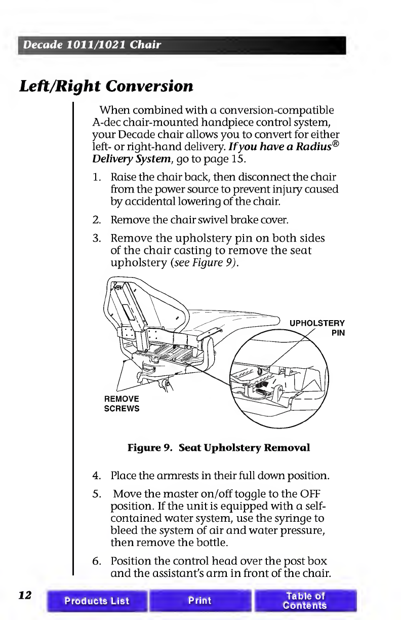
3.
R
emove
the
upholstery
pin
on
both
sides
of
the
chair
casting
to
remove
the
seat
upholstery
(see
Figure
9).
Figure
9.
Seat
Upholstery
Removal
4.
Place
the
armrests
in
their
full
down
position.
5.
Move
the
master
on/off
toggle
to
the
OFF
position.
If
the
unit
is
equipped
with
a
self-
contained
water
system,
use
the
syringe
to
bleed
the
system
of
air
and
water
pressure,
then
remove
the
bottle.
6.
Position
the
control
head
over
the
post
box
and
the
assistant's
arm
in
front
of
the
chair.
12
Products
List
Print
Table
of
Contents
Decade
1011/1021
Chair
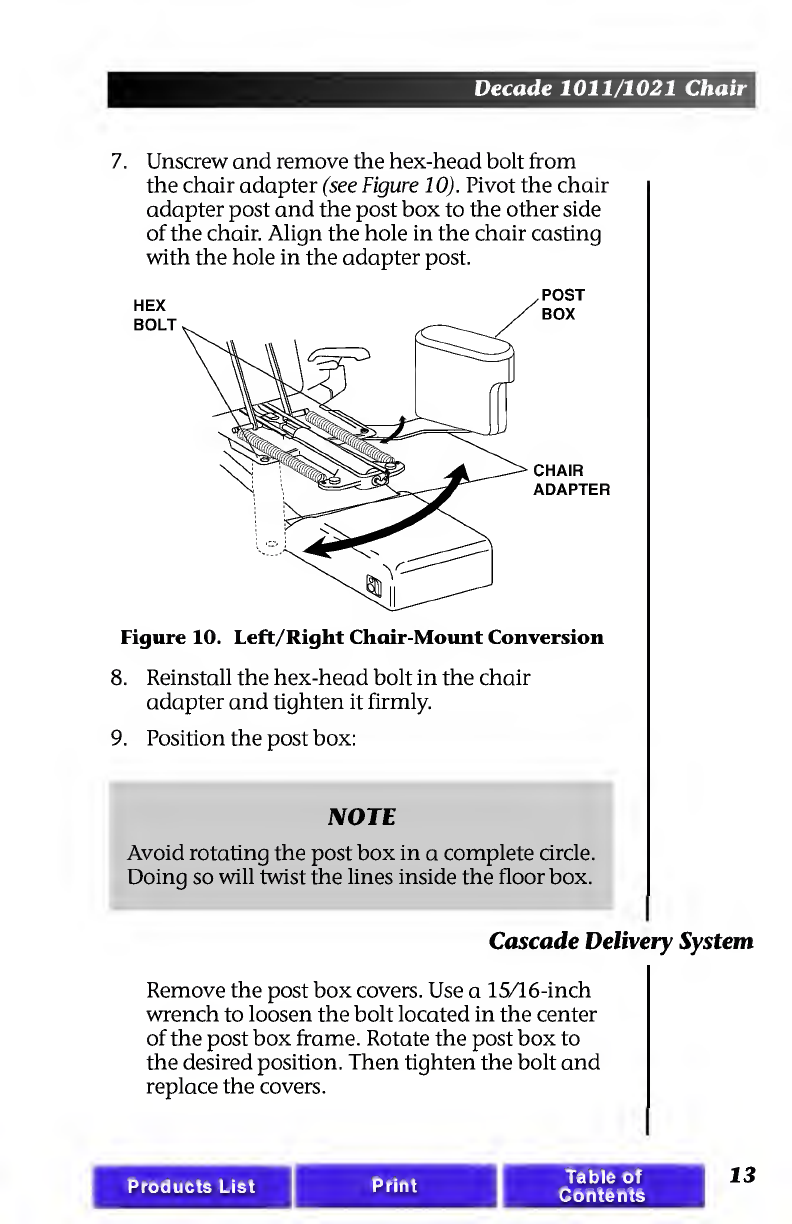
7.
U
nscrew
and
remove
the
hex-head
bolt
from
the
chair
adapter
(see
Figure
10).
Pivot
the
chair
adapter
post
and
the
post
box
to
the
other
side
of
the
chair.
Align
the
hole
in
the
chair
casting
with
the
hole
in
the
adapter
post.
HEX
BOLT
CHAIR
ADAPTER
Figure
10.
Left/Right
Chair-Mount
Conversion
8.
Reinstall
the
hex-head
bolt
in
the
chair
adapter
and
tighten
it
firmly.
9.
Position
the
post
box:
NOTE
Avoid
rotating
the
post
box
in
a
complete
circle.
Doing
so
will
twist
the
lines
inside
the
floor
box.
Cascade
Delivery
System
Remove
the
post
box
covers.
Use
a
15/16-inch
wrench
to
loosen
the
bolt
located
in
the
center
of
the
post
box
frame.
Rotate
the
post
box
to
the
desired
position.
Then
tighten
the
bolt
and
replace
the
covers.
Products
List
Table
of
Contents
13

Decade
1011/1021
Chair
10.
Replace
the
self-contained
water
bottle.
11.
Plug
in
the
chair,
and
turn
the
system
on.
Check
the
post
box
connections
for
leakage
or
pinched
tubing.
12.
Return
the
chair
to
the
entry
position
and
move
the
foot
control
to
the
other
side
of
the
chair.
Radius
Delivery
System
Simply
rotate
the
handpiece
control
and
light
arms
to
the
desired
position.
Care
Instructions
The
unique
Radius
bearing
mount
allows
the
delivery
system
to
rotate
around
the
toeboard
in
one
continuous
motion,
eliminating
the
need
for
tools
or
fine
adjustments.
For
surface
cleaning
and
disinfection
instructions,
refer
to
your
Equipment
Asepsis
Owner's
Guide,
A-dec
Publication
No.
85.0696.00.
14
Products
List
Table
of
Contents

Decade
1011/1021
Chair
Upholstery
Replacement
The
upholstery
on
your
chair
is
installed
in
four
sections:
back,
seat,
headrest,
and
armrests.
Each
section
is
easily
removed
and
replaced.
Backrest
Upholstery
Remove
the
four
screws
securing
the
backrest
cover
and
set
the
cover
and
screws
aside.
Using
a
5/64"
hex
key,
remove
the
four
mounting
screws
that
hold
the
upholstery
to
the
backrest,
then
remove
the
existing
upholstery.
Reverse
this
proce¬
dure
to
replace
the
upholstery.
BACKREST
Products
List
Print
Table
of
Contents
15
Decade
1011/1021
Chair
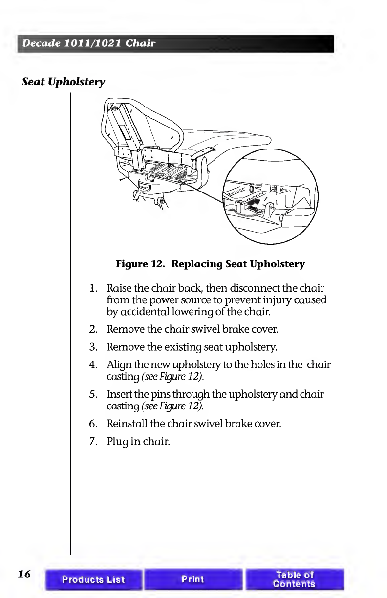
Seat
Upholstery
Figure
12.
Replacing
Seat
Upholstery
1.
Raise
the
chair
back,
then
disconnect
the
chair
from
the
power
source
to
prevent
injury
caused
by
accidental
lowering
of
the
chair.
2.
Remove
the
chair
swivel
brake
cover.
3.
Remove
the
existing
seat
upholstery.
4.
Align
the
new
upholstery
to
the
holes
in
the
chair
casting
(see
Figure
12).
5.
Insert
the
pins
through
the
upholstery
and
chair
casting
(see
Figure
12).
6.
Reinstall
the
chair
swivel
brake
cover.
7.
Plug
in
chair.
16
Products
List
Print
Table
of
Contents
This manual suits for next models
1
Table of contents
Popular Indoor Furnishing manuals by other brands

Atmos
Atmos Chair 21 D operating instructions

rst brands
rst brands Venetia OP-ALSOF88-VEN manual

Cooper Cases
Cooper Cases MEGA instruction manual

Spectrum Industries
Spectrum Industries Esports Shoutcaster Station 37420 Assembly instructions

Portable Bar Company
Portable Bar Company COMPACT BAR Setup guide

Gold Standard Games
Gold Standard Games HOME PRO Assembly instructions

Sanipex
Sanipex BAGNODESIGN BDF-ORO-FUR-GEN installation guide

Furn Mill
Furn Mill Autumn HOCHR00291 Assembly instruction

PHI VILLA
PHI VILLA E02GF-039-BU Use and care guide

New Classic Furniture
New Classic Furniture ANTON U4136 Assembly instructions

modway
modway EEI-1038 manual

True
True ARCA AA WT00 Assembly instructions


