Adesys SVA User manual

MEASURING - ALERTING - CONNECTING
EN
Manual SVA
Version 02-2021

Page 2Manual SVA alarm dialler
Adesys B.V. | Wateringen
Index
1. Introduction 3
1.1. Variants 3
1.2. Features of the SVA-series 3
1.3. Safety criteria 3
1.4. Checking the delivery 3
1.5. Environment 3
1.6. Warranty and repair 3
1.7. Liability 4
1.8. Identication 4
2. Connection 5
2.1. Positioning 5
2.2. Axingandremoval:DINrail 5
2.3. SIM card 5
2.4. Antenna 6
2.5. Power supply 6
2.5.1. SV-20mainsadapterandSV-19DINrailpowersupply 6
2.5.2. Power supply 6
2.6. Reset key 6
2.7. Ethernet 6
2.8. 2G/4G connection 7
2.9. Inputs and outputs 7
3. SV-prog 7
3.1. Installation 7
3.2. Status screen 7
3.3. Call list 7
3.4. I/O 7
3.4.1. Input delay 8
3.4.2. Recovery report (idle) 8
3.4.3. System errors 8
3.5. Connections 8
3.5.1. Checkmyproces.com 8
3.5.2. Own server 8
3.6. System 8
3.6.1. Device 8
3.6.2. Ethernet 8
3.6.3. GSM and mobile data 8
3.6.4. Factory reset 9
4. Noticationprocedure 9
4.1. Noticationmessage 9
4.2. Noticationofstatuschanges 9
4.3. Acceptance SMS 9
4.4. Noticationofmainspowerfailure 9
5. Output switching by SMS 10
6. Importandexportofsettings 10
7. Appendices 11
7.1. Led status indication 11
7.2. Technicalspecications 11

Page 3Manual SVA alarm dialler | Back to Index
Adesys B.V. | Wateringen
1. Introduction
ThismanualcoverstheSVAmoduleequippedwithrmwareversion1.0andhigher.TheSVAisanalarm
dialler and can be used to monitor processes and report alarms via SMS and Email.
1.1. Variants
TheSVAisavailableintwovariants:
• the SVA with digital inputs;
• the SVA with digital inputs and a relay output.
1.2. FeaturesoftheSVA-series
• Checkmyproces.com.
• Congurabledelaytimes.
• Reporting of power failure without acceptance time delay.
• Periodicrestart(reset)oftheSVA(canbeswitchedonando).
• Ethernet interface UTP connection.
• SettingsandSMStextsarepermanentlystoredintheinternalashmemoryoftheSVA.
We recommend that you read the user manual carefully so that you can make optimal use of all SVA
options.
1.3. Safetycriteria
Before using the SVA, there are several criteria that the user should meet.
• TheSVAshouldbeinstalledinacontrolledenvironment(forreasonsofreprevention).
• The SVA should be supplied with power using a SELV-type power supply.
• ExternalEthernetshouldnotbeconnecteddirectlytoanSVA,butshouldbeconnectedviaan
overvoltage protection device.
• To reduce the probability of damage to the equipment, the SVA should be placed in an environment
protectedagainstelectrostaticdischarge(ESD).
• The SVA is intended for use as a modem or alarm dialler. The SVA is not intended for use as part of a
critical safety system in a critical process.
1.4. Checking the delivery
Check the packaging for damage. Contact your supplier immediately if the delivery is found to be
damaged or incomplete upon receipt.
The standard delivery includes:
• SVA module;
• Connection terminals;
• Ethernet cable;
• Quickstart SV-line.
Optional items include:
• Antenna and antenna cable (various models, including vandalism-proof antennas);
• Mainsadapter230VAC/12VDC(itemnumberSV-20).
1.5. Environment
This product contains materials that can harm the environment. For the sake of the environment, if the
product has to be replaced at the end of its service life please do not dispose of it through the household
waste. Please return the device to your supplier or hand it over to a designated depot.
1.6. Warrantyandrepair
AdésysperformsaseriesofextensivetestsoneachSVAbeforedispatch.Adésysusesawarrantyperiod
of 1 year.
Warranty claims are invalidated if:
• Thedefectiscausedbygrossnegligenceorinexpertinstallation;
• Thedevicehasbeenopenedand/orrepairsormodicationshavebeenperformedwithoutthe
permission of Adésys;
• It is found that the serial number has been removed or damaged;
Please get in touch with Adésys customer service if you have any questions regarding the warranty or
repairs.

Page 4Manual SVA alarm dialler | Back to Index
Adesys B.V. | Wateringen
1.7. Liability
Adésys accepts no liability for consequential loss in the event of the stagnation of the alarm. An alarm
dialler does not provide a 100% guarantee against damage, it is merely a tool to prevent damage. You
should therefore discuss the remaining risk with your insurer.
1.8. Identication
Figure 1 Identication SVA
1
2
3
4
5
6
7
8
9
10
1 Reset button
2LEDstatusindicator:generalstatus(on/busy),antennalevel(network),errormessages(error)
3 Antenna connection type SMA female
4 SIM card holder
5 Ethernet connection
6 Information sticker
7 Input/output connection terminals
8 Supply voltage connection terminals
9 Connection sticker
10 DINrailmountingclamp

Page 5Manual SVA alarm dialler | Back to Index
Adesys B.V. | Wateringen
2. Connection
ToconnecttheSVAcorrectly,werecommendusingexclusivelyCamdenCTB922HE/#typeconnectors.
Measurementsmaybeaectedifotherconnectorsareused.
2.1. Positioning
PositiontheSVAwhereitisnotaectedbydirectsunlightorotherheatsources.Choosetheplaceof
installation such that moisture cannot penetrate the device. The SVA can be mounted onto the TS35 rail
without screws. The permitted ambient temperature range for the electronics is -20°C to +50°C.
The transmission power of the SVA’s internal GSM/4G module is higher than that of a standard mobile
phone.Undercertainconditionsthismayaectthefunctioningofsurroundingelectronicequipment.The
eectsdependuponthedistancebetweentheantennaandsurroundingequipment.
2.2. Axingandremoval:DINrail
TheSVAshouldbeaxedtoaDINrailbeforeconnection.
• PuttheSVAontotheDINrailatanangle[1].ItisimportantthattheSVA’sDINrailclipispositionedon
thetopoftheDINrail.
• TilttheSVAtoclipitintoplace[2].Thencheckwhetheritissecurelyseated.
TheSVAisremovedfromaDINrailasfollows.
• PlaceascrewdriverontheundersideoftheDINrailclip[3].Usethisasalever;afterapprox.3mmthe
SVAcanbetiltedtoreleaseitfromtheDINrail.
2.3. SIMcard
The size of the SIM card is the mini SIM card size. If the SIM card has a PIN code, this should be entered in
thesetuptoolSV-prog.TherequiredSIMcardisinstalledasfollows:
• SwitchtheSVAobydisconnectingthesupplyvoltage,thenpressandholdtheresetkeyfor8seconds
toswitchothedialler;
• TheSIMcardholderismadeaccessiblebypressingthebuttonnexttoitusingasharpobject.The
holder is then pushed outwards;
• Place the SIM card in the holder and slide this back into the SVA;
• Reconnect the supply voltage to switch the SVA on.
TheSVAshouldbecompletelyswitchedobeforetheSIMcardisinstalled.FittingorremovingtheSIM
card with the SVA switched on may damage the SIM card.

Page 6Manual SVA alarm dialler | Back to Index
Adesys B.V. | Wateringen
The use of a ‘Prepaid’ SIM card for dialling purposes is strongly discouraged. The mobile network cannot
automatically request the call credit, which means that this can be run down without anyone noticing,
resultinginoutgoingnoticationscomingtoastandstill.
2.4. Antenna
Connect the antenna cable to the SVA’s antenna connection. The antenna plus associated cable can be
obtainedfromAdésys.Theantennashouldbeaxedtoashighapointaspossibletoobtainthebest
possible range.
Afterinstallation,alwayschecktheeldstrengthoftheantennasignal(max.is5ashesoftheyellow
‘network’LED).Noticationofchangesinsignalstrengthwillalwaystakeplaceafteralongdelay(±30
seconds).Takethisintoaccountif,forexample,theantennaismoved.
2.5. Power supply
2.5.1. SV-20mainsadapterandSV-19DINrailpowersupply
TopowertheSVA,a230VAC/24VDCmainsadapterwitharticlenumberSV-20ora100-240VAC/24VDC
DINrailmountingpowersupplywitharticleSV-19canbeorderedasanoptionviathewebshop.
Whenttingtheterminalblocktothepowersupplycable,ensurethatthepolarityplus(+)andminus(-)is
correct.
Anextrapowersupplyfuseisnotnecessaryhere.
IftheSVAisnotsuppliedwithpowerusingtheabove-mentionedmainsadapterorDINrailpowersupply,
the connection regulations in the section below apply.
2.5.2. Power supply
ConnecttheSVAtoaDCpowersupplyof15to35VDC(atleast8.5W)oratransformerof20to30VAC.
ThepowersupplyinputoftheSVAisnotgalvanicallyisolatedfromtheotherconnections.TheGND
connectionofthepowersupplyconnectorisdirectlyconnectedinternallytotheGNDconnectionofthe
input connector and the COM port.
If the SVA is connected to an application (process controller, PLC, computer, active sensor, etc.) without
galvanic isolation and the SVA is connected to the same power supply, there is a real chance of earth loops
and/or short circuits in this power supply.
2.6. Reset key
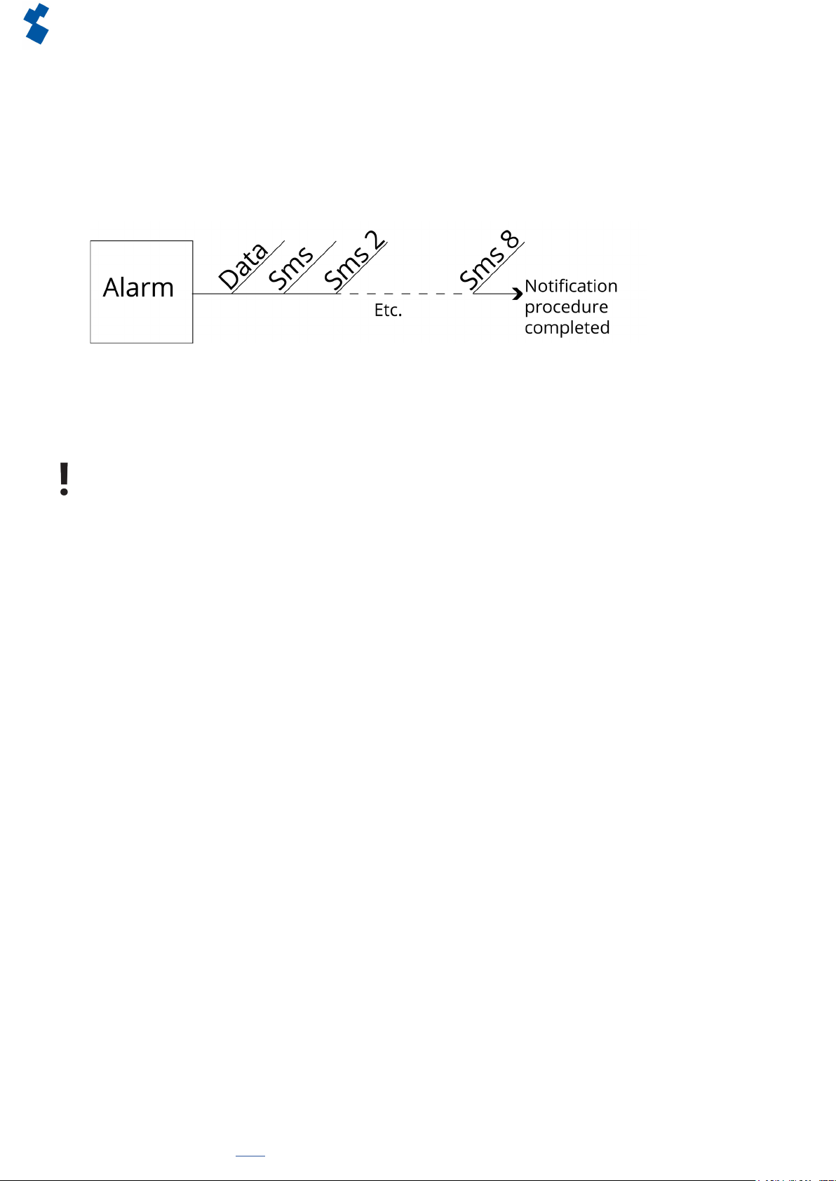
Theresetkeyhasfourfunctions:rstofall,itisusedtointerruptthealarm.Pressingthisbrieyendsthe
currentnotication;theSMSmessagesthathavenotyetbeensentarenotsent.
A second function of the reset key is to restart the dialler. The dialler can be restarted by holding this key
down for a period of 8 seconds. This only occurs if a power supply is connected.
Ifnopowersupplyisconnected,theresetkeyfunctionsasanobutton.Holdingthekeydownfora
periodof8secondsswitchesothedialler.
Statuses of inputs will not be stored in a permanent memory. If the supply voltage fails, and the built-in
supercap is entirely discharged, the contents of this memory is lost. If the SVA is restarted manually, this
status will also be reset. When the supply voltage is restored, the SVA behaves as if it is being started up
forthersttime.Thismeansthat:
• After the supply voltage has been restored, only active inputs are reported once again;
• No recovery message will be sent if the status of the input has been recovered during this power failure.
The fourth functionality is for when there is something wrong and there seem to be no connection. By
pushingtheresetkeyforadurationof3seconds,releasingit3secondsanddoingthis3timestheDHCP
willbeenabled.ByenablingtheDHCPitispossibletomakechangeswithSV-prog.
2.7. Ethernet
TheEthernetconnectioncanbeusedforanexternalconnection.ThisissetupintheSVA:seechapter“3.
SV-prog”. By default this is set up to connect to Checkmyproces.com.

Page 7Manual SVA alarm dialler | Back to Index
Adesys B.V. | Wateringen
2.8. 2G/4G connection
To use the SVA with a 2G/4G connection, a SIM card with Internet subscription should be installed in the
SVA. It is important that the correct APN, APN user and APN password are entered, otherwise the SVA will
not be able to connect. This can be entered in SV-prog in the 2G/4G window.
Network locking is possible. By entering a 2 or 4 in the GSM menu at the provider lock, it is possible to lock
the detector to 2G or 4G.
TheSVAdoesnotprovideanoticationifsomethinggoeswrongwiththeAPN.Formoreinformation
about the APN, please contact your provider.
2.9. Inputsandoutputs
It is possible to connect several variants of inputs and outputs to the SVA, such as contact inputs , voltage
inputsDCorarelayoutput.Whenconnectingdierentinputsitisimportanttolookcarefullyatthewiring
diagram. This can be found on the side of the SVA.
3. SV-prog
3.1. Installation
SettinguptheSVAcanbedoneintwoways,thefullyadjustablewayoftheSV-progtoolandalimited
adjustablewayviaRemoteSetup.ForRemoteSetup,section“3.5.1. Checkmyproces.com” can be
consulted.
SV-prog is used to set up the SV series. This program can be downloaded free of charge from the Adésys
website (www.adesys.nl/en/service/downloads).Allsettingswillbestoredintheinternalashmemory.It
is not possible to store the settings on the SIM card!
SV-prog must be installed on your PC before it can be used. Follow the instructions displayed on your
screen during the installation process. As soon as the installation process is complete, start the program
via the shortcut or via the program menu in MS Windows.
Connect the SVA to a power source and connect the SVA to the PC using the Ethernet cable set supplied.
The SVA can be connected to the local network or directly to the PC.
As soon as the SVA has been switched on, the tool will display this in the overview after a few seconds
andtheSVAcanbeconguredbyclickingit.Whensearchdiallersispressed,SV-progshowsallaccessible
diallers.
When SV-prog is not showing any diallers or when the error message ‘No ethernet cable’ is shown. There
isapossibilitythewrongnetworkadapterischosen.ByopeningSV-progandopeningtheconguration
onthetopleftsideitispossibletoadjustthenetworkadapter.
Terms used
ThetermsyouwillencounterinSV-progareexplainedbelow.
3.2. Statusscreen
ThestatusscreenprovidesyouwithinformationontheSVA.ExamplesofthisinformationaretheIMEI
code, the serial number, the MAC address and the current status of the inputs and alarms/errors.
3.3. Calllist
A call list is a group of contacts (SMS or Email) that can be coupled to the input to send an alarm message
or alarm recovery message. One to eight contacts can be programmed into a call list
3.4. I/O
Inputs are displayed in this window. All inputs can be set up separately from one another. Settings can
also be established here for Mains Power Failure and System Errors.
Onecalllistcanbesetupforeachinput.Assoonasaninputbecomesactive,thenoticationprocedure
starts. The associated alarm message is sent to all set telephone numbers one after the other. This is
explainedfurtherintheNoticationProceduresection.

Page 8Manual SVA alarm dialler | Back to Index
Adesys B.V. | Wateringen
3.4.1. Inputdelay
Adelaycanbesetforthestatusnotication(activeandidlemessage)ininputdelay.Thismeansthe
statusnoticationwillnotbesentuntiltheinputhasbeenactivatedordeactivatedforlongerthanthis
period.Themaximumthatcanbesetis‘3600’seconds.
Ifaninputgoesbackintoidlemodeduringthedelaytime,thenoticationproceduredoesnotstart.
3.4.2. Recovery report (idle)
Ifdesired,arecoveryreportSMScanbesentaftertheinputgoesintoidlemode.Thedefaultsettingiso
evenifnothinghasbeenselected.Select‘Yes’toactivatethisnotication.Arecoveryreportwillalwaysbe
senttotheexternalserver.
3.4.3. System errors
VarioussystemerrorscanbedetectedbytheSVA.Noticationscanbesetupindividuallyforeacherror.
Dependingupontheerror,thisisdisplayedintheprogrammingtoolandanoticationissentviaSMS.By
defaultthenoticationofallsystemerrorsviaSMSisswitchedo.
3.5. Connections
Theterm‘connections’isusedtomeantheconnectiontoanexternalserver.WiththeSVAitispossibleto
make a connection to Checkmyproces.com or to a dedicated server.
3.5.1. Checkmyproces.com
Checkmyproces is a server on which the status is displayed via the cloud. After logging in, diallers can
be connected to the account. This connection takes place via the IMEI number. The IMEI number can be
obtained via SV-prog in the status screen and by looking on the side of de dialler.
Remote conguration
It is possible to remotely make changes to the settings of the dialler. This is possible by ethernet and by
4G/GPRS.Forusingremotecongurationitisnecessarytohaveaconstantconnection.Whenusing4G/
GPRSkeepinmindoftheextracost.
Ifthenetworkissecuredbyuseofarewall.Pleasemakethefollowingexceptions.
Dataconnection
URL : http://svx.meetcentrale.nl:80/severa
Protocol : http
Port : 80
System Settings
URL : mqtt.meetcentrale.nl
Protocol : mqtt
Port : 1883
3.5.2. Own server
It is also possible to enter your own server IP instead of Checkmyproces.com. The status is then sent to
thisIPaddress.Theconnectiontoyourownserverismadeviatwopaths.ThemessageissentviaHTTP
POST and the settings via MQTT. For more information please contact Adésys.
3.6. System
In the system section you can change the general SVA settings, enter GSM and mobile data settings or
trigger a factory reset.
3.6.1. Device
Inthiswindowyoucanchangedevice-specicsettingssuchasdevicename,alarmactivetext,alarm
recoverytext,automaticupdates,periodicresetandaperiodicreport.
3.6.2. Ethernet
EthernetcanbesetupwithaDHCPserverorwiththeIP,DNSandgatewayenteredbytheuser.Whenan
erroroccursitispossibletoresettheDHCPbypushingtheresetkeyforadurationof3seconds,releasing
it 3 seconds and doing this 3 times. After which the leds wil show restart sequence.
3.6.3. GSMandmobiledata
Here,theGSMmodulecanbeswitchedo,thePINcodeentered,2G/4Gmobiledataswitchedoand
locked.YouherealsowillndAPNsetup.PleasecontactyourproviderfortheAPNsettings.

Page 9Manual SVA alarm dialler | Back to Index
Adesys B.V. | Wateringen
3.6.4. Factoryreset
By performing a factory reset all settings will be lost and a reset to the default settings will be prompted.
4. Noticationprocedure
Thenoticationprocedurestartsintheeventofastatuschangeorerror.Ifsetup,theSVAwillrst
establishadataconnectionandsenddata,andthensendtheassociatednoticationmessagetotherst
contactonthecalllistthathasbeensetup.Afterthenoticationmessagehasbeensent,theSVAwaits
foranacceptanceSMS.Thisiscalledtheacceptanceperiod.Duringthisperiod,theuserisrequiredto
sendanSMSbacktotheSVAtoensurethatthenoticationprocedureisended.Ifthisdoesnotoccur,the
nextcontactfromthecalllistwillreceiveanSMS.
4.1. Noticationmessage
AnSMSalarmmessageisstructuresasfollows:device name | input name | status.
• Device name:containsatextchosenbytheuser.Thiscanbesetupinthesystemmenu.
• Input name:containsatextchosenbytheuser,whichiscoupledtotheinputchannel.Thiscanbeset
up in the I/O menu for the relevant input.
SystemerrorssuchastheEtherneterrorandthe‘nonumberscoupled’errorhaveaxedtext(inEnglish)
thatcannotbechanged.Forexample,EthernetfailureusesEthernetfault.
• Status:showswhetheraninputchannelisActiveorIdle.Activeandrecoverytextscanbesetupinthe
system menu.
Email
ThisisusedifanEmailaddressisenteredinthecalllist.Intheeventofanotication,thediallerrst
sendsamessagetoCheckmyprocesviahttpost,whereuponCheckmyprocesconvertsthenotication
into an Email message and sends this to the Email address that has been entered. The structure of the
message is the same as the SMS.
4.2. Noticationofstatuschanges
Afterinputchannel1hasbeenactivated,thefollowingcanbeobserved:
• ThegreenLED(on/busy)ashes1xtoindicatethatinputchannel1isactive;
• Afterafewseconds,thegreenLED(on/busy)ashesfastertoindicatethattheSMSmessageisbeing
sent;
• ThegreenLED(on/busy)againashes1x.TheSMSmessagehasbeensent;
• ThenoticationmessageappearsonthemobilephonetowhichtheSMSmessagehasbeensent;this
messagecanbestructuredasfollows:LOCATION PUMP FAULT Active;
• ThegreenLED(on/busy) continues to show the status of the input until this ceases to be active;
• Iftheinputreturnstoidlemodeandarecoveryreporthasbeensetup,thenoticationmessagewillbe
structuredasfollows:LOCATION PUMP FAULT Idle.
4.3. AcceptanceSMS
After receiving the alarm message, an acceptance SMS should be sent back. The content of this message
does not matter as the SVA uses number recognition to accept the SMS.
4.4. Noticationofmainspowerfailure
The SVA is equipped with a supercap. This gives the dialler the option of sending a few messages in the
eventofapowerfailure.Theassociatednoticationmessageissenttotherstnumberinthecalllist
linkedtothemainspowerfailure.Anysetacceptancetimeisignored.Thismeansthatsucientpoweris
presentinthepowercapstoexecutethereports.
Afterthepowerfails,thefollowingcanbeobserved:
• TheredLED(error)ashes5xtoindicatethatthesupplyvoltagehasbeenlost;
• Afterafewseconds,thegreenLED(on/busy)ashesfastertoindicatethattheSMSmessageisbeing
sent;
• ThegreenLED(on/busy) remains on. The SMS message has been sent;
Figure 2 Notication procedure

Page 10Manual SVA alarm dialler | Back to Index
Adesys B.V. | Wateringen
• ThenoticationappearsonthemobilephonetowhichtheSMSmessagehasbeensent;thismessage
canbestructuredasfollows:LOCATION powerfailure Active;
• TheredLED(error)continuestoshowthestatusofthemainspowerfailureuntilthishasbeen
recovered.
Amainspowerfailuremessagealwaystakespriorityoveranongoingnoticationofastatuschange.After
noticationofthemainspowerfailure,anyinterruptednoticationcanberestarted.Noticationofstatus
changesthathavenotyetbeennotiedthencontinues.ThispriorityarrangementappliesforbothActive
and Idle.
5. Output switching by SMS
With the SVA, the output channel can be switched by means of an SMS message. The SMS message should
bestructuredasfollows:#<Command><parameter1><parameter2>#
• Command = O (Output).
• Parameter1=A(Active)orI(Idle)orP(switchPulse,default:2secondsactive).
• Parameter2 = I/O number.
The output number is not the same as the relay number. Relay number 1 is output 5.
Figure 3 Connectsticker
ExampleSMSmessagetorelay1:
• Output5active:#OA5#
• Output5Idle:#OI5#
• Output5withdefaultPulse:#OP5#
• Output5with8sPulse:#OP58#
• Output5with20sPulse:#OP520#
6. Importandexportofsettings
ItispossibletoexportviaSV-progsettings:
• for importing to the same type of detector;
• as a backup when settings are changed.
Whenimportingtoanotherdetectoritisimportantthatitmeetsthefollowingcriteria:
• thedetectorisofthesametype:SVA2000ItoSVA2000I
• thesettingsareofthesameversion:
• 1.3.7 and lower contains version 2
• 1.4.1 and higher contains version 3
• 1.5.0 and higher contains version 4
• 1.6.0 and higher contains version 5

Page 11Manual SVA alarm dialler | Back to Index
Adesys B.V. | Wateringen
7. Appendices
7.1. Ledstatusindication
Number of ashes for error (red)
1x Problem with GSM module
2x No SIM card detected
3x Incorrect pin code
4x PUK code necessary
5x Power failure
6x No SMS central number / no antenna level
7x No telephone number coupled to input / 2G/4G connection cannot be
established / Ethernet error
8x Connectiontoexternalservercannotbeestablished
Number of ashes for network (orange)
O No antenna
Constant Connectedtoexternalserver
1x Antenna level 1% < > 20%
2x Antenna level 21% < > 40%
3x Antenna level 41% < > 60%
4x Antenna level 61% < > 80%
5x Antenna level 81% < > 100%
Faster Establishing connection (clientmode)
Number of ashes for on/busy (green)
O SVAisswitchedo
On SVA is switched on
Faster Starting up / sending message
1x Input 1 active
2x Input 2 active
3x Input 3 active
4x Input 4 active
5x Input 5 active
6x Input 6 active
7x Input 7 active
8x Input 8 active
7.2. Technicalspecications
Systeemeigenschappen
SVA0000-I Typeofdetector:alarm dialler | (Weblogger|modem)
Number of digital inputs
Number of GPIO inputs
Number of PT100 inputs
Number of relay outputs
I=4G variant
Input/output options (diers for each SVA model) No.
Digitalcontactinput(NO/NC) 4 - 8
Digitalvoltageinput(5-24VDC) 4 - 8
Relay outputs 0 - 2
Hardware 4201 4G 4211 4G
Type I/O SVA4002-I SVA2000-I
SVA8000-I
Contact inputs
max.contactresistance
max.Vinlow
0 - 8
1kΩ
1V
0 - 8
1kΩ
0.4V
Digital inputs (5 - 24VDC)
Abs.Vmaxlevel
Vnommax
Vminhoog
Vmaxlaag
4 - 8
30V
24V
2.0V
1.5V
4 - 8
30V
24V
2.5V
2.0V
Inputs are protected against 24VAC. However, they are not suitable for measuring / detecting AC signals in
Voltage / Contact or Digital Input mode.

Page 12Manual SVA alarm dialler | Back to Index
Adesys B.V. | Wateringen
Hardware 4201 4G 4211 4G
Relay output
Relay modes (P/NO/NC)
Imaxperoutput
Switchable voltage level
Lifeexpectancy
0 - 2
1A
SELV30VDC/1A(resistive)
1x10⁵operationsat20°C,1Hz
-
Ethernet Type 10Base-T/ 100Base-TX
AutoMDIX Yes
GSM/GPRS/EDGE/
LTE Cat-M1 Mobile network Global-BandFDD-LTE
B1/B2/B3/B4/B5/B8/B12/B13/B17/
B18/B19/B20/B25/B26/B28/B39 (B39
CAT-M1 only)
GSM/GPRS/EDGE850/900/1800/1900
MHz(Quadband)
Antenna connection Connector type SMA female
Power supply Nominal 1-2 Watt (2W whilst the supercap is
charging)
Peak 8.5 Watt / 18 VA (AC)
Imax 0.75A @ Vin= 11.4V
Power supply range 15...35VDC(SELV)
20 ... 30VAC (SELV)
Built-in emergency power supply Supercap (loaded after a few
minutes) so that a power
failure can still be reported
Expectedservicelife
(Calculated MTBF) 88167 hours (=10 years), according to componentcounting method
Enclosure and operating conditions
Enclosure DINrail(TS35)mounting;enclosurereretardantUL94-V0
Dimmensions(WxHxD) 23x95x102 (mm)
Weight 125gr
Operating temperature -20°C ... +50°C
Air humidity 20% - 85% (not condensed)
IP code IP10
Maximumheigth Up to 2000 metres
(above2000metresthemaximumoperating
temperature is reduced by 1.5°C per 300 metres up to
amaximumheigthof4000metres)
Regulations
EMC Emission:EN301489-01V1.9.2&EN301489-03V1.4.1(ClassB)
Immunity:EN301489-01V1.9.2&EN301489-03V1.4.1(ClassA)
Safety (CE) EN 60950-1 (2006) + A11 (2009) + A1 (2010) + A12 (2011) + AC(2011) + A2
(2013)
Alert functions
Number of dialing
numbers 3calllists,eachcontaining8dialingnumberspercalllist,maximumof20
digits per dialing number
Notications SMSmessageortextmessageoverIPIPnetwork

Molenweer 4
2291 NR Wateringen
The Netherlands
+31 174 794022
www.adesys.nl
Visit the SVA product page on the website
Also available in this SV-product line:
SVL Weblogger SVM 4G modem Checkmyprocess.com
Industrial 4G Weblogger for
sending alerts in relation to limit
valuesbeingexceeded.
Industrial 4G modem/sms
alarm dialler for connection to
applicationsintheeld.
Convenient display of current
measured values from
your process.
Version 02-2021
Other Adesys Modem manuals
Popular Modem manuals by other brands

NimbeLink
NimbeLink Skywire LTE NL-SW-LTE-S7 Series Configuring guide

Westermo
Westermo TD-32 B quick guide

Spectrum Technologies
Spectrum Technologies DataScout 3920 product manual

Zoom Telephonics
Zoom Telephonics 56K quick start

Murata
Murata DN-24 series user guide

ERE Wireless
ERE Wireless RADIOMODEM D510-E Series manual

Spark
Spark HG659b user guide

Bausch Datacom
Bausch Datacom Proxima ISDN Lite installation guide

MicroNet
MicroNet SP3008UB Quick installation guide

AirLink Communications
AirLink Communications Raven GPRS user guide

Arris
Arris Touchstone CM8200 Setup guide

Best Data Products
Best Data Products DSL542EU user manual