Adimec Q-12 CoaXPress Series User manual
OPERATING AND USER MANUAL
________________________________________________________________________________________________________________
Operating and user manual
Q-12 CoaXPress series
rev2.1
OPERATING AND USER MANUAL Q-12 CoaXPress series
________________________________________________________________________________________________________________
_________________________________________________________________________________________
Adimec 2
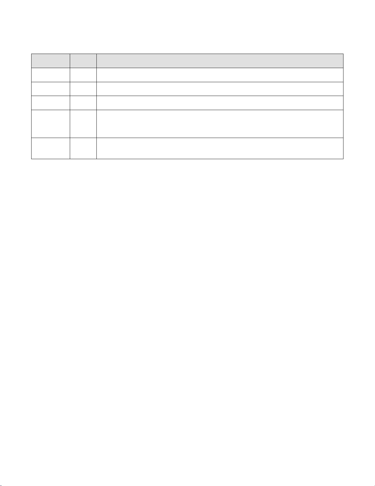
REVISION HISTORY
Revision
Page
Description of revision
2.0
-
Complete revision from the 1.x revision to include the Q-12A180 CXP issue 2.0 camera.
2.1
2
Revision history added.
28
Added remark about defect pixels and max frame rate in binned mode.
58/59
Added section 7.17.23 How to transfer a low frequency flat field calibration set from one
camera to another one. Sections 7.17.24 to 7.17.27 have been updated to describe the
functionality better.
68
Added APPENDIX B: C++ Example, transfer an LF FF calibration set.

OPERATING AND USER MANUAL Q-12 CoaXPress series
________________________________________________________________________________________________________________
_________________________________________________________________________________________
Adimec 3
ABOUT ADIMEC
Adimec designs, manufactures, and markets high performance industrial cameras for equipment manufacturers
in:
•Machine Vision
•Healthcare
•Global Security
Our high resolution cameras offer a unique combination of excellence in image quality, speed, and reliability.
With optimized functionality for the needs of specific applications, Adimec cameras exceed general purpose.
Adimec is a reliable partner with a focus on establishing long term relationships through a worldwide network of
highly qualified engineers.
Adimec aligns its roadmap in close cooperation with industry leaders and monitors the market for the latest
technology to continuously provide innovative cameras that enhance our customers' competitiveness. With our
capabilities, modular designs, process control and commitment to partnership, we can tailor to the exact solution
required in a short time to market and with low risk.
Adimec Advanced Image Systems B.V.
PO Box 7909
5605 SH Eindhoven
The Netherlands
Phone: +31 (0)40 235 3900
E-mail: SalesEU@adimec.com
Adimec Japan
2-10-3-103, Narimasu, Itabashi-Ku
175-0094 Tokyo, Japan
Phone: +81 (3) 5968 8377
Fax: +81 (3) 5968 8388
E-mail: SalesJP@adimec.com
Adimec USA
130 New Boston Street, Suite 204
Woburn, MA 01801, USA
Phone: +1 (781) 279 0770
Fax: +1 (781) 279 0571
E-mail: SalesUS@adimec.com
Adimec Asia/Pacific
60 Paya Lebar Road
#08-07 Paya Lebar Square
Singapore 409051
Phone: +65 6334 1236
Fax: +65 6334 1436
E-mail: SalesAP@adimec.com

OPERATING AND USER MANUAL Q-12 CoaXPress series
________________________________________________________________________________________________________________
_________________________________________________________________________________________
Adimec 4
TABLE OF CONTENTS
REVISION HISTORY.............................................................................................................................................. 2
ABOUT ADIMEC.................................................................................................................................................... 3
TABLE OF CONTENTS......................................................................................................................................... 4
1INTRODUCTION.............................................................................................................................................. 5
1.1 PRODUCT HIGHLIGHTS........................................................................................................................ 5
1.2 ABOUT THIS MANUAL .......................................................................................................................... 5
1.3 LIST OF FREQUENTLY USED ABBREVIATIONS ........................................................................................ 6
1.4 WASTE ELECTRICAL AND ELECTRONIC EQUIPMENT.............................................................................. 6
1.5 LIABILITY............................................................................................................................................ 7
2SAFETY PRECAUTIONS................................................................................................................................ 8
2.1 CLEANING OF THE CMOS SENSOR...................................................................................................... 8
2.2CAMERA HOUSING.............................................................................................................................. 8
3QUICK START GUIDE .................................................................................................................................. 10
4INTERFACES ................................................................................................................................................ 11
4.1 CONNECTOR OVERVIEW.................................................................................................................... 11
4.2 ELECTRICAL INTERFACES.................................................................................................................. 12
5CONTROL OF THE CAMERA ...................................................................................................................... 16
6FUNCTIONAL DESCRIPTION...................................................................................................................... 18
6.1 BLOCK DIAGRAM............................................................................................................................... 18
7FEATURE REFERENCE............................................................................................................................... 20
7.1 FEATURE DESCRIPTION STRUCTURE.................................................................................................. 20
7.2 REQUIREMENTS FOR CHANGING SETTINGS......................................................................................... 21
7.3 BOOTSTRAP COAXPRESS ................................................................................................................ 22
7.4 DEVICE CONTROL............................................................................................................................. 24
7.5 IMAGE FORMAT CONTROL................................................................................................................. 26
7.6 ACQUISITION CONTROL..................................................................................................................... 32
7.7 COUNTER AND TIMER CONTROL......................................................................................................... 38
7.8 HIGH DYNAMIC RANGE MODE........................................................................................................... 39
7.9 ANALOG CONTROL............................................................................................................................ 41
7.10 SENSOR .......................................................................................................................................... 43
7.11 FACTORY......................................................................................................................................... 44
7.12 LUT CONTROL................................................................................................................................. 44
7.13 TRANSPORT LAYER CONTROL........................................................................................................... 46
7.14 DEFECT PIXEL.................................................................................................................................. 46
7.15 DARK FIELD...................................................................................................................................... 50
7.16 BRIGHT FIELD................................................................................................................................... 51
7.17 LF FF CALIBRATION......................................................................................................................... 53
7.18 USER SET CONTROL ......................................................................................................................... 60
7.19 BAND............................................................................................................................................... 63
APPENDIX A: CMOS SENSOR CLEANING INSTRUCTIONS .......................................................................... 66
APPENDIX B: C++ EXAMPLE, TRANSFER AN LF FF CALIBRATION SET ................................................... 68

OPERATING AND USER MANUAL Q-12 CoaXPress series
________________________________________________________________________________________________________________
_________________________________________________________________________________________
Adimec 5
1 INTRODUCTION
The Quartz CMOS camera described in this manual provides 12 Mpx resolution through a CoaXPress interface.
The sensor has a global shutter architecture, combined with CCD like image quality and reliability. Unlike
competitors who are offering general purpose cameras, our products are developed with the specific needs of
OEMs and their applications in mind.
1.1 Product highlights
•12 Megapixel up to 187 fps
•True Global Shutter CMOS
•Column based DSNU and PRNU corrections
•Low frequency flat field correction (issue 2 only)
•Configurable 1,2 or 4 lane CXP3 - 6 interface
•M12 I/O connector
•CoaXPress V1.1.1 compliant
•CoaXPress V1.0 compatible
1.2 About this manual
This manual describes the Q-12 CoaXPress camera series:
Product name
Issue
Part number
Q-12A180-Fm/CXP-6-1.0
1.0
188160
Q-12A180-Fc/CXP-6-1.0
1.0
188170
Q-12A180-Fm/CXP-6-2.0
2.0
197360
Q-12A180-Fc/CXP-6-2.0
2.0
197370
Camera or issue specific functionality or specifications will be clearly indicated. Especially between issue 1.0 and
issue 2.0 there are significant differences in available functionality.
Practical tips or notes are indicated by the “NOTE:” sign.

OPERATING AND USER MANUAL Q-12 CoaXPress series
________________________________________________________________________________________________________________
_________________________________________________________________________________________
Adimec 6
1.3 List of frequently used abbreviations
Abbreviation
Full expression
ASP
Adimec Service Port
CMOS
Complementary Metal Oxide Semiconductor
CRC
Cyclic Redundancy Check
CXP
CoaXPress
DIN
Deutsches Institut für Normung
DPC
Defect Pixel Correction
DSNU
Dark Signal Non-Uniformities
EC
European Commission
EEC
European Economic Community
ESD
Electro-Static Discharge
GenAPI
GenICam Application Programming Interface
GenICam
Generic Interface for Cameras
GUI
Graphical User Interface
HDR
High Dynamic Range
I/O
Input/Output
JIIA
Japan Industrial Imaging Association
LED
Light Emitting Diode
LF FFC
Low Frequency Flat Field Correction
LUT
Look-up Table
PoCXP
Power over CoaXPress
PRNU
Pixel Response Non-Uniformities
RO
Read Only
ROI
Region of Interest
RW
Read and Write
SFNC
Standard Features Naming Convention
USB
Universal Serial Bus
WEEE
Waste Electrical and Electronic Equipment
WO
Write Only
XML
Extensible Markup Language
1.4 Waste Electrical and Electronic Equipment
With regard to waste electrical and electronic equipment (WEEE), Adimec wishes to follow the Directive
2002/96/EC of the European Parliament and of the Council. The purpose of this Directive is, as a first priority,
the prevention of waste electrical and electronic equipment (WEEE), and in addition, the reuse, recycling and
other forms of recovery of such wastes so as to reduce the disposal of waste. It also seeks to improve the
environmental performance of all operators involved in the life cycle of electrical and electronic equipment, e.g.
producers, distributors and consumers and in particular those operators directly involved in the treatment of
waste electrical and electronic equipment.
Separate collection for electronic equipment in your area is recommended in order to minimize the disposal of
WEEE as unsorted municipal waste and to achieve a high level of separate collection of WEEE.

OPERATING AND USER MANUAL Q-12 CoaXPress series
________________________________________________________________________________________________________________
_________________________________________________________________________________________
Adimec 7
1.5 Liability
Adimec prepares this manual with the greatest care. Please inform Adimec of any inaccuracies or omissions.
Adimec Advanced Image Systems B.V. cannot be held responsible for any technical or typographical errors and
reserves the right to make changes to the product and manuals without prior notice. Adimec Advanced Image
Systems B.V. makes no warranty of any kind with regard to the material contained within this document,
including, but not limited to, the implied warranties of merchantability and fitness for a particular purpose. Adimec
Advanced Image Systems B.V. shall not be liable or responsible for incidental or consequential damages in
connection with the furnishing, performance or use of this material.
All rights reserved. No part of this document may be reproduced, stored in a database or retrieval system, or
published in any other form or way, electronically, mechanically, by print, photo print, microfilm or any other
means without prior written permission from the publisher.
Layout, composing and editorial staff: Adimec Advanced Image Systems B.V.
Illustrations: Adimec Advanced Image Systems B.V.
All correspondence regarding copyrights and translations should be directed to:
Adimec Advanced Image Systems B.V.
PO Box 7909
5605 SH Eindhoven
The Netherlands
Tel: +31 (0)40 235 3900
E-mail: Support@adimec.com
URL: www.adimec.com
© Copyright 2017 Adimec Advanced Image Systems B.V. Eindhoven, The Netherlands.

OPERATING AND USER MANUAL Q-12 CoaXPress series
________________________________________________________________________________________________________________
_________________________________________________________________________________________
Adimec 8
2 SAFETY PRECAUTIONS
NOTE: A CMOS sensor camera is a sensitive device. Please read the following precautions carefully before
continuing unpacking or operating the camera.
NOTE: It is advised to unpack and handle the camera in a clean ESD protected working area.
NOTE: It is advised to read the whole manual before using the camera.
NOTE: Always keep the sensor cap in place as long as no lens is attached.
NOTE: Remove the lens cap just before the lens is screwed on the camera. It is advised to perform this
operation in a clean room or clean bench.
NOTE: Never touch the CMOS sensor surface. The cover glass is easily damaged and the CMOS sensor can
be damaged by ESD.
NOTE: In case the camera is used as a subsystem, it is advised to include the text of this chapter in the
assembly documents of the main system.
2.1 Cleaning of the CMOS sensor
The cleaning of a CMOS sensor is a difficult task with a high risk on permanent damage to the camera.
NOTE: It is advised to prevent cleaning the CMOS sensor as much as possible.
NOTE: Damage of the CMOS sensor due to scratches on the cover glass or ESD is not covered by warranty!
All cameras are checked for cleanliness in our factory before shipment.
Proper handling instructions during system assembly can prevent the CMOS sensor from getting contaminated.
Should cleaning of the CMOS sensor be necessary, please refer to Appendix A: CMOS Sensor cleaning
instructions.
2.2 Camera housing
Thermal interfacing
The actual housing temperature achieved depends on the thermal configuration of the camera and the system in
the end-user application. Provisions as to guarantee maximum housing temperature are therefore a
responsibility of the end-user.
NOTE: The housing temperature should not exceed +50° Celcius.
NOTE: Mount the camera on a substantial (preferably metal) body that can act as a heat sink.
NOTE: Create airflow over the camera e.g. by using a fan.
Cleaning of the camera housing
The camera housing should NEVER be immersed in water or any other fluid. For cleaning, only use a light moist
tissue.

OPERATING AND USER MANUAL Q-12 CoaXPress series
________________________________________________________________________________________________________________
_________________________________________________________________________________________
Adimec 9
Connectors
Take care of the connectors during handling of the camera. Connectors should not be damaged. Prevent the
entry of foreign objects or dirt into the connectors, as this will result in unreliable operation or damage.
Mounting screws
M4 screws should be used with a maximum screw depth of 5 mm. The recommended tightening torque is
188 cNm. Take notice of the maximum length of the screws that may be used for mounting the camera. Using
screws too long can cause damage to the camera.
2.3 Camera repair and Warranty
Repair, modification and replacement of parts shall be done only by Adimec to maintain compliance with the
directive 89/336/EEC electromagnetic compatibility, directive 72/23/EEC low voltage directive and the
international standards.
For repair and warranty claims contact your local dealer or the business offices in your region. The minimum
information we need to know for a repair request or warranty claim are the camera serial number and a detailed
failure description.
In case the camera needs to be returned to investigate the repair options or grant your warranty claim you will
receive a Return Material Authorization (RMA) number. Please use this RMA-number to ship the camera to
Adimec. Cameras without RMA number will be rejected.
Once the camera is arrived at Adimec the camera will be investigated to proof possible repair or grant your
warranty claim. In case of repair the repair costs will be quoted. After your approval of the repair cost camera will
be repaired and returned.

OPERATING AND USER MANUAL Q-12 CoaXPress series
________________________________________________________________________________________________________________
_________________________________________________________________________________________
Adimec 10
3 QUICK START GUIDE
The procedure to obtain the first images from the camera depends to some extend on the frame grabber brand
or type you use.
A general quick start guide is therefore difficult to provide.
NOTE: The Adimec support department has a couple of frame grabbers available. Inform at
support@adimec.com which frame grabber specific quick install guides are available
or can be created.
The general steps to collect your first images are:
1. Mount a lens on the camera.
2. Connect the CXP cables to the camera.
3. Connect the CXP cables to the frame grabber.
4. Start the PC.
5. Go through the frame grabber specific procedure to configure your frame grabber. Some frame grabbers
will automatically identify the camera while for others the right configuration file has to be loaded.
6. Use the capture software supplied by your frame grabber manufacturer to start acquiring images.
For a correct configuration in step 5, the factory default settings might be required. The relevant parameters are
listed in Table 3-1.
Table 3-1: Factory default settings for the Q-12 CoaXPress camera series.
Parameter
Value
Revision
1.1.1
ConnectionConfig
CXP3_X1
ConnectionConfigDefault
CXP6_X4
PixelFormat (mono)
Mono10
PixelFormat (bayer)
BayerGB10
AcquisitionMode
Continuous
ExposureMode
Timed
NOTE: Discovery always occurs on CXP3_X1. Most frame grabbers will change the ConnectionConfig feature
automatically to the ConnectionConfigDefault value after discovery.
OPERATING AND USER MANUAL Q-12 CoaXPress series
________________________________________________________________________________________________________________
_________________________________________________________________________________________
Adimec 11
4 INTERFACES
In this chapter the electrical interfaces as well as the optical interface are described.
4.1 Connector overview
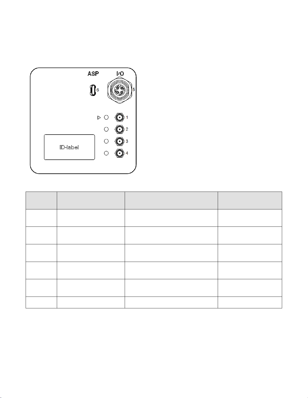
Figure 4-1: Camera back overview.
Table 4-1: Camera connections.
Connector
number
Connector type
Description
Mating connector
1
DIN 1.0/2.3
CXP connection 0 (Master connection)
Video, power, control, triggering
DIN 1.0/2.31
2
DIN 1.0/2.3
CXP connection 1 (Extension, Dual)2
Video
DIN 1.0/2.31
3
DIN 1.0/2.3
CXP connection 2 (Extension, Quad)3
Video
DIN 1.0/2.31
4
DIN 1.0/2.3
CXP connection 3 (Extension, Quad)3
Video
DIN 1.0/2.31
5
Binder M12 type
09-3432-216-04
I/O connector
Binder M12 type
79-3529-13-04
6
Micro USB, type B (Socket)
Adimec Service Port
Micro USB, type B (Plug)
Note:
1Single DIN cables and multi DIN cables supported.
2 Dual: CXP connection 0, 1 are used.
3Quad: CXP connection 0, 1, 2, 3 are used.

OPERATING AND USER MANUAL Q-12 CoaXPress series
________________________________________________________________________________________________________________
_________________________________________________________________________________________
Adimec 12
4.2 Electrical interfaces
4.2.1 Power and CoaXPress connectors
The CoaXPress interface supports communication in two directions. Power, control data and trigger signals are
transferred from the frame grabber to the camera and video data is transferred from the camera to the frame
grabber. The function of each connector is listed in Table 4-1. The CXP configurations that are supported by the
camera are listed in Table 4-2.
Table 4-2: The supported CXP configurations.
Compliance Labeling
Max Bit Rate
per Coax
Nr. connected
Cables
Maximum cable length
(Belden 1694A)
CXP-3 DIN 1
3.125 Gb/s
1
105 m
CXP-3 DIN 2
3.125 Gb/s
2
105 m
CXP-3 DIN 4
3.125 Gb/s
4
105 m
CXP-6 DIN 1
6.250 Gb/s
1
45 m
CXP-6 DIN 2
6.250 Gb/s
2
45 m
CXP-6 DIN 4
6.250 Gb/s
4
45 m
NOTE: Always connect CXP connector 0 as it supplies the camera with power according to the Power over
CoaXPress standard (PoCXP, max 13W).
NOTE: CXP connector 0 is identified by the triangular arrow symbol on the camera housing.
For a complete description of the CoaXPress interface standard please refer to the CoaXPress specification that
can be downloaded from http://jiia.org/en.
OPERATING AND USER MANUAL Q-12 CoaXPress series
________________________________________________________________________________________________________________
_________________________________________________________________________________________
Adimec 13
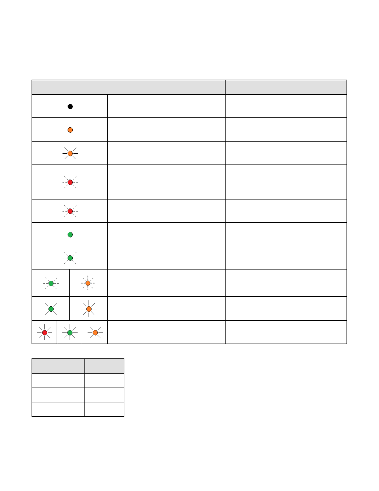
4.2.2 CoaXPress status LEDs
Next to the CoaXPress connector a multi-color LED status indicator is present. The meaning for each LED
indication is shown in Table 4-3, while Table 4-4 lists the frequencies of the fast and slow flashes.
Table 4-3: The meaning of the LED status indicator explained.
LED indication
Camera / interface status
Off No power
Solid orange System booting
Slow pulse orange Device / Host connected, waiting for event
(e.g. trigger, exposure pulse)
500 ms red pulse. In case of multiple
errors, there shall be at least two green
fast flash pulses before the next error is
indicated.
Error during data transfer (e.g. CRC error,
single bit error detected)
Fast flash red System error (e.g. internal error)
Solid green Device / Host connected, but no data
being transferred
Fast flash green Device / Host connected, data being
transferred
Fast flash alternate green / orange.
Shown for a minimum of 1 s even if the
connection detection is faster
Connection detection in progress, PoCXP
active
Slow flash alternate green / orange Connection test packets being sent
Slow flash alternate red / green / orange Compliance test mode enabled
Table 4-4: LED indicator flash frequency
Flash indication
Frequency
Fast flash
12.5 Hz
Slow flash
0.5 Hz
Slow pulse
1 Hz
OPERATING AND USER MANUAL Q-12 CoaXPress series
________________________________________________________________________________________________________________
_________________________________________________________________________________________
Adimec 14
4.2.3 Adimec Service Port
The Adimec Service Port (ASP) interface is available for firmware uploads to the camera.
USB driver XR21x141x is required to support communication via the ASP port.
The USB connection will be available as a virtual COM port.
4.2.4 I/O Connector
A trigger input and flash strobe output are available at the I/O connector. The input and output are galvanic
isolated from the internal camera electronics by means of an optocoupler (Avago ACPL-M50L).
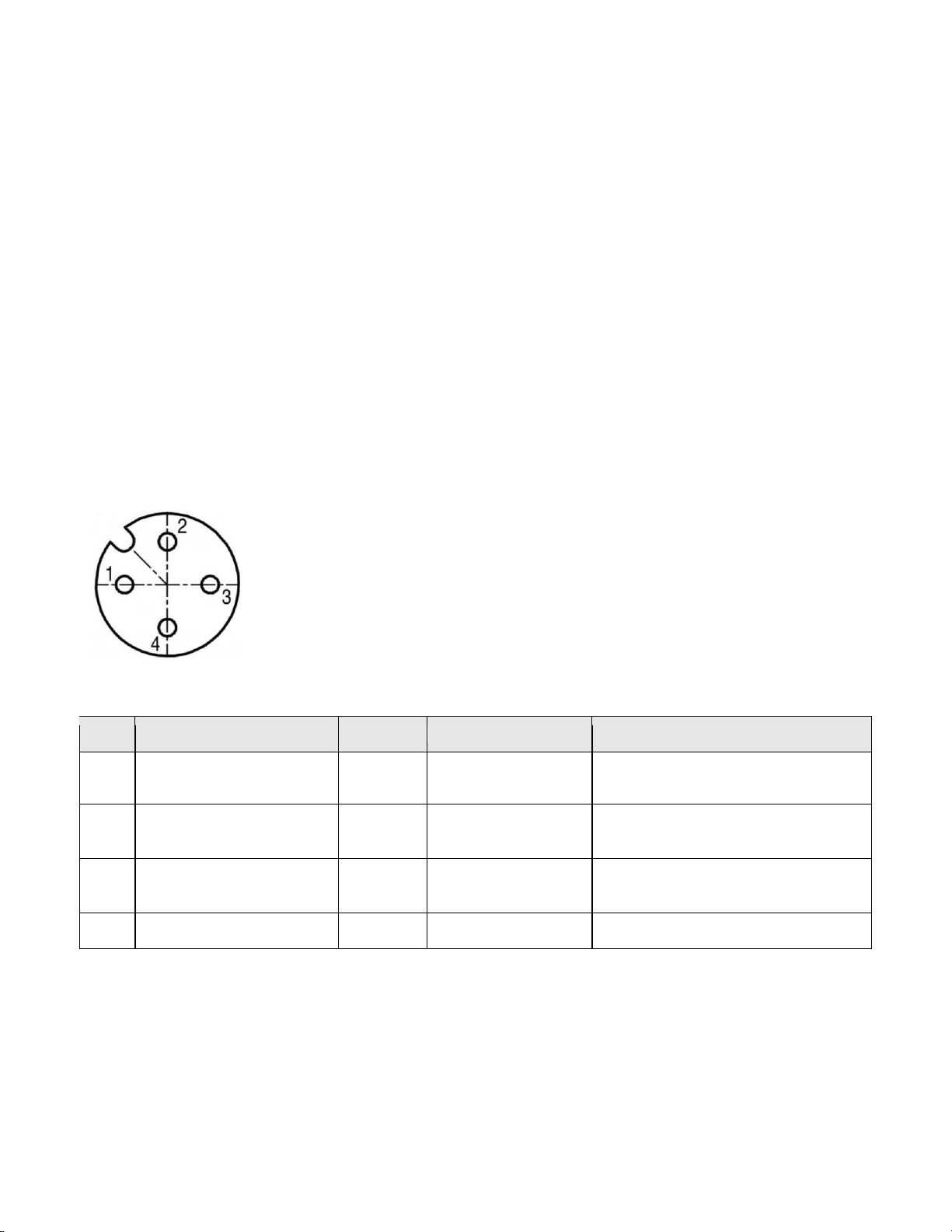
The connector layout is shown in Figure 4-2 with the pin description in Table 4-5.
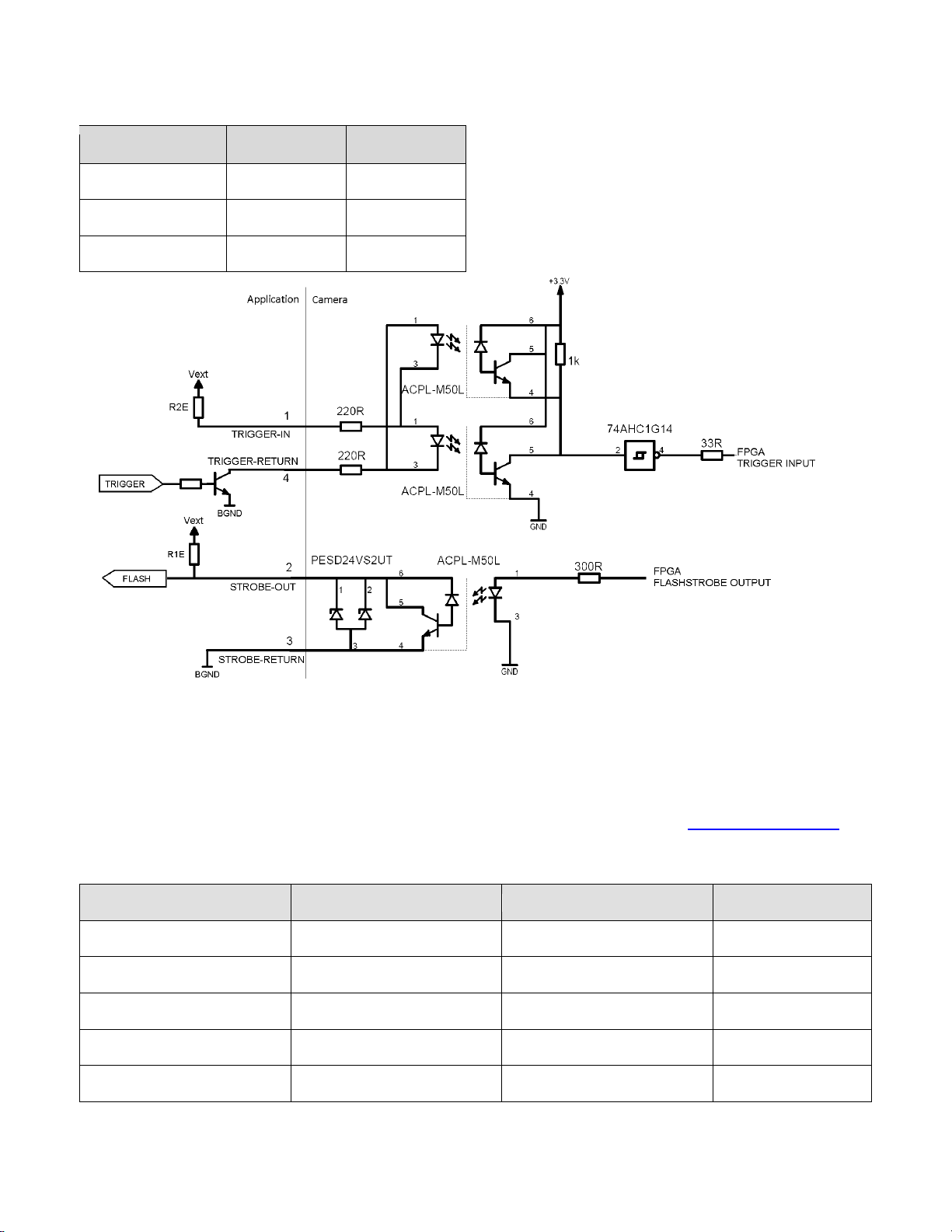
Table 4-6 lists the recommended resistor values to be used in the termination circuitry to achieve the
recommended currents. In Figure 4-3 the recommended termination circuitry is shown.
NOTE: Opto-couplers require a certain response time to turn on or to turn off, i.e. to switch from the non-
conductive state to the conductive state or the other way around. This response time depends on the used
electronic circuit. For the “trigger in” it can be as short as < 0.5 µs. For the “flash strobe out” it can be as short as
< 2 µs. In practice this response time means that when a trigger is applied there will be a delay between the
rising edge of the trigger and the reaction of the camera.
Figure 4-2: Female I/O connector layout viewed from the backside of the camera
Table 4-5: Connector pinning
Pin
Signal name
Type
Level
Description
1
Trigger in
Input
10..20 mA (10 mA
recommended)
Anode of opto-coupler
*
2
Flash strobe out
Output
2.5 mA
Recommended
Open collector of opto-coupler photo
transistor.
3
Flash strobe return
Output
Isolated gnd
Emitter of opto-coupler photo
transistor.
4
Trigger return
Input
Isolated gnd
Cathode of opto-coupler
*serial resistors 2x 220 Ω inside camera.
OPERATING AND USER MANUAL Q-12 CoaXPress series
________________________________________________________________________________________________________________
_________________________________________________________________________________________
Adimec 15
Table 4-6: Recommended resistor values
Vext [V]
R1E ext [Ω]
R2E ext [Ω]
3.3
1000
Do not apply
5.0
2000
0
12
4700
470
Figure 4-3: Recommended terminations strobe output and trigger input
4.2.5 Lensmount overview
The Q-12 camera series can be supplied with various optical interfaces. The available interfaces are listed in
Table 4-7. Other interfaces might be possible as well by using converters. Inform at support@adimec.com for
the possibilities if your interface is not listed in Table 4-7.
Table 4-7: Lensmount overview
Interface
Adjustable
Product name
Product code
M42
No
LENSMOUNT-M42-60
191540
T2
Yes
LENSMOUNT-T2-60
189080
Fn
No
LENSMOUNT-Fn-60
187490
TFLII
Yes
LENSMOUNT-TFLII-60
189590
TFLII
No
LENSMOUNT-TFLII-60
188230

OPERATING AND USER MANUAL Q-12 CoaXPress series
________________________________________________________________________________________________________________
_________________________________________________________________________________________
Adimec 16
5 CONTROL OF THE CAMERA
Access to camera functions and data is provided through the CoaXPress (CXP) protocol. The CoaXPress
interface is GenICam compliant.
GenICam compliant means that an XML is stored in the camera that is used to translate the camera internal
register addresses to the user friendly feature nomenclature as defined by the Standard Features Naming
Convention, SFNC. Basically GenICam is designed to bridge the camera specific register addresses with a
camera and manufacturer independent user interface. The SFNC feature names should be used to operate the
camera.
How to address the SFNC feature names depends on your frame grabber. With CoaXPress frame grabbers a
GenICam Application Programming Interface (GenAPI) is provided. This is a software layer that reads the XML
from the camera and builds a graphical user interface (GUI) to control the camera. The GUI is often refered to as
the GenICam (feature) Browser.
Next to the GUI often a scripting language will be available in which you can use the SFNC naming to program
the camera and frame grabber according to your desired settings.
To illustrate the workflow of CoaXPress we will describe below what will happen if you set the pixel format to 10
bit in a monochrome camera.
When using the GUI:
1. Start the GenICam Browser, The browser will automatically load the XML from the camera and basically
builds a user interface.
2. In the GenICam browser search for the feature called PixelFormat.
3. Change this feature to “Mono10”. Often this can be done by selecting “Mono10” from a drop down list.
When using a scripting language
1. Look up the syntax and language used by your frame grabber.
2. By using the frame grabber syntax and language set the feature PixelFormat to Mono10.
3. Execute the script.
In both cases, for the GUI and for the scripting language, on the background the GenAPI uses the XML to link
the feature name PixelFormat to the camera register address 0x8144. Furthermore it links the feature value
name “Mono10” to a value of 0x1100003. Using the CoaXPress interface, the API will then write a value of
0x1100003 to the camera register 0x8144.
Note: The above mentioned register addresses and values are only for illustrational purposes. The exact
addresses in your camera might be different.
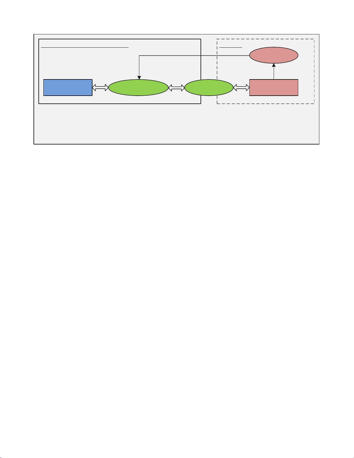
The above described communication protocol is schematically shown in Figure 5-1.
OPERATING AND USER MANUAL Q-12 CoaXPress series
________________________________________________________________________________________________________________
_________________________________________________________________________________________
Adimec 17
Application CameraGenAPI
Description XML
CoaXPress
Frame grabber manufacturer Adimec
Set PixelFormat to
Mono10
Translate SFNC syntax to
camera specific register
address by using the XML file
Transmit register address
and value according to
CXP protocol
Change setting:
Write value to
register
Command syntax
according to SFNC
PixelFormat = 0x00008144
Mono10 = 0x01100003 Write 0x01100003
to 0x00008144 0x00008144 = 0x01100003
Figure 5-1: Schematic view of the CoaXPress communication protocol.

OPERATING AND USER MANUAL Q-12 CoaXPress series
________________________________________________________________________________________________________________
_________________________________________________________________________________________
Adimec 18
6 FUNCTIONAL DESCRIPTION
This chapter contains a functional description of the Q-12A180 camera. It briefly describes the main functions
and features of the camera using a simplified block diagram. More in-depth explanations on these functions as
well as descriptions on how to control them can be found in the next chapters of this manual.
6.1 Block diagram
The diagram below shows the main functional blocks of the Q-12A180 camera.
Image
Sensor BLC
1Col.
FPNC
Test
Pat.
I/O Trigger-IN
I/O Stobe-OUT
LUT CXP
IF
CXP(0)
CXP(1)
CXP(2)
CXP(3)
Device trigger
Hor.
Mirror Insert
Crossh
Hor.
Crop
Trigger &
Sensor
control
White
Bal. DPC
mono
Gain &
Offset
LF FFC
Proc
LF FFC
Meas
Band
Vert.
Crop
Vert.
Mirror
Binning
234
6 7 8 9 10
11
12
7
2 13 3 14 15 16
17
HDR
5
Figure 6-1: Block diagram of the camera. The dashed blocks are sensor functions. The solid blocks are camera
functions. The functionality in the red blocks is only available in Issue 2 cameras.
1. An AMS CMV12000 sensor is used in this camera.
2. The output image can be mirrored horizontally and vertically.
3. A Region of Interest (ROI) can be defined by using the vertical and horizontal crop functionality. The
camera will only output video information from a programmable rectangular sub frame. This reduces the
amount of data and can increase the frame rate.
Issue 2 only – The increment in width has been reduced from 32 to 16. The increment in OffsetX has
been reduced from 16 to 8. This adjustment allows to enable the black clamp and at the same time
leave them outside the output image with the largest resolution possible.
4. Issue 2 only - The Band function generates a rectangular image from a set of configurable bands.
5. HDR - High Dynamic Range - With this function an optical high dynamic range can be realized by using
the multi slope feature of the sensor.
6. BLC - Black Level Clamp - The Black Level Clamp function clamps the black level per line using the dark
reference columns if this function is enabled.

OPERATING AND USER MANUAL Q-12 CoaXPress series
________________________________________________________________________________________________________________
_________________________________________________________________________________________
Adimec 19
7. Issue 2 only - LF FFC – Low Frequency Flat Field Correction – This functionality can correct for a global
(low frequency) non-uniformity. Such a non-uniformity can be present due to a lighting/lens profile or due
to the micro lenses on the sensor.
8. FPNC - Fixed Pattern Noise Correction - Dark field and bright field column based corrections allows for
correction of column based (high frequency) fixed pattern noise (PRNU and DSNU). Calibration of these
functions can be performed in the field.
9. Color only - White balance: a one push and manual white balance is available to set an individual gain
for the RGB channels.
10. This processing block contains the basic processing steps like digital fine gain and black level offset.
11. For functional testing of the camera and frame grabber chain, a test pattern generator is available. The
test pattern generator can be enabled and disabled on demand.
Issue 2 only – A running diagonal test pattern has been added.
12. DPC – Defect Pixel Correction - The defect pixel correction can be enabled and disabled on demand.
From factory a list is available with the major defect pixels. Defect pixels can be added to or removed
from the list by the user.
13. Issue 2 only - Binning – The camera supports up to 2x2 binning. Horizontal and vertical binning can be
enabled independent from each other.
14. An output look-up table (LUT) is available; this table allows real-time conversion of the video levels from
the processing chain according to a user programmable curve
Issue 2 only - a Gamma curve is available in the camera. Instead of the LUT this Gamma curve can be
used.
15. A crosshair overlay can be enabled. This function can be used for the optical alignment of the optics.
16. CXP IF – CoaXPress Interface - The video data is packed into the CXP format for sending data
according to the CXP protocol. The output resolution can be set to 8 bit or 10 bit by user command. The
output format can be set by user command. Both CXP 1.0 and 1.1.1 formats are supported and can be
configured. Standard the camera is configured for CXP 1.1.1. Contact Adimec if the camera needs to be
configured for CXP 1.0.
17. The acquisition rate and exposure time can be controlled externally via a selectable trigger input or the
camera can operate in Timed mode where the camera generates the timing.
The camera is equipped with a flash strobe output signal on the I/O connector. The active state of the
flash strobe output can be inverted to adapt to the application requirements. The flash strobe output can
be operated in two different modes, which are set through a user command.
•The automatic mode: The flash strobe will become active after the sensor is reset and a configurable
delay time is expired. The strobe will deactivate when the acquisition is completed.
•The programmed mode: Both delay time after a sensor reset as well as the duration of the active
state can be programmed.
The delay time between the sensor reset operation in the active state of the flash strobe, as well as the
duration of the flash strobe if the camera is in programmed strobe timing mode, can be user
programmed.

OPERATING AND USER MANUAL Q-12 CoaXPress series
________________________________________________________________________________________________________________
_________________________________________________________________________________________
Adimec 20
7 FEATURE REFERENCE
7.1 Feature description structure
To clearly explain the camera features the structure as described below is used throughout this chapter.
Section headings indicate the group to which the features belong.
Subsection headings indicate the feature name in bold and the accessibility and visibility in normal font.
For example: 7.5.2 Width | RW | B |
The possible accessibility and visibility values are given in respectively Table 7-1 and Table 7-2.
Table 7-1: Possible values for the accessibility level of a feature.
Accessibility
level Abbreviation Description
Read Only RO Features that only present values to the user
Write Only WO Features that can only be written and do not give any feedback to the user
Read and Write RW Features that both, provide information as well as that they can be used to
control the camera.
Table 7-2: Possible values for the visibility level of a feature.
Visibility level Abbreviation Description
Beginner B Features that should be visible for all users via the GUI and API. The
number of features with “beginner” visibility is limited to all basic features
of the devices so the GUI display is well-arranged and is easy to use.
Expert E Features that require a more in-depth knowledge of the camera
functionality. This is the visibility level for all advanced features in the
cameras.
Guru G Advanced features that might bring the cameras into a state where it will
not work properly anymore if it is set incorrectly for the cameras current
mode of operation. The guru parameters mainly have use in debugging.
Invisible I
This is a special visibility level. It is applied to features that are required for
proper operation of the camera or for specific factory settings. Not all
frame grabbers make these features really invisible to the user. However
Adimec advises to not use these features. For this reason they are not
explained in this manual. The features set to invisible are listed at the end
of this Chapter.
The features will mostly be described in a two column table in which the left column gives the possible
input/output values and the right column a short description of the feature or specific feature value. This general
presentation structure is visualized in below table.
Feature input/output
value
Feature or feature value description
This manual suits for next models
8
Table of contents
Other Adimec Digital Camera manuals


