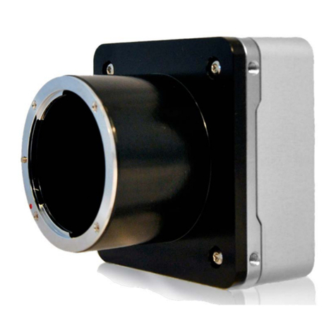
Adimec Camera Link OPAL Series User manual

Operating and user manual
OPAL FAMILY
CAMERA LINK MODELS

OPERATING AND USER MANUAL OPAL FAMILY
2

OPERATING AND USER MANUAL OPAL FAMILY
3
About Adimec
Adimec is the leading supplier of high-performance digital camera modules and camera-lens
assemblies for use in three market segments: machine vision, medical imaging, and applications for
government purposes such as traffic and defense systems. In developing our products as a partner
to major OEMs around the world, we utilize the synergy between these segments to shine in terms of
image quality, speed, dynamic range and reliability.
Adimec is the only company in the market that merges the specific needs of its highly demanding
customers to its technological inventiveness, generating vision solutions of outstanding quality.
The industry-leading standard products provide many times in customer specials, fulfilling the
requirements of your application.
Thanks to this unique approach, Adimec’s solutions add crucial competitive value to our customers’
high-end systems and their applications, as they yield brilliant results to the users of those systems.
The Netherlands-based Holding company has business offices in Europe, the United States, Japan,
and Singapore. For more detailed information about Adimec and our products you can visit our
website www.adimec.com or you can contact your local dealer or the business offices in your region:
Adimec Advanced Image Systems B.V.•
PO Box 7909
5605 SH Eindhoven
The Netherlands
Phone: +31 (40) 2353 920
Fax: +31 (40) 2353 905
E-mail: [email protected]
Adimec Japan•
2-10-3-103, Narimasu, Itabashi-Ku
175-0094 Tokyo, Japan
Phone: +81 (3) 5968 8377
Fax: +81 (3) 5968 8388
E-mail: [email protected]
Adimec Electronic Imaging Inc.•
PO Box 80529
Stoneham, MA 02180,
USA
Phone: +1 (781) 279 0770
Fax: +1 (781) 279 0571
E-mail: [email protected]
Adimec Asia/Pacific•
190 Middle Road, #17-06 Fortune Centre
Singapore 188979
Phone: +65 6334 1236
Fax: +65 6334 1436
E-mail: [email protected]

OPERATING AND USER MANUAL OPAL-CL
4
Contents
1. ABOUT THIS MANUAL 5
1.1 Document applicability 5
1.2 How this guide is organized 5
1.3 Liability 6
2. GENERAL INTRODUCTION 9
2.1 Product highlights 9
2.2 Applications 9
2.3 Camera models 10
2.4 RoHS 10
2.5 Electromagnetic Compatibility (EMC) 10
3. SAFETY INFORMATION 11
3.1 General 11
3.2 Precautions 11
3.3 Safety symbols 11
3.4 Handling 11
4. INSTALLATION 13
4.1 OPAL interface connections 13
4.2 Mechanical 17
4.3 Environmental 18
4.4 Thermal management 19
5. CONTROL OF THE CAMERA 21
5.1 Introduction 21
5.2 Controlling with the Windows Control application 21
5.3 Controlling the camera with the Command Console application 26
5.4 Controlling the camera with your own dedicated software 26
5.5 Command structure 26
6. MANAGING CAMERA SETTINGS 29
6.1 Introduction 29
6.2 Load Power-up defaults and choose power-up set 29
6.3 Change power-up defaults 29
6.4 Obtaining the camera identification string 30
6.5 Obtaining the camera model identification 30
6.6 Obtaining the camera Serial Number 30

OPERATING AND USER MANUAL OPAL-CL
5
6.7 Obtaining the camera build state 31
6.8 User storage 31
7. IMAGE CAPTURING AND VIDEO OUTPUT 33
7.1 Introduction 33
7.2 Selecting Image Acquisition Mode 33
7.3 Used parameters and timing table 34
7.4 Exposure and image output overlap 34
7.5 Image Aquisition in continuous mode 35
7.6 Image Aquisition in normal control mode 37
7.7 Image Acquisition in delayed transfer mode (optional) 38
7.8 Image Acquisition in double transfer mode (optional) 39
7.9 Image Acquisition in double delayed transfer mode (optional) 40
7.10 Image Aquisition in IT defined integration control mode (optional) 41
7.11 Polarity and choice of external triggers 42
7.12 Read-out control 43
7.13 Flash strobe 44
8. IMAGE AND DATA FORMATTING 45
8.1 Introduction 45
8.2 Binning 45
8.3 Region of Interest (optional) 48
8.4 Burst mode (optional) 49
8.5 Vertical remap 51
8.6 Output resolution 52
8.7 Mirror 52
8.8 Digital gain 53
8.9 White Balance (only for color) 53
8.10 Offset (only for color) 54
8.11 Blacklevel (only for monochrome) 54
8.12 Defect pixels 55
8.13 Output LookUp Table. 57
9. SERVICE & MAINTENANCE 59
9.1 Diagnostics 59
9.2 Internal test pattern generator 61
9.3 Information Overlay data format 64
9.4 Cleaning 65

OPERATING AND USER MANUAL OPAL-CL
6
9.5 Maintenance 66
9.6 Repair and modification 66
10. OPTION: AEC/VEM 67
10.1 Introduction 67
10.2 Performance 67
10.3 AEC commands 69
10.4 VEM commands (Monochrome only) 72
10.5 Controlling the AEC setpoint and VEM measurement window 73
11. REFERENCE 75
11.1 Camera Link port configuration 75
11.2 Camera Link video output 76
11.3 Basic serial communication parameters of the camera 77
11.4 Camera Link interface standard 79
11.5 Camera command set overview 80
11.6 Factory Default settings (power-up set 0) 82
12. REVISION HISTORY 83

OPERATING AND USER MANUAL OPAL FAMILY
7
ABOUT THIS MANUAL
About this manual1.
This manual is intended for systems designers and engineers using the Adimec Machine Vision camera
series. This manual provides the necessary information for setting-up, configure and maintaining the
camera. We strongly recommend reading this manual, at least chapters three and four before you
unpack or operate the camera.
Document applicability1.1
This document applies to the cameras mentioned in Table 1.1. This information can be found on the
camera ID label at the bottom of the camera (see figure 1.1 & 1.2) or via the ID? and BS? command.
Elaborate information about camera identification can be found at chapter 6.
MODEL ISSUE
OPAL-1000m/CL 1.0 - 1.2
OPAL-1000c/CL 1.0 - 1.2
OPAL-1600m/CL 1.1
OPAL-1600c/CL 1.2
OPAL-2000m/CL 1.1
OPAL-2000c/CL 1.0
OPAL-4000m/CL 1.0
OPAL-4000c/CL 1.0
OPAL-8000m/CL 1.0
OPAL-8000c/CL 1.0
Applicable camera modelsTable 1.1:
Bottom of the camera with Camera Link interfaceFigure 1.1:
How this guide is organized1.2
First this guide focuses on the electrical and mechanical installation of the camera. This information
should give enough information to properly design in the camera in the application. Follow up by an
explaining of the different commandos for controlling and configuration the camera. Including the
possibilities to control the camera and the commando structure followed by the explanation of every
commando. At the end of this manual reference information is summarized for easy look up of timing
issues and default camera settings.
RoHS
Type
S/N Issue: X.X
: OPAL-XXXXx/x
: XXXXXXXXXXX

OPERATING AND USER MANUAL OPAL FAMILY
8
ABOUT THIS MANUAL
In this manual we use the following standard symbols in the left margin to draw your attention:
WARNING Indicates a hazard that can seriously impair operation.
Do not proceed beyond any of the above notices until you have fully understood
the implications.
Command syntax
¡Return message
NOTE Practical tip or note
(OPTIONAL) Function is not standard. For more information obtaining this function please con-
tact your sales representative.
Liability1.3
Every care has been taken in the preparation of this manual. Please inform your Adimec Business
Office of any inaccuracies or omissions. Adimec Advanced Image Systems B.V. cannot be held
responsible for any technical or typographical errors and reserves the right to make changes to the
product and manuals without prior notice. Adimec Advanced Image Systems B.V. makes no warranty
of any kind with regard to the material contained within this document, including, but not limited to,
the implied warranties of merchantability and fitness for a particular purpose. Adimec Advanced Image
Systems B.V. shall not be liable or responsible for incidental or consequential damages in connection
with the furnishing, performance or use of this material.
Layout, composing and editorial staff: Adimec Advanced Image Systems b.v..
Illustrations: Adimec Advanced Image Systems b.v.
All rights reserved. No part of this document may be reproduced, stored in a database or retrieval
system, or published in any other form or way, electronically, mechanically, by print, photo print,
microfilm or any other means without prior written permission from the publisher.
All correspondence regarding copyrights, translations:
Adimec Advanced Image Systems B.V.
PO Box 7909 Luchthavenweg 91
5605 SH Eindhoven 5657 EA Eindhoven
The Netherlands The Netherlands
Tel: +31 (40) 2353920
Fax: +31 (40) 2353905
URL: www.adimec.com
Publication number: 161585 Manual OPAL FAM rev 1.5
© Copyright 2010 Adimec Advanced Image Systems BV, Eindhoven, The Netherlands.

OPERATING AND USER MANUAL OPAL FAMILY
9

OPERATING AND USER MANUAL OPAL FAMILY
10

OPERATING AND USER MANUAL OPAL FAMILY
11
GENERAL INTRODUCTION
General introduction2.
Congratulations on the purchase of your OPAL camera. Your Adimec camera has been extensively
tested in order to be sure that we delivered a high quality product.
The OPAL camera is designed for Industrial Machine Vision and measurement systems.
The Camera Link digital interface and the size of the camera make electrical and mechanical
interfacing easy. All camera functions are remote controlled. This allows the camera to be optimized
for an integrated application.
Product highlights2.1
The Adimec Machine Vision camera series includes megapixel cameras with the following features:
Platform based product line•
Interline Transfer CCD•
14 bit ADC and channel matching down to sub LSB level•
Extremely low read noise•
Frame buffer for decoupling image acquisition and readout•
Selectable channel remapping in camera•
Horizontal and vertical image flip•
Tight tolerances combined with 100 % factory testing•
Ease of integration through Camera Link standard connection•
Applications2.2
Applications can be found in:
Semiconductor manufacturing•
Electronics manufacturing•
Metrology•
Traffic•

OPERATING AND USER MANUAL OPAL FAMILY
12
GENERAL INTRODUCTION
Camera models2.3
The Adimec Machine Vision camera series are available in several models. Primary differences are the
resolutions and frame speeds.
MODEL RESOLUTION FRAME RATE MONO./COLOR INTERFACE
OPAL-1000m 1024 x 1024 123,1 fps Monochrome Camera Link
OPAL-1000c 1024 x 1024 123,1 fps Color Camera Link
OPAL-1600m 1600 x 1200 69,8 fps Monochrome Camera Link
OPAL-1600c 1600 x 1200 69,8 fps Color Camera Link
OPAL-2000m 1920 x 1080 65,8 fps Monochrome Camera Link
OPAL-2000c 1920 x 1080 65,8 fps Color Camera Link
OPAL-4000m 2336 x 1752 33,5 fps Monochrome Camera Link
OPAL-4000c 2336 x 1752 33,5 fps Color Camera Link
OPAL-8000m 3296 x 2472 17,6 fps Monochrome Camera Link
OPAL-8000c 3296 x 2472 17,6 fps Color Camera Link
Camera models and their main differencesTable 2.1:
RoHS2.4
These products comply with the European RoHS directive, 2002/95/EC
Electromagnetic Compatibility (EMC)2.5
This digital equipment fulfills the requirements for radiated emission according to limit B of
EN61000-6-3, and the requirements for immunity according to EN61000-6-2 residential, commercial,
and light industry.

OPERATING AND USER MANUAL OPAL FAMILY
13
SAFETY INFORMATION
Safety information3.
General3.1
A CCD camera is a sensitive device. In order to ensure your warranty on this product, please read the
following paragraphs scarefully before you continue to unpack and operate the camera.
Read and follow the instructions – All the safety and operating instructions in this manual should•
be read before and be enforced while the camera is operated.
Retain instructions – The safety and operating instructions should be retained for future reference.•
Perceive the warnings – All actions taken should be executed in compliance with the warnings.•
Do not remove the housing of the camera - There are no user-serviceable parts inside. The•
internal electronics may be damaged by touching the components.
Precautions3.2
It is advised to unpack and handle the camera in a clean, ESD protected work area.•
As long as the lens is not mounted, keep the lens cap in place to prevent dust or contamination•
from entering the CCD sensor or filter area.
Remove the lens cap just before the lens is mounted on the camera. It is advised to perform this•
operation in a clean room or at least a clean bench.
Never touch the CCD sensor surface. The cover glass is easily damaged, and the CCD sensor can•
be damaged by ESD (electrostatic discharge).
Safety symbols3.3
The following safety symbols are applicable to and indicated on the camera.
Symbol for “Conformiteé European”
Handling3.4
In order to prevent damage to the camera and to keep the CCD sensor clean, please pay attention to
the following:
Handle the camera with care. Do not abuse the camera. Avoid striking or shaking it. Improper•
handling or storage could damage the camera.
Do not pull or damage the camera cable.•
During camera use, do not wrap the camera unit in any material. This will cause the internal•
temperature of the unit to increase.
Do not operate camera beyond its maximum operating temperature, humidity and power source•
ratings.
Do not expose the camera to the following environmental conditions:•
Wet, moist and/or high humidity areas.-
Direct sunlight.-
High temperature areas.-
In the vicinity of objects that release strong magnetic or electric fields.-
In an electrostatic charged environment.-
Strong vibration.-
Avoid touching the optical surface of the sensor with any object.•
If the optical surface of the sensor needs cleaning, please follow the directions•
in chapter 9.4; ‘Cleaning‘.
The housing is susceptible for scratches. When cleaning the camera, use a soft cloth.•

OPERATING AND USER MANUAL OPAL FAMILY
14
SAFETY INFORMATION

OPERATING AND USER MANUAL OPAL FAMILY
15
INSTALLATION
Installation4.
Camera Link at Base configuration is a universal way of connecting the CL series camera to a
framegrabber and suitable for high speed applications.
The OPAL camera is also available with Coaxpress or GigE Vision interface. It goes beyond the
scope of this manual to elaborate on this. Please contact your local sales representative for further
information.
OPAL interface connections4.1
The camera is equipped with several connectors for the following functions:
Power•
I/O•
Video and Data•
Backside of the cameraFigure 4.1:
Power supply4.1.1.
The camera must be powered by a DC power supply.
All cameras adapt automatically to a wide range of input voltage. There is no galvanic isolation
between input power lines and internal power lines.
For safety, peripheral equipment must be either double isolated or SELF qualified.

OPERATING AND USER MANUAL OPAL FAMILY
16
INSTALLATION
Power connector OPAL camera
Chassis part
Binder series 712 type 09-0403-00-02-
Camera male power connectorFigure 4.2:
PIN FUNCTION
1 10.2 to 27.6 Vdc
2 GND
Power pin configuration for OPAL-1000.Table 4.1:
CAMERA CL MODEL POWER REQUIREMENT
OPAL-1000 < 5 Watt @12 Volt
OPAL-1600 < 6 Watt @12 Volt
OPAL-2000 < 6 Watt @12 Volt
OPAL-4000 < 6 Watt @12 Volt
OPAL-8000 < 6 Watt @12 Volt
Power requirement Camera Link series cameras.Table 4.2:
NOTE: The supply is reverse voltage protected. When applying power to the camera with the wrong
polarity it will not operate, but will not be damaged also.
Mating cable connector:
Binder series 711 type 99-0072-100-02 (straight)-
Binder series 712 type 99-0402-00-02 (straight)-
Binder series 712 type 99-0402-70-02 (90 degrees angle)-
Power cable
All OPAL cameras can be delivered with a power cable (2 meter) as accessory. It is available as
Adimec part no. 102830
WIRE FUNCTION
White Positive (12 - 24 Vdc)
Brown Negative (return)
Shield Mechanical ground
Power pin configurationTable 4.3:
All other wires are not used and should not be connected.
2
1

OPERATING AND USER MANUAL OPAL FAMILY
17
INSTALLATION
I/O Interface4.1.2.
I/O connection
An input for external triggering of the camera is available at the I/O connector.
Also a trigger output signal from the camera to control an external flash light is available at this
connector. The input and output are fully programmable. For reference see par 7.8.
The input and output are galvanic isolated from the internal camera electronics by means of an
optocoupler.
I/O connector
Chassis part:
Binder series 711 type 09-0082-20-04-
Camera female I/O connectorFigure 4.3:
PIN NO. SIGNAL NAME DIRECTION LEVEL AT THE PIN
1 Flash strobe out Output Open collector of optocoupler
2 Trigger in Input 10..20 mA Anode of optocoupler(*)
3 Trigger return Input Isolated gnd Cathode of optocoupler
4 Flash strobe return Output Isolated gnd Emitter of optocoupler
I/O pin configuration.Table 4.4:
(*)serial resistors 2x 220 Ωinside Installationcamera.
Mating cable connector
Binder series 711 type 99-0079-100-04 (straight)-
Binder series 712 type 99-0409-00-04 (straight)-
Binder series 712 type 99-0409-70-04 (90 degrees angle)-
Circuit concept of I/O.Figure 4.4:
3
1
4
2
BGND
Vext
Flash
Vext
Trigger
R1 EXT
R2 EXT
1
4
2
3
Camera Application
Flash strobe out
Trigger in
BGND
220 Ω
220 Ω
I/O Connector

OPERATING AND USER MANUAL OPAL FAMILY
18
INSTALLATION
NOTE: The delay from non-conductive to conductive state of the phototransistor is less than 1.5 μs.
The delay from conductive to non-conductive state of the phototransistor is less than 10 μs.
The recommended termination circuitry is drawn in Figure 4.4.
A current of 2.5 mA is recommended for the Flash output. For the trigger input a current of 10 mA is
recommended. These current recommendations translate to the recommended resistor values in table
4.5.
VEXT [V] R1 EXT [Ω] R2 EXT [Ω]
3.3 1000 Do not apply
5.0 2000 0
12 4700 470
Recommended series resistor for trigger inputTable 4.5:
Video and Data interface4.1.3.
Camera Link
The Camera Link output is designed to connect the camera to a Frame Grabber, in order to transmit
the video and to control the camera settings. It is implemented according to the international Camera
Link specification, described in the Camera Link Interface Standard for Digital Cameras and Frame
Grabbers – Version 1.1 of January 2004.
The maximum theoretical cable length is 7 meter at the rated pixelclock frequency. However, the
maximum attainable Camera Link data transmission distance is subject to cable performance, physical
connection setup, balance, skew, and clock speed, therefore application dependent.
Camera Link Connector
Camera Link connector type: 3M MDR 26-pins.
Female Camera Link connector at the camera.Figure 4.5:
Standard Camera Link cables can be ordered at Adimec.
WARNING: Avoid damage by preventing the entry of foreign objects or dirt to the connectors. The
tightening torque for the retention screws may not exceed 0.29 Nm.
Camera Link ports
The two video outputs TAP-A and TAP-B of the camera are mapped to the Camera Link ports A, B and
C as defined in the Camera Link specification. It is set up as a Camera Link Base configuration and
therefore uses one Camera Link connector.
More information about Camera Link configuration can be found in par 10.1.

OPERATING AND USER MANUAL OPAL FAMILY
19
INSTALLATION
Mechanical4.2
Outline dimensions Camera Link series camera4.2.1.
Camera outline drawing Camera Link camera.Figure 4.6:
Lensmount4.2.2.
4 Torx screws that hold the C-format lensmount (front view of the camera)Figure 4.7:
Upon delivery, the OPAL1000, 1600, 2000 and 4000 cameras are fitted with a C-format lensmount by
means of four screws as indicated in figure 4.7. To prevent damage and contamination of the CCD a
protective plastic cap is placed on the lensmount.
The OPAL8000 camera will be delivered without lensmount.
The OPAL-8000 camera has an 18.13mm (H) x 13.60mm (V) 22.66mm (diag) sized, 4/3” format CCD.
Some applications may requires a lensmount and lens in accordance to the optical format listed.
RoHS
Type
S/N Issue: X.X
: OPAL-XXXXx/x
: XXXXXXXXXXX
12 - 24 Vdc I/O
Camera Link

OPERATING AND USER MANUAL OPAL FAMILY
20
INSTALLATION
Vignetting can be expected with F# values smaller than F4 when using a C-format lensmount.
NOTE: The protective cap may only be removed by pulling it off. Never try to unscrew the protective
cap as this will dissasemble the C-format lensmount.
IN ORDER TO PREVENT DAMAGE TO THE CAMERA AND TO KEEP THE CCD CLEAN, PLEASE
TAKE THE FOLLOWING PRECAUTIONS.
• Always keep the lens cap in place, as long as no lens is attached.
• Pull off the lens cap by just before the lens is screwed on the camera. It is advised to perform this
operation in a clean room or clean bench.
• Never touch the CCD surface. The cover glass is easily damaged, and the CCD can be damaged by
electrostatic discharge (ESD).
Mounting facilities for system integration4.2.3.
In order to provide the facility to integrate the camera into a system, the camera is provided with
mounting holes in the top, bottom and left and right sides of the front. See figure 4.6 & 4.8 for more
details.
WARNING: The length of the thread is 5 mm. The tightening torque for the retention screws may not exceed
1.9 Nm. To prevent damage, do not use bolts which will exceed the length of the tread. See figure 4.8 for
more details
Maximum length of tread.Figure 4.8:
Environmental4.3
EMC/EMI – ESD4.3.1.
The camera complies to the requirements of EN61000-6-2 and EN61000-6-3.
In order to obtain the best performance, the camera and the connected cables should be shielded
from environmental noise sources.
Avoid possible ground loops when integrating in a system. Notice the following circuit diagram.
Simplified diagram of connections in the cameraFigure 4.9:
M4
5 mm
power in
power return
smps
I/O reference
c = < 220 uF R = > 82kΩ
This manual suits for next models
10
Table of contents
Other Adimec Digital Camera manuals
