ADInstruments AD4234 User manual

Manual de Usuario ADInstruments
Comprobador de resistencia a tierra de 4 cables
AD4234

AD Instruments
_____________________________________________________________________
©Copyright Abacanto Digital SA.
Manual de usuario AD4234
2
Contenido
Introducción ………………………………………………………….. 3
Recomendaciones de seguridad ……………………..……….. 4
Características …………………………………………………..…… 5
Especificaciones …………………………………………………….. 6
Diseño del equipo ……………………………………………….…. 7
Métodos de medida ……………………………………………..… 8
Sustitución del fusible ………………………………………..….… 10
Mantenimiento ………………………………………………….……. 11

AD Instruments
_____________________________________________________________________
©Copyright Abacanto Digital SA.
Manual de usuario AD4234
3
Introducción
Este medidor ha sido diseñado y probado de acuerdo con las publicaciones ICE
348 de requisitos de seguridad para aparatos de medición electrónicos, EN
61010-1, EN-61326-1, EN 61557-1 y otras normas de seguridad.

AD Instruments
_____________________________________________________________________
©Copyright Abacanto Digital SA.
Manual de usuario AD4234
4
Recomendaciones de seguridad
Lea cuidadosamente la siguiente información de seguridad antes de intentar
operar o dar servicio al equipo.
Use el equipo sólo como se especifica en este manual. De lo contrario, la
protección proporcionada por el equipo puede verse afectada.
Condiciones nominales medioambientales:
(1).- Uso en interiores y exteriores
(2).- Instalaciones categoría IV 300V
(3).- Grado de polución 2
(4).- Altitud hasta 2.000 metros
(5).- Humedad relativa máxima 80%
(6).- Temperatura de funcionamiento 0º ~ 40º C
Tenga presentes los siguientes símbolos eléctricos internacionales
El medidor está protegido mediante aislamiento reforzado o doble
aislamiento.
¡Precaución! Vea este manual antes de usar el equipo.
¡Cuidado! Riesgo de descarga eléctrica.
Terminal de tierra.
C
E
El equipo cumple con la normas de la Comunidad Europea.

AD Instruments
_____________________________________________________________________
©Copyright Abacanto Digital SA.
Manual de usuario AD4234
5
Características
• Controlado por microprocesador con características avanzadas de seguridad.
• Pantalla LCD.
• Rango automático.
• Comprobación de la resistencia a tierra a 0-20Ω-200 Ω-200 Ω/0-2KΩ.
• Medida de la tensión a tierra: 0 – 300V AC.
• Comprobación automática de la pica C
• Comprobación automática de la pica P
• Comprobación con 2 cables.
• Comprobación con 3 cables.
• Comprobación con 4 cables.
• Apagado automático.
• Retención de datos en pantalla.
• Compacto, robusto y fácil de transportar.
• Normas de seguridad: EN 61010-1 CAT IV 300V
EN 61326-1
EN 61557-1
AD Instruments
_____________________________________________________________________
©Copyright Abacanto Digital SA.
Manual de usuario AD4234
6
Especificaciones
Rangos de Medida
Resistencia a tierra
0
-20, 0-200, 0-2.000, 0-2KΩ
Tensión a tierra
0 –300V AC
Precisión
Resistencia a tierra
±2% de la lectura ± 3 dígitos
Tensión a tierra
±2% de la lectura ± 3 dígitos
Resolución de la
resistencia a tierra
0-20 à0,010
0
-200 à0,10
0
-2000 à10
0-2kΩà0,01KΩ
Temperatura y
humedad
En funcionamiento: 0ºC-50ºC 80% humedad relativa
Almacenado: -1ºC-60ºC 80% humedad relativa
Alimentación
8 x 1,5V (AA)
Dimensiones
250 (L) x 190 (A) x 110 (H) mm
Peso
Aproximadamente 1.430 gr con baterías incluidas
Accesorios
Cables de pruebas (Roja –15m, Negra –10m,
Amarilla
–10m, Verde –5m)
Picas auxiliares de tierra
Maleta de transporte
Baterías
Fusible (0,1A 250V 5x20mm)

AD Instruments
_____________________________________________________________________
©Copyright Abacanto Digital SA.
Manual de usuario AD4234
7
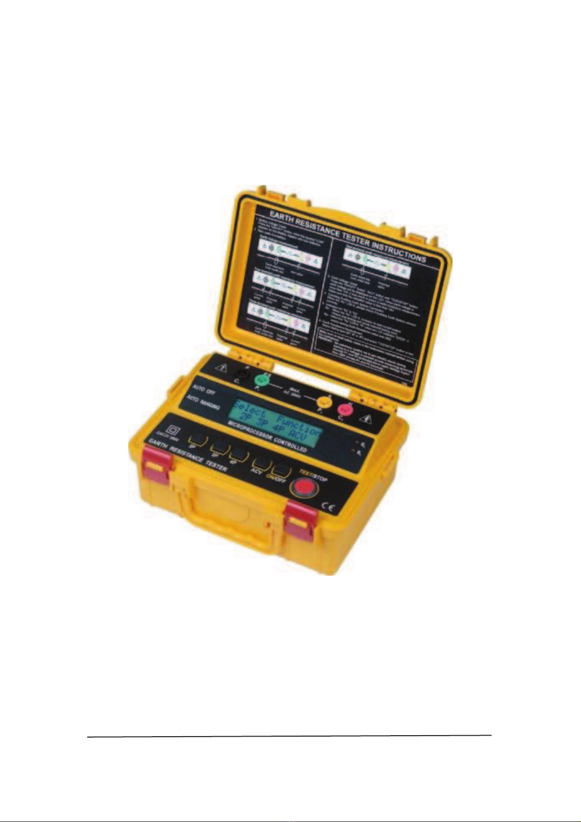
Diseño del equipo
1.- Terminal C1 6.- LED Rc
(Conexión punta de prueba negra) 7.- LED Rp
2.- Terminal P1 8.- Tecla para 2 cables
(Conexión punta de prueba verde) 9.- Tecla para 3 cables
3.- Terminal P2 10.- Tecla para 4 cables
(Conexión punta de prueba amarilla) 11.- Tecla V AC
4.- Terminal C2 12.- Tecla encender/apagar
(Conexión punta de prueba roja) 13.- Tecla TEST/STOP
5.- Pantalla LCD

AD Instruments
_____________________________________________________________________
©Copyright Abacanto Digital SA.
Manual de usuario AD4234
8
Métodos de medida
1.- Comprobación de la tensión de la batería
a.- Antes de hacer una prueba, pulse la tecla “ON/OFF”, cuando aparezca
en la pantalla el mensaje; “Battery Low”, sustituya las baterías por otras
nuevas.
b.- Antes de efectuar una medida, si aparece en la pantalla el mensaje;
“Battery Low”, sustituya las baterías por otras nuevas.
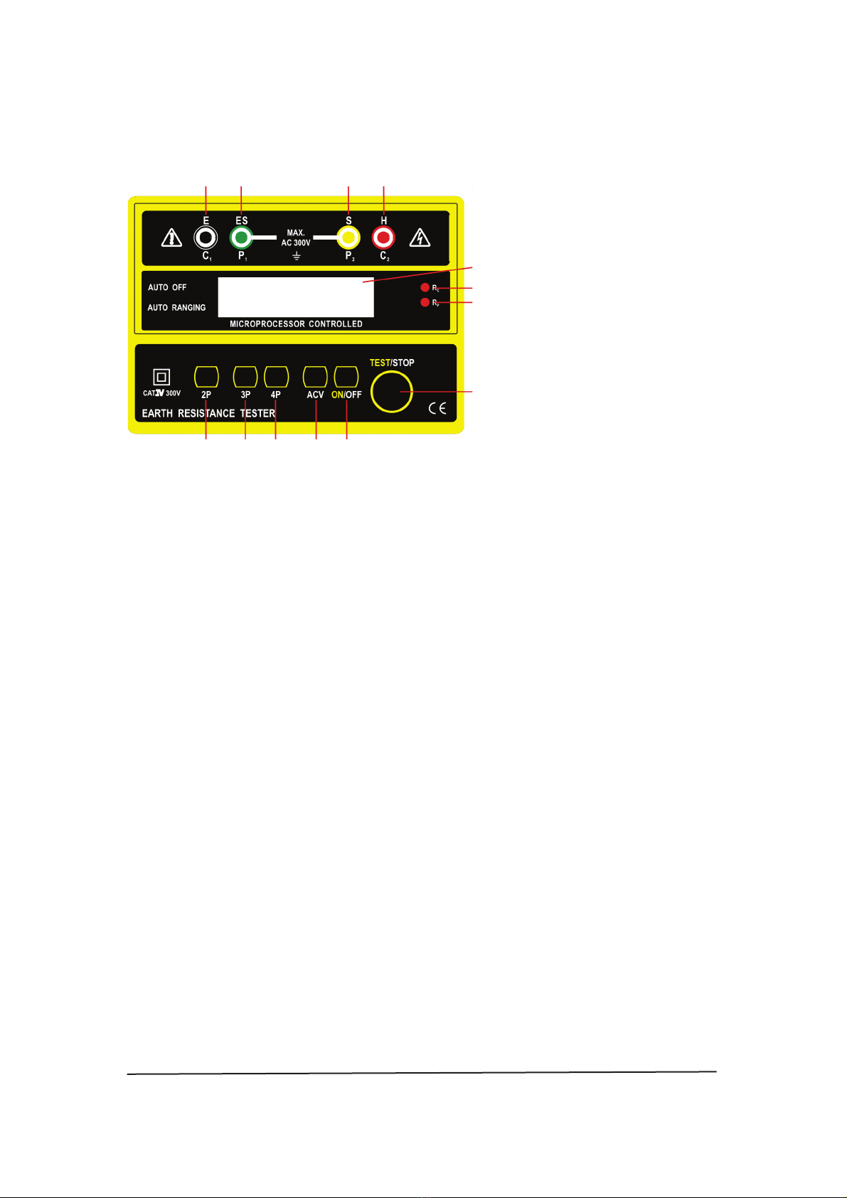
2.- Comprobación de la tensión de tierra
a.- Conexión de las puntas de prueba.
b.- Pulse las teclas “ON/OFF”, “ACV” y “TEST/STOP”, la tensión a tierra se
mostrará en la pantalla. Cuando la tensión a tierra sea superior a 10V, pueden
producirse errores en la medida de la resistencia a tierra. Asegúrese de que el
valor indicado sea inferior siempre a 10V.
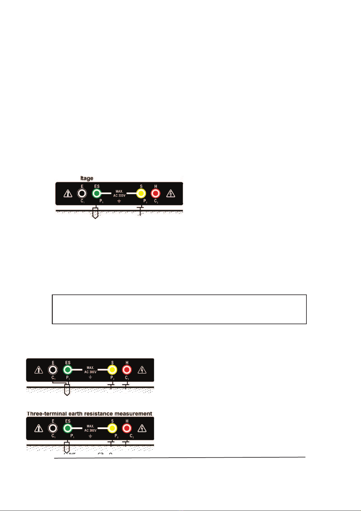
3.- Medida de la resistencia a tierra
Los resultados medidos pueden verse influidos por inducción si las mediciones
se hacen con los cables de las puntas de prueba trenzados o conectados entre
sí. Cuando conecte las puntas de prueba, compruebe que los cables están
separados.
a.- Conexiones de las puntas de prueba

AD Instruments
_____________________________________________________________________
©Copyright Abacanto Digital SA.
Manual de usuario AD4234
9
Medida de la resistencia a tierra –3 terminales
b.- Seleccione del tipo de comprobación: “2P”, “3P” o “4P” y pulse la tecla
correspondiente.
c.- Pulse la tecla “TEST/STOP” para efectuar la medida y obtener la lectura
en la pantalla.
* Cuando realice una medida con 4 cables, si la pantalla muestra “Vp
Error”, cortocircuite C1 (negro) y P1 (verde).
Inserte siempre profundamente las tres picas auxiliares de tierra. La
distancia debe de ser de 5 a 10m entre las picas auxiliares de tierra.
Notas:
Compruebe lo siguiente antes de efectuar una medida:
1.- Si se enciende el LED ‘Rc’ compruebe si las picas auxiliares están conectadas
correctamente.
2.- Indicaciones para ‘Rc’ y ‘Rp’
Rc: Cuando se ilumina el LED ‘Rc’, significa que no hay corriente de salida
en la prueba.
Detenga la medida, y compruebe los puntos relevantes de prueba.
Rp: Cuando se ilumina el LED ‘Rp’, significa que el valor de resistencia ‘R’
mostrado en la pantalla ‘>2KΩ’, esto quiere decir que la resistencia a tierra
es superior a 2KΩ.

AD Instruments
_____________________________________________________________________
©Copyright Abacanto Digital SA.
Manual de usuario AD4234
10
Sustitución del fusible
PRECAUCIÓN
Sólo reemplace el fusible por otro de las mismas especificaciones
1.- Desconecte los cables de las puntas de prueba del equipo.
2.- El fusible se encuentra ubicado en la parte de abajo, en el compartimiento
para las baterías.
3.- Abra la lata de las baterías. A continuación sustituta el fusible viejo por otro
de iguales características.
4.- Ponga de nuevo la tapa y fíjela con su correspondiente tornillo.
Especificaciones de fusible: 0,1A / 250V, 5x20mm

AD Instruments
_____________________________________________________________________
©Copyright Abacanto Digital SA.
Manual de usuario AD4234
11
Mantenimiento
PRECAUCIÓN
No mezcle baterías viejas y nuevas juntas.
Sustitución de las baterías
Cuando aparezca en la pantalla la indicación “Battery Low” sustituya las
baterías siguiendo el procedimiento siguiente:
1.- Desconecte las puntas de prueba del equipo, a continuación quite la tapa
situada en la parte inferior del equipo, y por último quite las baterías viejas.
2.- Ponga 8 x 15,V AA baterías nuevas cuidando de mantener la polaridad
correcta.
3.- Reinstale el compartimiento de baterías y la tapa.
Limpieza y almacenamiento
PRECAUCIÓN
Para evitar descargas eléctricas o dañar el equipo,
nunca deje que entre agua en el interior del equipo.
Limpie periódicamente la carcasa con un paño humedecido con agua jabonosa,
no use nunca abrasivos o disolventes.
AD Instruments
_____________________________________________________________________
©Copyright Abacanto Digital SA.
Manual de usuario AD4234
12
Manual de Usuario ADInstruments
Comprobador de resistencia a tierra de 4 cables
AD4234

AD Instruments
_____________________________________________________________________
©Copyright Abacanto Digital SA.
Manual de usuario AD4234
13
INDEX PAGE
1. INTRODUCTION ………………………………………………………14
2. SAFETY NOTES ………………………………………………………..14
3. FEATURES ……………………………………………………………….15
4. SPECIFICATIONS ………………………………………………………15
5. INSTRUMENT LAYOUT ………………………………………………16
6. MEASURING METHODS ……………………………………………..17
7. FUSES REPLACEMENT ………………………………………………..19
8. MAINTENANCE ……………………………………………………… 20
Due to our policy of constant improvement and development, Abacanto Digital
S.A. reserves the right to change specifications without notice.

AD Instruments
_____________________________________________________________________
©Copyright Abacanto Digital SA.
Manual de usuario AD4234
14
1. INTRODUCTION
This meter has been designed and tested according to
the IEC Publication 348, safety requirements for Electronic
Measuring Apparatus, EN 61010-1, EN 61326-1, EN 61557-1
EN 61557-5 and other safety standards.
2. SAFETY NOTES
• Read the following safety information carefully before attempting to operate
or service the detector.
• Use the meter only as specified in this manual. Otherwise, the protection
provided by the meter may be impaired.
• Rated environmental conditions:
(1) Indoor & outdoor use.
(2) Installation Category 1V 300V.
(3) Pollution Degree 2.
(4) Altitude up to 2000m.
(5) Relative Humidity 80% max.
(6) Ambient temperature 0—40°C.
• Observe the International Electrical Symbols listed below:
Detector is protected throughout by double insulation or reinforced insulation.
Warning Risk of electric shock.
Caution! Refer to this manual before using the detector.
Earth(ground) terminal.
C E Equipment complies with current EU directives.

AD Instruments
_____________________________________________________________________
©Copyright Abacanto Digital SA.
Manual de usuario AD4234
15
Weight
Approx. 1430g(battery
included)
Accessories
Test leads(red-15m,
black
-lOm,
yellow-lOm,
green
-5m)
Auxiliary
earth
spikes
Instruction
manual
Carrying
case
Batteries
Fuse(0.1N250V 5
x 20mm)
3. FEATURES
• Microprocessor controlled with advanced safety features
• LCM display
• Auto-Ranging
• Earth resistance testing at O-2010-20010-200Q/O-2kC
• Earth voltage measuring : O-300Vac
• Automatic C spike check.
• Automatic P spike check.
• 2-wire test
• 3-wire test
• 4-wire test
• Auto power off
• Data hold
• Robust, compact and easy to carry.
•Safety standard: EN 61010-1 CAT IV 300V EN 61326-1
EN 61557-1
4. SPECIFICATION
Measuring Ranges
Earth Resistance
0-20, 0
-200, 0-2000, 0-2k0
Earth Voltage
0-300V AC
Accuracy
Earth Resistance
±2%rdg±3dgt
Earth Voltage
±2%rdg±3dgt
Earth Resistance
Resolution
0-20 : 0.010
0-200 0.10
0-2000: 10
0-2kC2 0.OlkC)
Temperature &
Humidity
Operating :
0C—50°C80%R.H. Storage :
-1o’C—60C80%R.H.
Power Source 1 .5V(AA) x 8
Dimensions 250(L)x 190(W)x 110(D)mm
AD Instruments
_____________________________________________________________________
©Copyright Abacanto Digital SA.
Manual de usuario AD4234
16
5. INSTRUMENT LAYOUT
1 2 3 4
8 9 10 11 12
1.C1
terminal
(Black test lead
connection)
8.2
Wires type
button
2. P1
terminal
(Green test lead
connection)
9. 3 Wires type
button
3. P2
terminal
(Yellow test lead
connection)
10.4 Wires type
button
4. C2
terminal
(Red test lead
connection)
11.ACV
button
5. LCM
display
12. Power
button
6. Rc
LED
13.
TEST/STOP
button
7. Rp
LED
5
6
7
AD Instruments
_____________________________________________________________________
©Copyright Abacanto Digital SA.
Manual de usuario AD4234
17
©C
©C
©C
op
op
op
op
op
op
op
op
op
op
op
op
op
op
op
op
op
op
op
op
op
op
op
op
op
op
op
op
op
op
op
op
op
op
op
op
op
op
op
op
op
op
op
op
op
op
op
op
op
op
op
op
op
op
op
op
op
op
op
op
op
op
op
yr
ig
ht
A
ba
ca
nt
o
Di
gi
ta
l
SA
6.MEASURING METHODS
1. Battery voltage check
a. Before testing, press the “ON/OFF” button, when the “Battery: Low” appears
on the display, replace with new batteries.
b. Prior to measuring, if “Battery: Low” appears on the display, replace with
new batteries.
2. Earth voltage check
a. Test leads connection.
Earth Va measurement
Earth electrode (rod) under test Test spike
b. Press the “ON/OFF” button, “ACV” button and “TEST/STOP” button, earth
voltage will be displayed on the LCM. When the earth voltage is more than 1OV
It may result in errors in earth resistance measurement. Make sure that the
indicated value is less than 1 OV.
3. Earth resistance measurement
The measured results may be influenced by induction if measurements are
made with the Test Leads twisted or connected each other. When connecting
the Probes, they should be separated.
a. Test leads connections.
Four-terminal earth resistance
measurement
Earth
electrode Potential Current
(rod) under
test spike spike
AD Instruments
_____________________________________________________________________
©Copyright Abacanto Digital SA.
Manual de usuario AD4234
18
Earth
electrode
Potential
Current
(rod) under
test
spike
spike
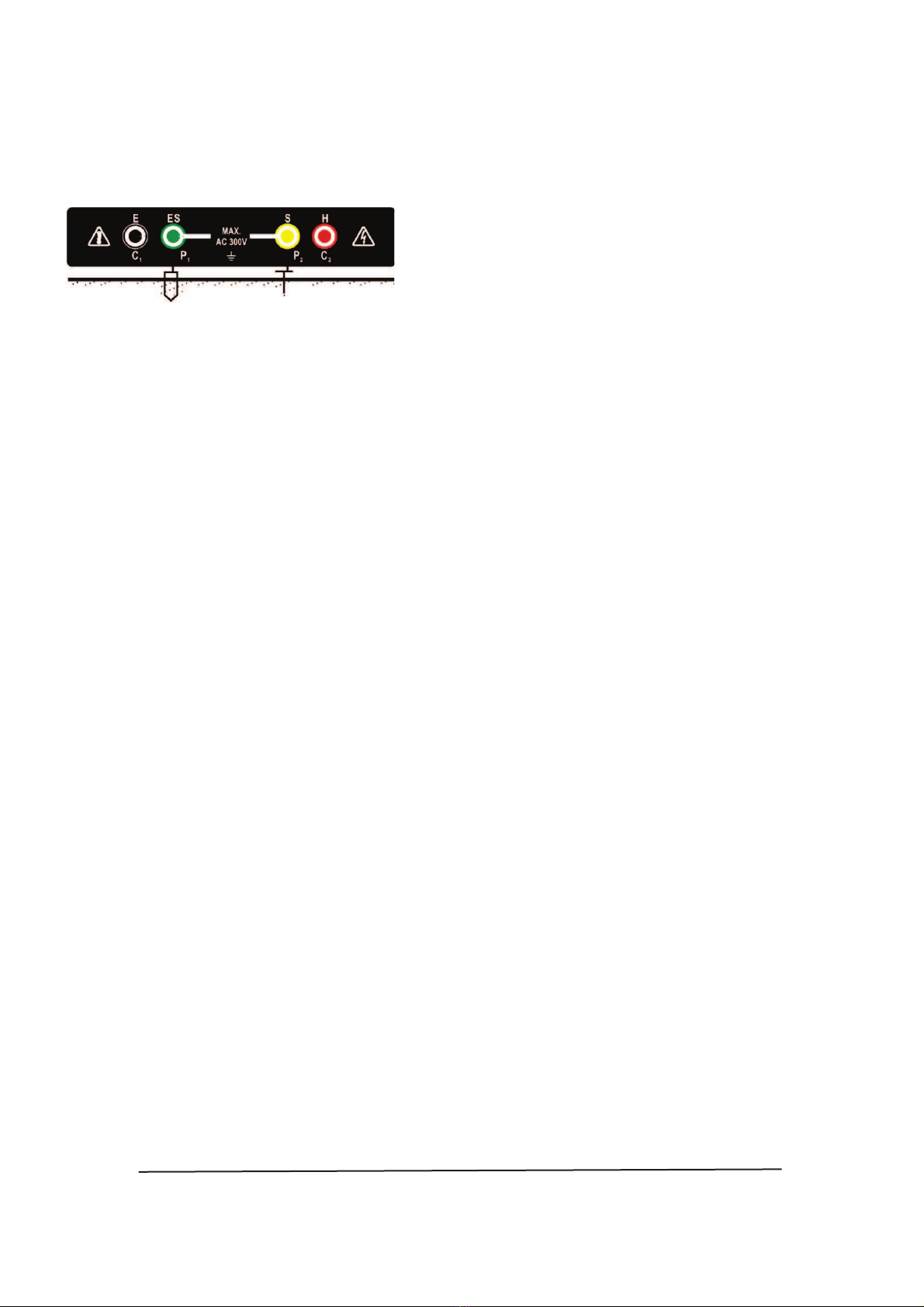
Two-terminal earth resistance measurement
Earth electrode (rod) under
test
Potential spike
b. Select testing type: “2P”, “3P” or “4P” and press button. c. Press
“TEST/STOP” button to test and take a reading.
*When you make the “4P measurement”, LCD shows
“Vp Error”, short circuit Cl (black) and P1 (green).
4Stick the three Auxiliary Earth Spikes into the ground deeply. The distance
must be 5—lOm between theAuxiliary
Earth Spikes.
Notes:
Check the following prior to proceeding with measurement:
1. Checking if Auxiliary Earth Spikes connect correctly when
the ‘Rc’ LED lit.
2. Indication for ‘Rc’ & ‘Rp’
Rc: When the ‘Rc LED lit, this means there is no test current output.
Stop testing and check relevant testing point.
Rp: When the ‘Rp” LED is lit, the ‘R’ value on the LCD
will displayed ‘>2k0’, this means testing Earth
Resistance value is over 2k0.
AD Instruments
_____________________________________________________________________
©Copyright Abacanto Digital SA.
Manual de usuario AD4234
19
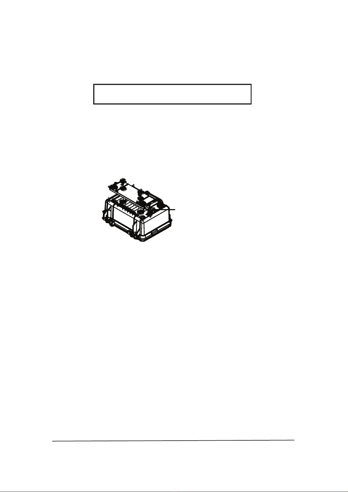
7. FUSE REPLACEMENT
WARNING
Only replace with the same fuse specification
1. Disconnect the test leads from the instrument.
2. The fuse is located under the battery holder.
3. Open the battery cover. Then remove and replace the fusc with the new one.
4. Fix the cover after replacing a fuse and screw up the cover. Fuse Spec.
O.1A1250V, 5 x 20mm
Fuse (O.IA/250V)

AD Instruments
_____________________________________________________________________
©Copyright Abacanto Digital SA.
Manual de usuario AD4234
20
8. MAINTENANCE
WARNING
Do not mix new and old batteries together.
. Battery replacement:
When the “Battery: Low’ appears on the display, replace the batteries as
follows:
1. Disconnect the test leads from the instrument and remove the battery cover
and the batteries.
2. The tester’s battery is situated under the tester.
3. Replace with eight I .5V AA light batteries, taking care tc observe correct
polarity.
4. Reinstall battery holder and the battery cover.
. Cleaning And Storage:
WARNING
To avoid electrical shock or damage to the meter,
do not get water inside the case.
Periodically wipe the case with a damp cloth and detergent: do not use
abrasives or solvents.
Cover
Battery
Table of contents
Languages:


