METREL MI 2014 User manual

Cable Scanner
MI 2014
Instruction Manual
Code No.:20 750 429

2
Distributor:
Manufacturer:
METREL d.d.
Ljubljanska cesta 77
1354 Horjul
Slovenia
web site: http://www.metrel.si
e-mail: metr[email protected]
Mark onyourequipment certifies thatthisequipment meets the requirementsofthe
EU (European Union)concerning safetyand interference causing equipment
regulations
© 2003 METREL
No part ofthis publication maybe reproduced or utilized in anyform or byanymeans
without permission in writing from METREL.

MI 2014 Cable Scanner Table of contents
3
1. Cable Scanner MI 2014.............................................................................................4
Section I General information....................................................................................5
2. Safetyand operational precautions........................................................................5
2.1 Warnings...............................................................................................................5
2.2 Batteryreplacement..............................................................................................5
2.3 Service and recalibration......................................................................................5
2.4 Maintainance and cleaning...................................................................................6
3. Cable scanner description.......................................................................................7
3.1 Front panel............................................................................................................7
3.2 Connector panels................................................................................................10
3.3 Bottom................................................................................................................10
4. Standardremote units description........................................................................11
5. Talk remote unit description..................................................................................11
Section II Specifications...........................................................................................12
6. Standardset............................................................................................................12
7. Optional accessories..............................................................................................12
8 Technical specifications..........................................................................................13
8.1 Fast Test.............................................................................................................13
8.2 Complete Test (with Remote units).....................................................................13
8.3 Length & Reflections...........................................................................................13
8.4 Locators..............................................................................................................14
8.5 Tracer.................................................................................................................14
9. General specifications............................................................................................15
9.1 General Data......................................................................................................15
9.2 Output connector, patch cable wiring: T568B.....................................................15
Section III Cable Scanner operation........................................................................16
10. Fast test.................................................................................................................16
11. Complete test........................................................................................................18
12. Length and reflections..........................................................................................20
12.1 Cable Length Calibrations.................................................................................24
13 Locators – Identification of cables.......................................................................26
14. Tracer– Tracing of cables and wires..................................................................27
15. Talk & Trace function............................................................................................28
15.1 Establishing a voice communication.................................................................28
15.2 Breaking off the connection..............................................................................29
15.3 Locating cables.................................................................................................29
15.4 Talk Remote Unit operation..............................................................................29
16. Cable type..............................................................................................................30
17. Reinitialisation (setting default values / length unit )........................................31
MI 2014 Cable Scanner Cable Scanner MI 2014
4
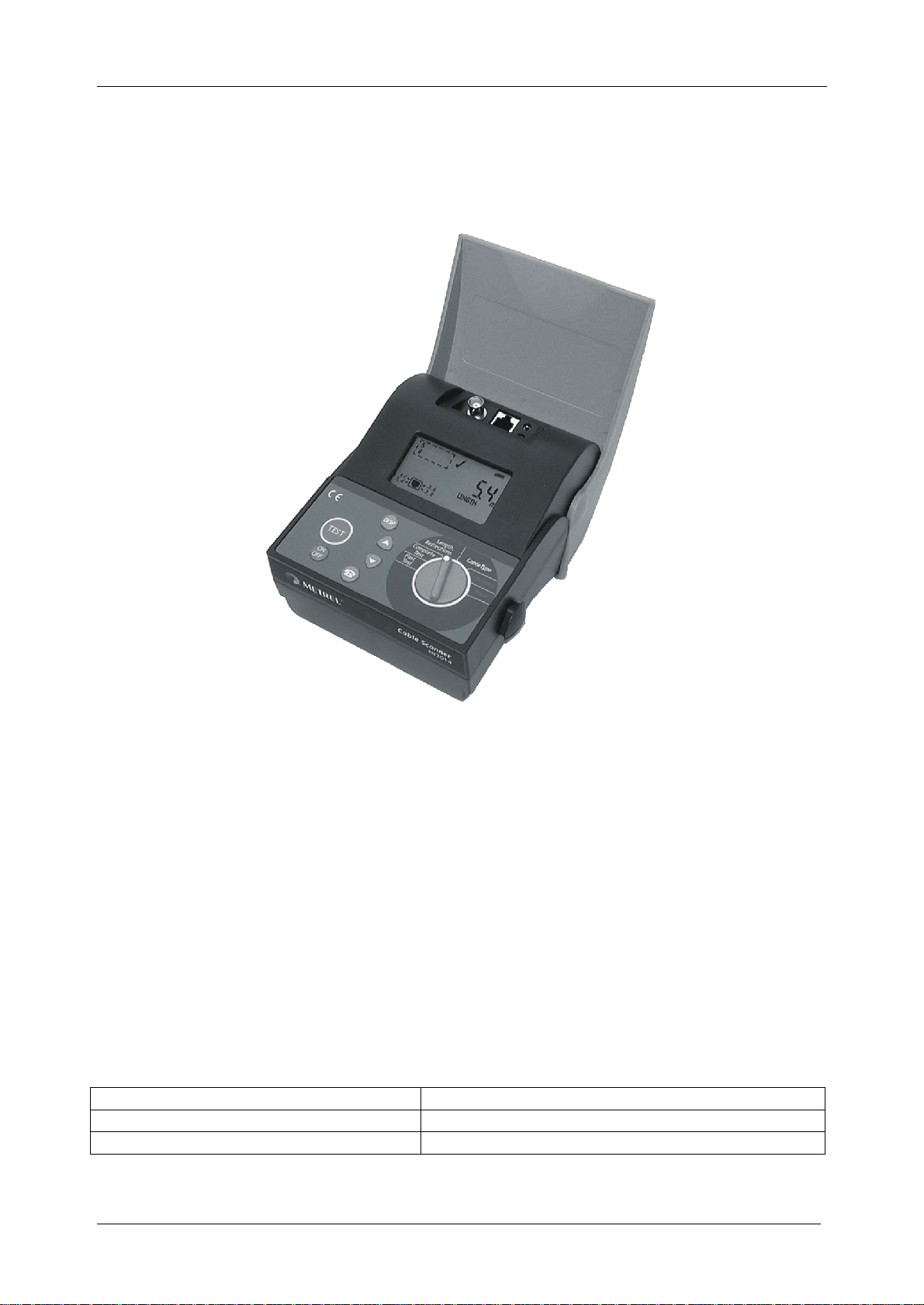
1. Cable Scanner MI 2014
The Cable Scanner Tester is a portable handheld batterypowered instrument intended
for testing LAN installations and cables.
Main features
• Fast Cable Test : most ofconnectivitytests can be performed byone operater
• Complete Cable Test (with Remote Unit): performs complete cable
connectivity test
• Cable identification (with Remote Unit or Locators)
• Cable length up to 300m, calibration facilities for accurate length measuring
• Amplitude and location of reflections are provided byan in built Time Domain
Reflectometer.
• Tone generator for tracing hidden cable paths and wire determination
• Talk function for communication over the cable link (with optional Talk Remote
unit)
• Supports coaxand twisted pairs cables
The instrument is supplied with all accessories necessaryfor carrying out the tests.
The manual is divided into three sections, each covering a particular aspect ofthe
operation.
Section I General information
Section II Specifications
Section III Cable Scanner operation

MI 2014 Cable Scanner Section I General information
5
Section I General information
2. Safetyand operational precautions
2.1 Warnings
Ø Never connect the test equipment to an active network.
Ø Service is allowedto be carried out onlybyan authorised person!
Ø Use onlystandard or optional test accessories supplied byMetrel!
Ø Use onlyconnector types equivalent to those built in to avoid damage to the
instrument components.
Ø If the test equipment is used in amanner not specified in thisUsers Manual,
the protection provided bythe equipment maybe impaired!
2.2 Batteryreplacement
Note
• Insert cells correctly, otherwise the instrument will not operate and the batteries
could be discharged.
• If the instrument is not to be used for a long period of time, remove all batteries from
the batterycompartment.
• Batterycompartment is protected with a fuse to prevent abnormal use ofbattery.
• External charger is not intended for supplying the instrument without batteries.
Warnings
Ø Do not charge alkaline batteries.
Ø Use onlychargers delivered from Metrel or distributor of the test equipment to
avoid possible fire orelectric shock.
Ø In case of blown fuse consult your distributor.
2.3 Service and recalibration
It is essential that test instrument is regularlycalibrated in order technical specification
listed in this Instruction Manual to be guaranted. We recommend the calibration to be
carried out once per 2 years.
Metrel encloses to everynewinstrument an original calibration certificate.
For recalibration and repairs under or out of warrantytime please contact your
distributor for further information.
Name and address ofmanufacturer:
METREL d.d.
Ljubljanska 77
SI-1354 Horjul
Tel.: +386 1 755 82 00
Fax.: +386 1 754 92 26
http://www.metrel.si;
E-mail:metrel@metrel.si

MI 2014 Cable Scanner Section I General information
6
2.4 Maintainance and cleaning
Use a soft cloth, slightlymoistened with soapywater, or cleaning alcohol, to clean the
surface ofthe instrument. Leave the instrument to drycompletelybefore using it.

MI 2014 Cable Scanner Section I General information
7
3. Cable scanner description
3.1 Front panel
FUNCTIONSWITCH
KEYPAD
LCD

MI 2014 Cable Scanner Section I General information
8
Front panel layout
Function switch selects one ofsixfuctional/operating menus:
Functional Menu Description
FAST TEST
Fast connectivityandTDR test (no Remote unit needed):
- determines cable length or termination
- finds cause and location of most frequently cable and
connectivity faults
COMPLETE TEST
Complete connectivityand TDR test (with Remote unit):
- determines cable length
- finds cause and location of all possible cable and connectivity
faults
- cable identification
LENGTH&
REFLECTIONS Complete TDR cable check, calibration facilities
- finds cable length and termination
- location and amplitude of cable reflections.
- calibration facilities (on base of known NVP or cable length)
for accurate length measurements
CABLE TYPE Selectable 7 different cable types and wiring standards
LOCATORS Identification ofup to 26 cables
TRACER Tracing of cables and wires (with optional Tracer)
Keypad
, ………… Selecting cable type, viewing subresults, calibration parameters
………………Selecting calibration type, viewing subresults
……………….To turn on or offthe instrument (Auto off after 10 minutes)
……………….Talk&Trace interface for talking over cable/ locating the Talk Remote
Unit
……… ……Startstest procedures, confirmation of selected items
Display
MI 2014 Cable Scanner Section I General information
9
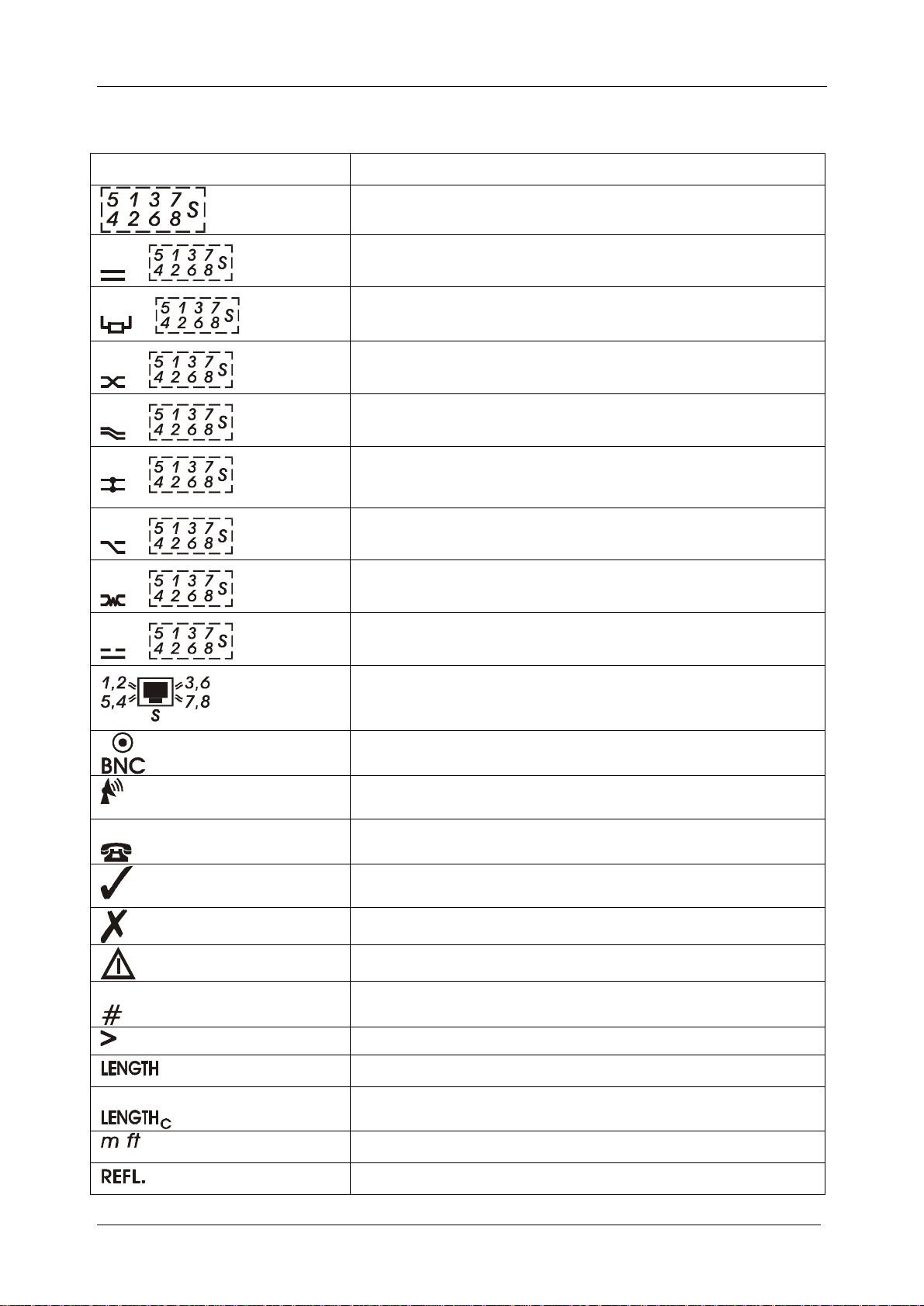
Description of displayed symbols
SYMBOL NAME
Wires/ Pairs result field
+
Unselected wires / pairs connected
+
Pair terminated
+
Wiresreversed
+
Pair crossed
+
Wires/ pairs shorted, short to shield
+
Unknown connectivityfault
+
Splited pair
+
Broken / open wire, shield
Selected twisted pair cable standard / type
Coaxcable selected
Tone Generator active
Talk & Trace function active
Test passed
Test failed
Warning (redundant pairs / reflectionsdetected)
Cable Identification Number is displayed
Result out of limit
Distance / Amplitude oflength is displayed
NVP calibrated on known cable length (for precize
length mesurements)
, Meters, feets
Distance / Amplitude ofreflection is displayed
MI 2014 Cable Scanner Section I General information
10
Nominal velocityofpulse is displayed
Faults / Reflections / Redundant connectionsare
displayed
Disconnect the Remote unit (Fast Test) / No Remote
detected (Complete Test)
Batteryindication (change batteryifno segment is
displayed)
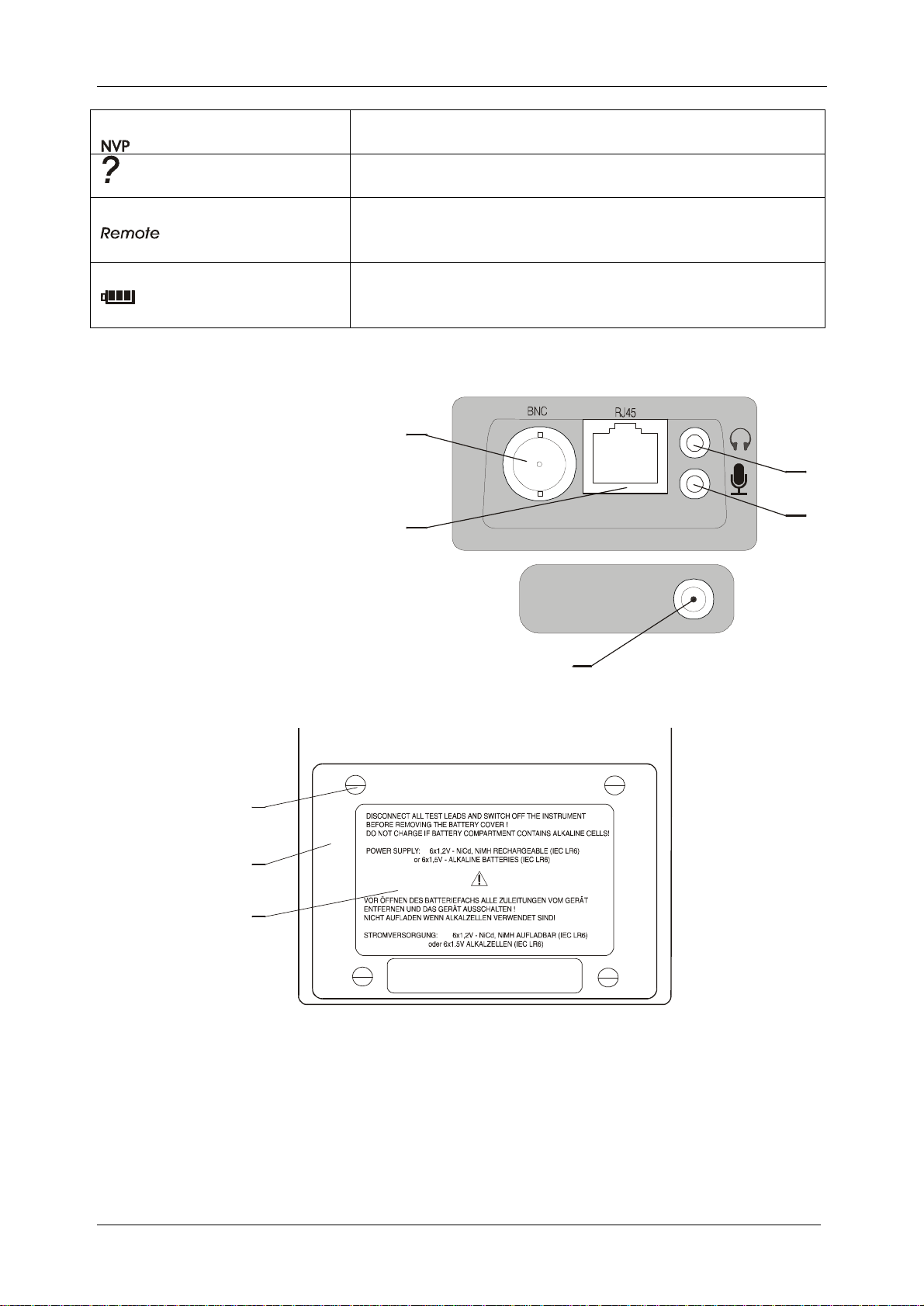
3.2 Connector panels
1. RJ 45 connector
2. BNC connector
3. Audio jack: Microphone input
4. Audio jack: Phone output
5. External charger input
2
4
3
1
5
3.3 Bottom
20224411
3
2
1
Bottom ViewLayout
1. Information label
2. Batterycompartment cover
3. Retaining screws (unsrewto replace batteries)

MI 2014 Cable Scanner Section I General information
11
4. Standard remote units description
1. Male RJ 45 plug
2. Female RJ 45 connector
3. Identification number
5. Talk remote unit description
1. Female RJ 45 connector
2.Audio jack: Microphone input
3.Audio jack: Phone output
4. Batterycompartement
5. On/Offswitch
5
2
¸3
4
1

MI 2014 Cable Scanner SectionII Specifications
12
Section II Specifications
6. Standard set Ordering number
MI2014
Cable Scanner
Cat 5 Patch Cable Metrel PC-2, 1pc
Standard Remote #1
Locators #1 - #4
Cable Scanner User Manual
Calibration Certificate
List ofwarranty
Declaration ofconformity
7. Optional accessories
Talk Remote Unit set
Headphones set
S 2004
Standard remote set #2-#6
Standard remote set #7-#15
Batterycharger with NiCd batterypack
S 2005
S 2006
Locator set II (#5..#16) A1044
Locator set III (#17..#28) A1045
Tracer
A1082

MI 2014 Cable Scanner SectionII Specifications
13
8 Technical specifications
8.1 Fast Test
RJ45 output only
Length (highest distance ofall pairs is shown, refer to 3.3 for accuracy)
Detection of:
- broken wire on connector or cable + distance to fault
- short between wires + distance to fault
- short to shield
- split pairs
- cable termination
8.2 Complete Test (with Remoteunits)
RJ45 output only
Length (highest distance ofall pairs is shown, refer to 3.3 for accuracy)
Detection of:
- broken wire on connector or cable + distance to fault
- short between wires + distance to fault
- short to shield
- splited, crossed, reversed, transposed pairs
Cable identification #1 - #15
8.3 Length & Reflections
Measuring principle:Time Domain Reflectometer
Output impedance: 100 RJ45 output, 50 BNC output
Twisted Pair cable
Distance Resolution Accuracy
0.0 – 99.9m
100 – 300m 0.1m
±(3%+5dig) of reading
±(5%+1dig) of reading
Amplitude Range
-99% - 100% 1% ±(5%+5dig) of reading
Coaxcable
Distance Resolution Accuracy
0.0 – 99.9m
100 – 300m 0.1m
±(3%+5dig) of reading
±(5%) ofreading
Amplitude Range
-99% - 100% 1% ±(5%+5dig) of reading
Calibration (see page 20)
Calibration cable length adjustable 2m – 200m
Propagation velocityrate (NVP) adjustable 0.50-0.99

MI 2014 Cable Scanner SectionII Specifications
14
Up to three highest reflections (faults) are reported.
Additional error sources that must be considered when measuring length:
UncertainityofNVP (nominal propagation speed)
Pulse attenuation at high frequencies effects the accuracyat long distances(over
100m).
Accuracyoflength is defined on opened, shorted and with remote unit terminated
cables only.
8.4 Locators
Locators #1 - #28
8.5 Tracer
Tone generator frequency0.80kHz..1.20kHz
Tone generator amplitude RJ45 output: 7V
BNC: 5V

MI 2014 Cable Scanner SectionII Specifications
15
9. General specifications
9.1 General Data
Display: custom, 85 segments
Operating temperature range: 5°C÷40°C
Storage temperature range: 0°C÷70°C
Relative humidity: 90% up to 40°C declining to 70% up at 45°C
Pollution degree: 2
Protection degree: IP44
Power supplymain unit:
6x1.5V AA alkaline batteries or
6x1.5 NiCd or NiMH AA rechargeable batteries
Charger input (nominalcharge voltage): 9V=
Typical batterylife (alkaline batteries): 10 hours
Talk remote unit supply:
9V alkaline battery
Typical batterylife (alkaline battery): 25 hours
Auto Offtime: 10 min
Standards applied: EMC: EN50081-1,EN50882-1
Safety: EN61010-1
9.2 Output connector, patch cable wiring: T568B
Pair 1: wire 5, blue-white
wire 4, blue
Pair 2: wire 1,orange-white
wire 2, orange
Pair 3: wire 3, green-white
wire 6, green
Pair 4: wire 7,brown-white
wire 8, brown

MI 2014 Cable Scanner Section III Cable Scanneroperation
16
Section III Cable Scanner operation
10. Fast test
The Fast Test function enables fast and convenient checking ofthe installation. Its main
advantage is that the test can be performed byone person, without using the Remotes.
Most likelyconnectivity faults like bad contacted connector and shorts between wires
can be found with Fast Test. The cable length is also reported, together with the
distance to eventual problems.
We recommend to use this test for fast connectivitychecks during bulding ofthe
installation.
For thorough cable connectivitytests the Complete Test should be used.
For thorough cable qualitytests the Length&Reflections function should be used.
Typical Cable Scannerconnectionsin Fast Test
Test procedure
1. Select Fast Test with rotaryswitch.
2. Checkthe selected cable type and pin configuration (refer to chapter 8 for more
information), Connect the cable under test to the instrument and press .
If the test passed succesfullyfollowing items
are displayed:
- the sign
- the cable length
- correctlyconnected wires
test successfullypassed

MI 2014 Cable Scanner Section III Cable Scanneroperation
17
If one or more faults are detected following
items are displayed:
- the and signs
- correctlyconnected pairs
- length ifavailable (depends on the kind of
the fault)
test failed, wires 5,1,2,3,6,7 correctlyconnected
The related wires, type and distance to fault
(ifavailable) can be viewed byusing and
keys. During displaying faults the sign
is displayed.
test failed, shorted wires 4 and 8 at 2.2m
If the test passed succesfullyon the cable
pairs defined in selected Cable Type but
other connections were found that are not in
accordance with the defined cable type
following items are displayed:
- the and signs
- the cable length
- correctlyconnected pairs
test conditionallypassed, unselected connected
wires detected
The redundant wire and pairs connections
can be viewed byusing and keys.
During displaying them the sign is
displayed.
test conditionallypassed(shorted wires 4and 8 at
2.2m.The wires arenotdetermined in the selected
cable type)
test conditionallypassed (Pair 4 is connected. The
pair is not determined inthe selected cable type)
Note:
The Fast Test is considered to be performed on cables opened at the far end. Ifthe
cable is terminated bya hub the termination is detected and displayed asa fault.
If a Remote is connected at the far cable end Remote is displayed and the test is not
performed.
Fast Test is not applicable when BNC output is selected.
Broken wires (inside the length tolerances) close to the the far end can't be detected
with this test.
Length can't be measured on terminated cables.

MI 2014 Cable Scanner Section III Cable Scanneroperation
18
11. Complete test
Complete test checks the installation against all possible connectivityfaults. Beside the
complete connectivitytest the cable identification and cable lenght are performed.
Remote units must be connected to the far cable end while performing Complete Tests.
We recommend to use this test after the installation is built and before certifying it.
For thorough cable qualitytests the Length & Reflections function should be used.
Typical Cable Scanner connections in Complete Test
Test procedure
1. Select Complete Test with rotaryswitch.
2. Checkthe selected cable type and pin configuration (refer to chapter 8 for more
information). One ofthe Remote Units must be connected at the far cable end.
Connect the cable under test to the instrument and press .
If the test passed succesfullyfollowing items
are displayed:
- the sign
- the identification number
- correctlyconnected wires
test successfullypassed
With the keyit can be switched between length and identification number (if
available).
If one or more faults are detected following
items are displayed:
- the and signs
- correctlyconnected pairs
- the identification number ifavailable
(dependson the kind ofthe fault)
test failed, wires 1 to 8 correctlyconnected

MI 2014 Cable Scanner Section III Cable Scanneroperation
19
The related wires, type and distance to fault
(ifavailable) can be viewed byusing and
keys. During displaying faults the sign
is displayed.
test failed, shield is broken or not connected
If the test passed succesfullybut additional
connections were detected that are not
defined in the set Cable Type following
items are displayed:
- the and signs
- the identification number ifavailable
- pairs connected according to the set type
test conditionallypassed, unselected connected
wires 1,2,3,6detected
Byusing keyit can be switched between length and identification number (if
available).
The redundant wire and pairs connections
can be viewed byusing and keys.
During displaying them the sign is
displayed.
test conditionallypassed (pair 2 is connected. The
pair is not determined inthe selected cable type)
Note:
If no Remote Unit is connected at the far cable end ?Remote is displayed.
Remotes #1 - #5 are applicable on all cable types.
Remotes #6 - #15 are applicable onlyon cables where all 4 pairs are used.
Complete Test is not applicable when BNC output is selected.

MI 2014 Cable Scanner Section III Cable Scanneroperation
20
12. Length and reflections
This function enables accurate cable length and qualitymeasurements. Up to 3 largest
reflections caused bycable damages, impedance mismatchesor other reasons are also
detected.
There are manyapplications where the Length & Reflection test can be used
- checking newcables against possible damages
- checking cable lengths
- determining location ofcable problems (broken, shorted, damaged cable)
- checking connection and junction points quality
The in built Time Domain Reflektometer provides the distance and amplitude
information of
reflected pulses. That helps to determine the reason ofcable problem.
Typical Cable Scannerconnectionsin Length & Reflections Test
Amplitude information
The amplitude ofthe reflected pulses is available as a subresult providing important
information about the cause ofproblem (exessive attenuation, shorted or open end,
improper termination, unproper connector assembling etc) – see pictures below.
100% equals the amplitude ofthe pulse at the output connector into a 100ΩUTP Cat 5
cable.
Pulse length, reflections
Due to cable attenuation along the cable the reflected pulse weakens when the distance
increases.
Three pulse lenghts are used to compensate for the cable attenuation.
Special algorithms are used to evaluate the 3 largest reflections regardless ofthe pulse
energyand to differ between length and reflections.
Table of contents
Other METREL Cable Tester manuals


