Adjust-a-Sink E140 Series User manual
Adjust-A-Sink® System by Accessible Systems Inc. | Minneapolis, MN | 612-238-4600 | www.adjustasink.com
1 of 25
3/2023
There are three keys to a successful installation:
1. Locate the drain rough-in along the centerline of the installed sink system. Hair interceptors
need to be aligned straight back to not interfere with the moving shroud when fully assembled.
If the rough-in is not on center and you are installing on a cabinet – correct the offset within the
cabinet bulkhead space.
2. This unit requires both supply lines installed on the left of the drain connection.
3. Secure the telescoping drain and verify the full range of vertical motion of the sink FIRST,
then connect the trap between the drain and rough-in. You may need to construct a trap from
components to get the elevations to align.
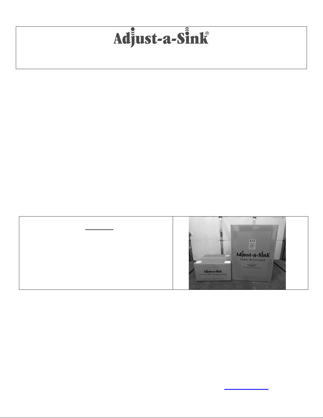
Your system comes in two boxes, what is
included:
Shampoo Bowl box (left in photo):24”x26”x15”, 36
lbs. Contains the 3050 bowl, bowl, fixtures, spray hose,
and vacuum breaker or backflow preventer.
E140 box: 14” x 28” x 39”, 95 lbs. Contains the main
unit lift system, panels and shrouds.
Required Hardware/Supplies Not Included: 1 ½” UPC Listed P-Trap, 90 Degree Supply line shut-off valves,
Lag Bolts and/or 5/16” Bolts-Washers-Nuts (if mounting to cabinet), Plumbing Supplies such as Plumbers Putty,
Sealant, Silicone Caulk, etc.
For replacement part orders or further information please contact Customer Service at: (612) 238-4600
Local Building Codes May Apply. Adjust-a-Sink® is a registered trademark of Accessible Systems, Inc.
E140 SERIES
**INSTALLATION INSTRUCTIONS**
Adjust-A-Sink® E140 System by Accessible Systems Inc. | Minneapolis, MN | 612-238-4600 | www.adjustasink.com
2 of 25
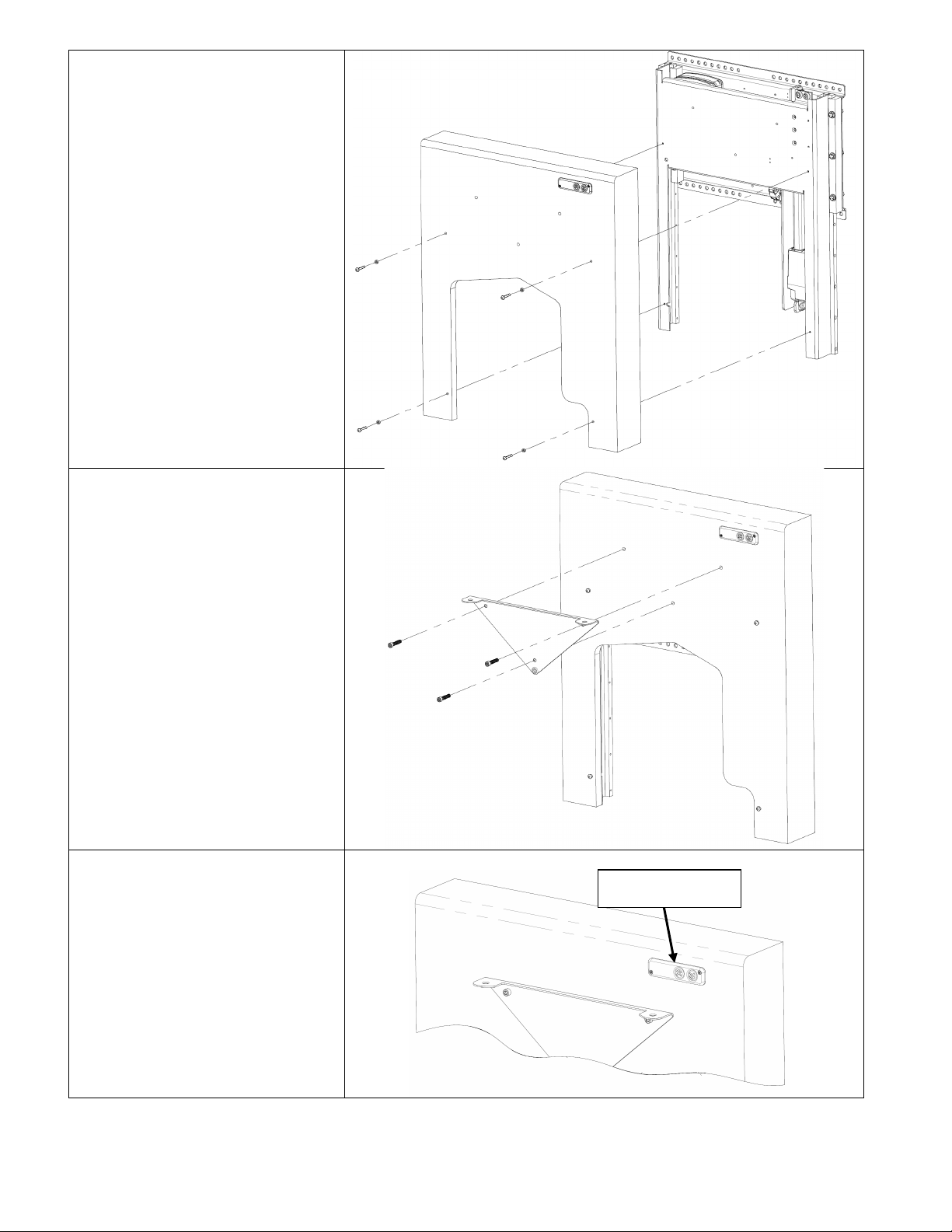
STEP 1: SITE EVALUATION, PLUMBING ROUGH IN, & MOUNTING PANEL PREPARATION
The Adjust-a-Sink® System is designed to be mounted directly to the face of a finished interior
wall, with the proper rough-in plumbing already installed. The System can also be cabinet or
station mounted by a qualified installer.
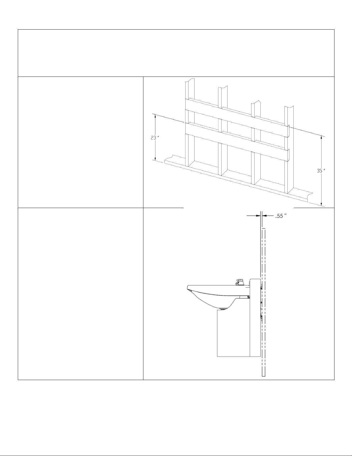
For installation directly on a wall, place
blocking behind finished wall as shown
here:
If mounting to a cabinet, have the
bulkhead section constructed of ¾”
plywood and mounted securely to framing
members.
The adjustable backsplash requires
adequate clearance to lift. The
clearance to the back wall surface is ½
inch. Add spacer blocks or panels
behind the unit if trim work or counter
tops will interfere.
Adjust-A-Sink® E140 System by Accessible Systems Inc. | Minneapolis, MN | 612-238-4600 | www.adjustasink.com
3 of 25
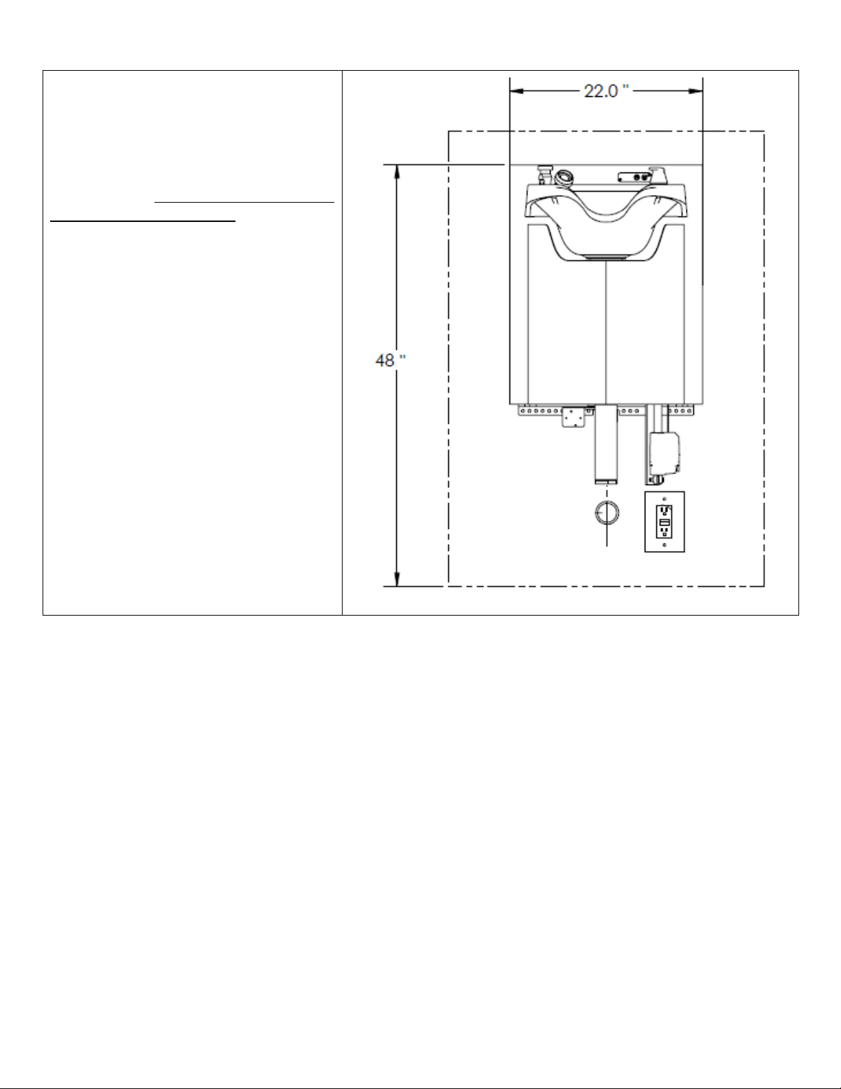
1A. The Adjust-a-Sink is 22” wide and
34” high, the sink and backsplash will
elevate to 48”.
The drain waste rough in should be
centered beneath the sink, the center
of the drain is 10” from the left edge of
the metal mounting panel. Keeping
this in mind will simplify the process.
The supplies should both be located
on the left side of the drain.
A GFCI receptacle should be installed
to the right of the drain. Alternately,
salon workstations typically have
receptacles in a cabinet on the right
side of the sinks, holes can be drilled
and the power cord can be passed
through to these connections. The
E140 comes with a 10’ 3-prong power
cord.
Installed Unit – in UP Position
Please see page 19 of these instructions for the E140 Plumbing Rough-In Drawing
The following Step-by-Step Instructions reference the following Accessible Systems drawings:
E140 Overall Assembly, Sheets 1 through 3
E140 Plumbing Rough-in Drawing (sheet 4)

Adjust-A-Sink® E140 System by Accessible Systems Inc. | Minneapolis, MN | 612-238-4600 | www.adjustasink.com
4 of 25
STEP 2: MOUNTING THE LIFT UNIT
2A. Carefully unpack the balance
of the Adjust-a-Sink® System and
verify all components are included
and undamaged. The Adjust-a-
Sink® System comes with most of
its components already assembled.
For installation on a wall, place
blocking behind finished wall as
shown here. If mounting to a
cabinet, have the bulkhead section
constructed of ¾” plywood and
mounted securely to framing
members.
2B. Install the Lift Unit to the
cabinet or wall using a minimum of
four 5/16” fasteners of appropriate
type and length. Mount the top edge
of the lift unit 32.5” above the floor
for the recommended final bowl
height adjustment range.
Start by securing the unit with a
minimum of two fasteners through
the top row of mounting holes.
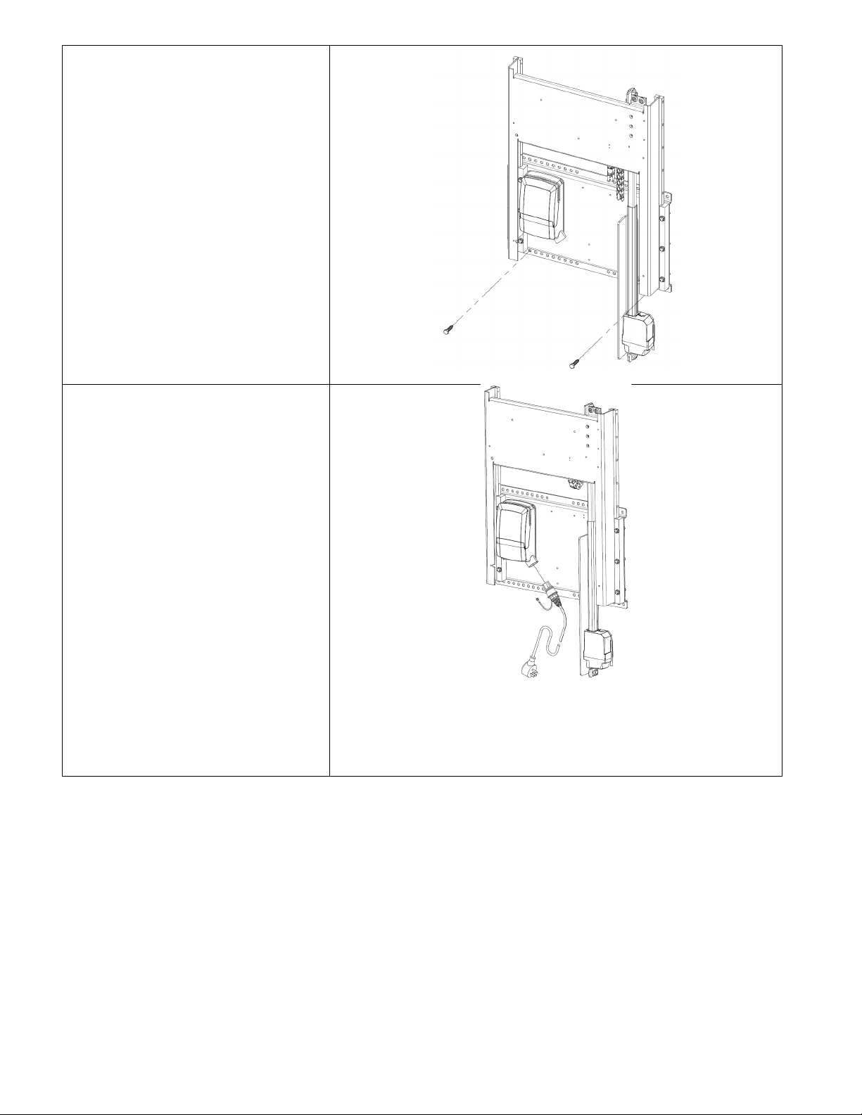
2C. Remove the cable tie which
secures the slide section to the wall
mounting panel section.
Temporarily plug in the unit in and
use the buttons to raise the front
panel to its maximum height, an
extension cord may be needed.
Cable Tie
Adjust-A-Sink® E140 System by Accessible Systems Inc. | Minneapolis, MN | 612-238-4600 | www.adjustasink.com
5 of 25
2D. Install two 5/16” fasteners of
appropriate type and length through
the bottom row of mounting holes.
2E. Unwrap the AC power cord as
needed and plug in to the intended
receptacle.
Press the switches on the upper
right of the lift unit and verify the
vertical travel and movement of the
slide section before continuing with
the installation.
Secure any excess supply cord so it
will not interfere with the slide
sections when in use.
TROUBLESHOOTING:
1. The linear actuator has built-it limit switches, so if it is at the end of travel, it will not move or make
any noise, try the reverse direction switch.
2. The linear actuator has a safety mechanism, so it only pushes the lift up, gravity pulls the lift down.
The slides on a new lift may be tight until break in, and the lift may not drop at this step of the
installation. The unit will drop with the full weight of the assembly and sink installed. You can
push down on the lift to get it back to the bottom position.
Adjust-A-Sink® E140 System by Accessible Systems Inc. | Minneapolis, MN | 612-238-4600 | www.adjustasink.com
6 of 25
2F. Mount the laminated or solid
surface front panel to the slide
section using four #10-32
screws with plastic spacers.
2G. IF your shampoo bowl uses
a bracket, attach it now to the
front panel using ¼-20 x 1-1/4”
bolts.
NOTE: Comfort Fit bowls have
the mounting bracket molded
into the bowl itself, if this is the
bowl you have, skip this step,
there is not separate bracket to
mount.
2H. Test the operation of the
height adjustment buttons on the
front panel. The buttons are
pre-adjusted at the factory to
properly engage the switches on
the lift unit, but can be field
adjusted if needed.
Height buttons
Adjust-A-Sink® E140 System by Accessible Systems Inc. | Minneapolis, MN | 612-238-4600 | www.adjustasink.com
7 of 25
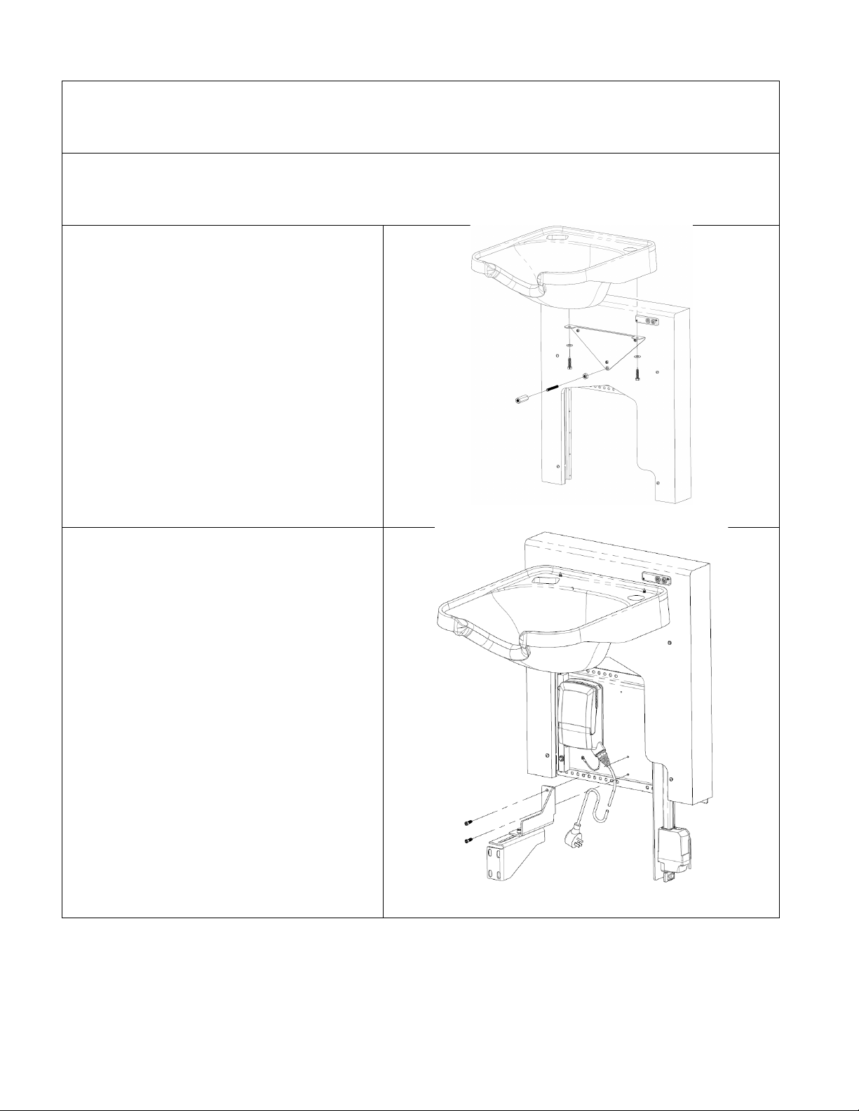
STEP 3: FINISH PLUMBING
3A.Finish the supply water line installation. For both the Hot and Cold, use 1/2” x 3/8” (copper tube
OD x ID) 90-degree Angle Compression Water Supply Shutoffs and Trim Bezels. (Not Supplied)
3B. Shampoo Bowl: Install the faucet, hose and all related pieces to the shampoo bowl per the
instructions provided from the manufacturer.
3C. If you have a Comfort Fit bowl with an
integral molded bracket, mount it directly to
the Front Panel with three ¼-20 x 2” bolts
provided.
If you have a bowl with a separate bracket,
Install the sink leveling bolt onto the sink
mounting bracket, then mount the shampoo
bowl on the Sink Mounting Bracket. Be
sure to level the sink to the Front Panel,
secure its position using the leveling bolt
under the sink and properly secure it by
tightening the nut under each side of the
bowl.
3D. elevate the shampoo bowl to its
highest position. Mount the Drain Support
Bracket assembly onto the mounting panel
using the two ¼-20” x ¾” bolts provided.
Make sure the two 5/16” bolts holding the
Drain Clamp Bracket to the Drain
Support Bracket & the hose clamps are
loose enough to make adjustments.

Adjust-A-Sink® E140 System by Accessible Systems Inc. | Minneapolis, MN | 612-238-4600 | www.adjustasink.com
8 of 25
3E. Install the T1514 telescoping drain to
the end of the drain pipe support bracket
with two hose clamps provided.
With the shampoo bowl still at its
highest position extend the Telescoping
drain to the basket strainer. Connect the
slip joint nut to the basket strainer; make
sure to use the vinyl or rubber slip
joint gasket at the joint. Adjust the Drain
Clamp Bracket so that the Telescoping
Drain unit is plumb to the floor and hand
tighten the two 5/16” bolts holding the
bracket together.
NOTE: It is critical to the
proper operation of the
telescopic drain that the bowl
strainer basket is level, front to
back and side to side, and the
telescopic drain is installed
perpendicular to the floor – any
deviation to this will cause
premature wear and possible
failure of the drain system.
3 F . With the sink in its highest position,
pull down on the base of the telescoping
drain so it is fully extended. Using tape, a
marker or other means, mark along the
top of the hose clamp. Tighten one hose
clamp enough so the drain will not slide
for the next step.
Pull down -
Mark above
hose clamps
Adjust-A-Sink® E140 System by Accessible Systems Inc. | Minneapolis, MN | 612-238-4600 | www.adjustasink.com
9 of 25
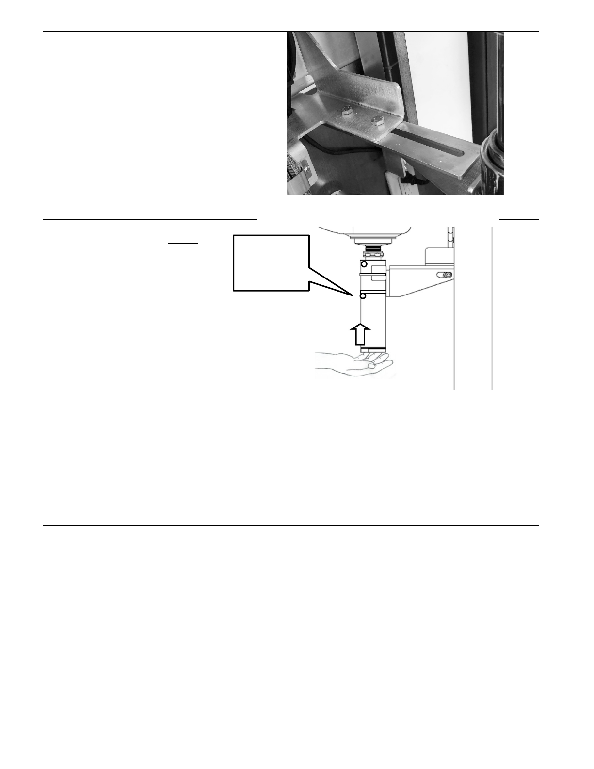
3G. Now move the unit to the lowest
position and fully tighten the two 5/16”
bolts holding the pipe clamp to the drain
support bracket making sure the drain is
still plumb and parallel. Also make
sure the bracket is aligned with the
bottom section of drain before tightening.
3 H . With the sink in its lowest
position, loosen the hose clamps
enough to slide the base of the
telescoping drain up so it is fully
contracted. Using tape, a marker
or other means, scribe a line on
the drain unit along the bottom of
the hose clamp.
Push up -
Mark below
hose clamps

Adjust-A-Sink® E140 System by Accessible Systems Inc. | Minneapolis, MN | 612-238-4600 | www.adjustasink.com
10 of 25
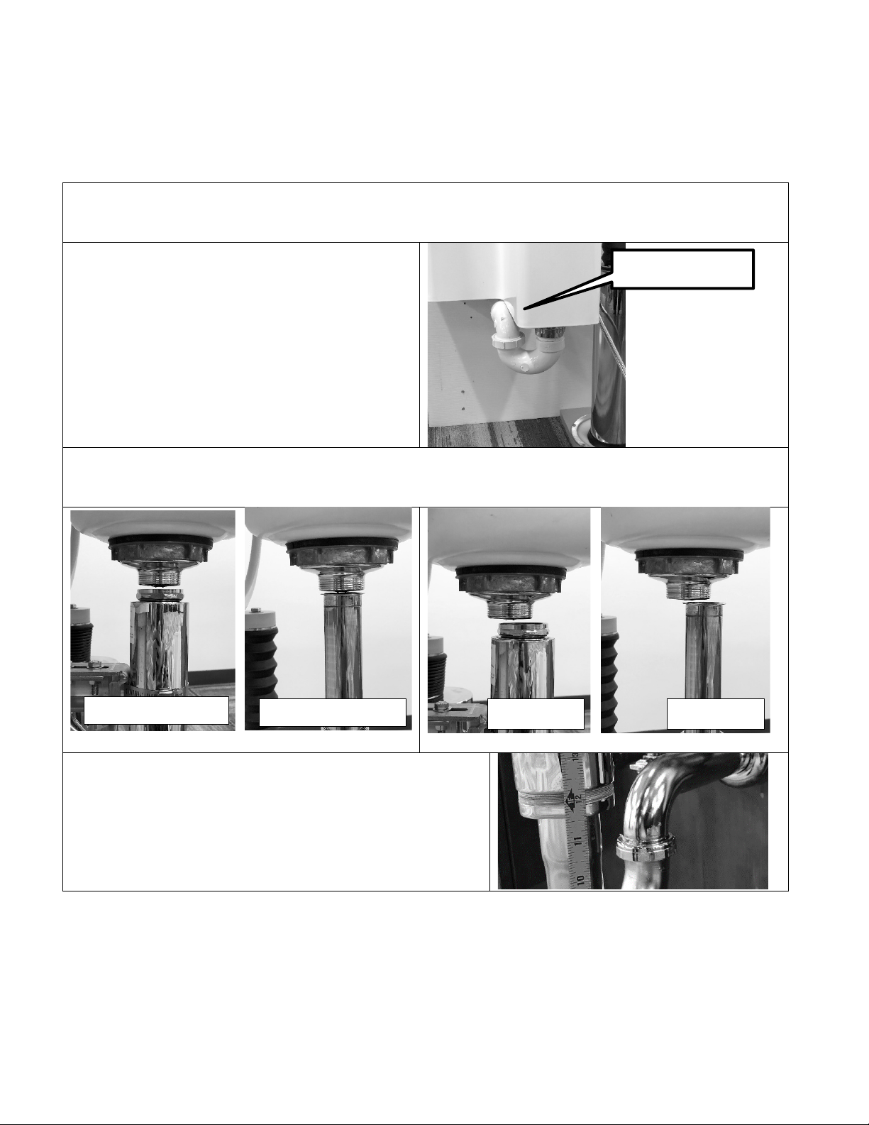
3 i . Adjust the base section of
the drain unit up about ¼” from
full extension, centering the hose
clamp between the marks made,
and tighten the hose clamps.
Move the sink to both up & down
extremes to check for binding.
Make any minor adjustments to
eliminate any binding before
proceeding.
NOTE: When the unit is installed
at the recommended height, the
bottom of the drain should be
between 11” and 12” from the floor
when correctly positioned.
3J. Dry fit the bottom of the
Telescoping Drain to the
wastewater drain pipe using a
UPC approved P-Trap or a hair
trap (not supplied). The outlet
is 1-1/2” FPT. Use appropriate
plumbing methods to seal and
secure the P-trap to the drain
and the roughed in waste outlet.
Do not glue the P-Trap until
you conduct the Initial Testing
Procedure on the following
page.
CAUTION: Consider proper alignment when performing the final connection of the P-Trap to the
Telescoping Drain and wastewater drain pipe. The Telescoping Drain cannot be allowed to bind; the
motion should be smooth and continuous. After P-Trap installation and proper alignment and smooth
action is achieved, connect the tailpiece nut to the basket strainer and tighten all associated hardware.
Use the included rubber gasket between the tailpiece and basket strainer.
IMPORTANT: Do not trim or alter the Telescopic Drain in any way. All components that make up the
Telescopic Drain Pipe Subassembly are integrated and work together. Altering its design, or removing
the lubricant will cause premature if not total failure of the telescopic drain mechanism and VOID the
warranty.
Secure drain
between the
marks

Adjust-A-Sink® E140 System by Accessible Systems Inc. | Minneapolis, MN | 612-238-4600 | www.adjustasink.com
11 of 25
3K. INITIAL DRAIN ALIGNMENT TESTING PROCEDURE
•Raise and lower the unit all the way up and down several times to be sure it is operating
properly, without binding before and after connecting it to the building drain.
•It is important that the lift system reaches its limits prior to the drain extending to its full range.
You should be able to vertically move the center section of the drain by at least ¼” at both the
upper and lower stops of the lift system. Make any minor adjustments that are needed to keep
the lift system from binding and to ensure that the lift system reaches its end of travel limit prior
to the 3-Stage Telescopic Drain Assembly extending to its full range.
•Now ensure that all of the parts are tightened securely and glue the P-trap to building drain.
Care should be used to ensure you do NOT cause strain or binding on the vertical 3-Stage
Telescoping Drain Assembly.
3L. Connect the provided flexible Water
Supply Lines to both the faucet and the
water supply shutoffs. Use care and good
judgment when installing the flexible lines
so they are free and unobstructed when
traveling with the elevating shampoo bowl.
Start with the unit in its highest position and
secure with tubing clamps and #8 screws
provided. It is recommended that the two
flexible lines be secured to the front panel and
drain bracket such that they have just a little
slack at the uppermost position.
Little to no
supply hose
slack in
highest
position

Adjust-A-Sink® E140 System by Accessible Systems Inc. | Minneapolis, MN | 612-238-4600 | www.adjustasink.com
12 of 25
The hoses should flex and loop up on the left
side of the bowl without snagging at the
lowermost position.
OPTION: If you are installing a mixing valve,
attach the valve to the Drain Support Bracket
with 8-32 screws and spacers provided.
Connect the flexible supply lines directly to the
mixing valve.
3M. FINAL TESTING / LEAK TESTING PROCEDURE
Turn on the faucet and let run for 3-5 minutes at both the highest and lowest height positions.
Check all assembled plumbing joints to verify seals. Take appropriate action to address any leaks.
The telescopic drains are pressure tested per ASME standards prior to shipment–they should not
leak if installed properly.
Supply hoses
loop in lowest
position
4 port
mixing
valve

Adjust-A-Sink® E140 System by Accessible Systems Inc. | Minneapolis, MN | 612-238-4600 | www.adjustasink.com
13 of 25
STEP 4. SHROUD INSTALLATION
4A. With all the plumbing connected and operating smoothly, and prior to installing the Shroud,
observe that the Lift is also operating smoothly by raising and lowering the Shampoo Bowl.
4B. Assemble the two halves of
the front shroud by bolting them
together with the hex head #10
screws and nylock nuts.
Attach the Shroud by hanging the
shroud keyhole slots on the four
10-32 screws with spacers
protruding from the front panel.
Adjust-A-Sink® E140 System by Accessible Systems Inc. | Minneapolis, MN | 612-238-4600 | www.adjustasink.com
14 of 25
TROUBLESHOOTING:
Problem: The sink raises but won’t go down.
The electric lift is capable of lifting hundreds of pounds but as a safety measure, relies on gravity
to lower the sink system. Binding or interference can stop the sink from dropping.
The system may drop very slowly without the bowl and shroud installed since there will be
less weight on the lift. Retry when fully assembled.
The front shroud may be catching on the
trap.
Remove the shroud and retest.
Replumb the trap if it interferes.
The telescoping drain may not be plumb and is binding.
Disconnect the top section from the sink basket and verify alignment as follows.
The telescoping drain may be mounted too high. The
bottom of the drain should be about 11.5” to 12.0”
above the floor.
Adjust the drain for full movement of the sink,
reconstruct the trap.
Interference
Good at lower limit
Good at upper limit
Mis-aligned
Mis-aligned
Adjust-A-Sink® E140 System by Accessible Systems Inc. | Minneapolis, MN | 612-238-4600 | www.adjustasink.com
15 of 25
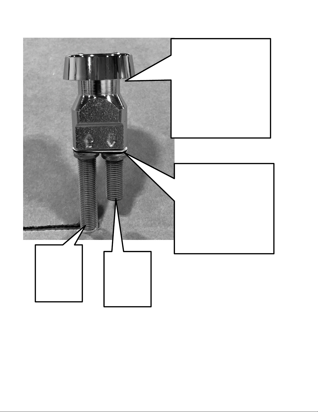
Problem: Vacuum Breaker Leaks
If it leaks from the cap:
1. Make sure the supply is
connected to the UP arrow
side. Arrows indicate direction
of flow
2. Check that the valve
diaphragm is installed and
undamaged. Loosen the cap
by hand to observe, it is a
plastic component sealed with
an O-ring.
If it leaks from the base:
The brass nipples are tapered pipe
fittings, they require Teflon tape or
thread sealant before assembly.
They are not tightened as supplied
in the fixture kit.
INLET
(UP Arrow)
Connect to
control valve
OUTLET
(DOWN Arrow)
Connect to
spray head
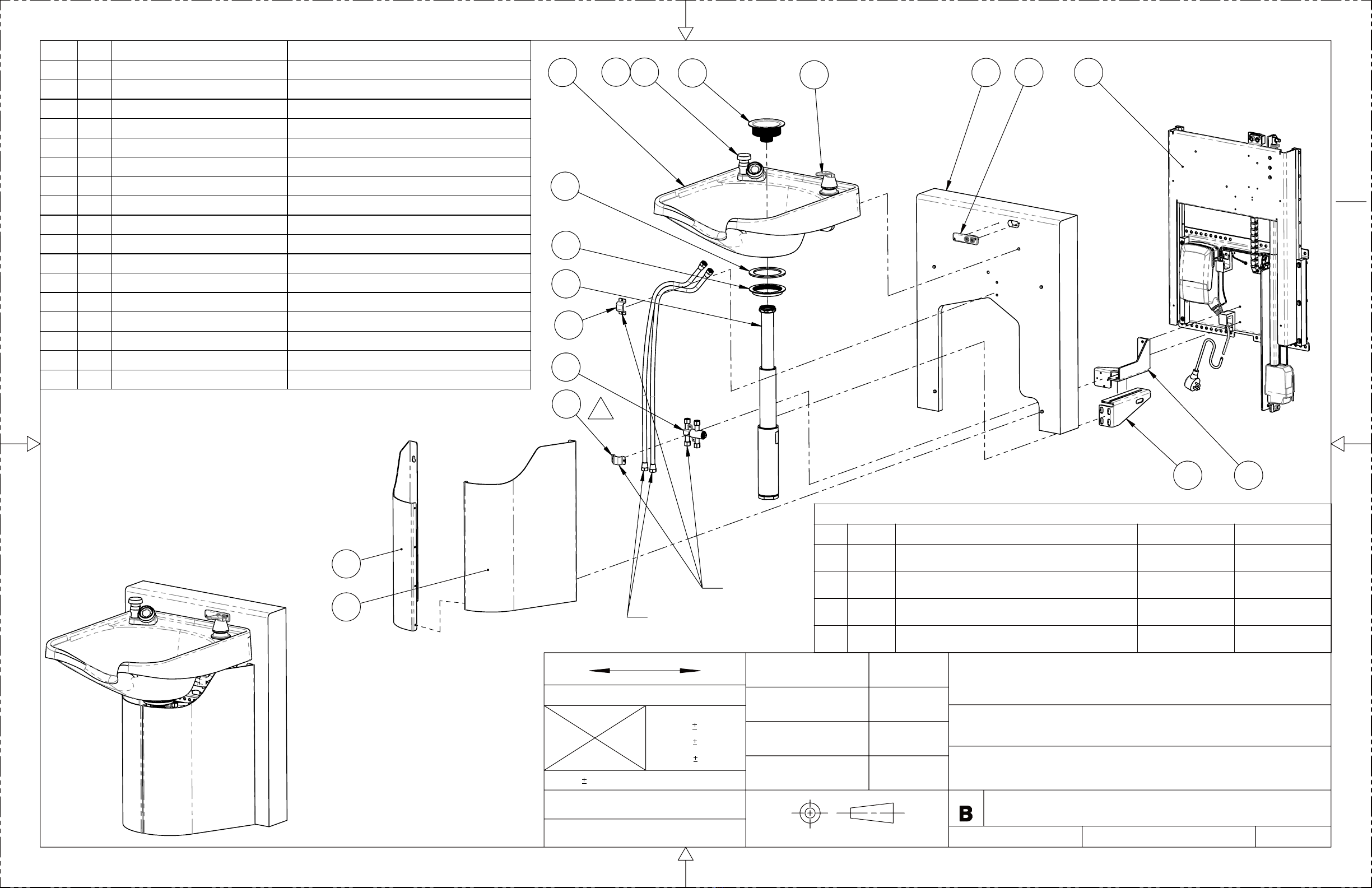
6
4 1
25
3
7
12
9
10
13 11 14
15
16
8
17
8
WATER HOSES (REF)
D
ITEM
QTY
FILE NUMBER
TITLE
1 1 40550
LIFT UNIT - E140
2 1 40340
DRAIN SUPPORT BRACKET
3 1 40360
SHROUD - LH
4 1 40420
FRONT PANEL
5 1 40460
DRAIN CLAMP BRACKET
6 1 40480
SHROUD - RH
7 1 40560
CONTROL ASSEMBLY
8 2 40180
DOUBLE HOSE CLAMP
9 1 650
FIXTURE SET
10 1
VACUUM BREAKER
SUPPLIED WITH 650
11 1
SPRAY HOSE
SUPPLIED WITH 650
12 1
T1514
TELESCOPING DRAIN - MODEL T1514
13 1
3050-2_V4
3050-2 SHAMPOO BOWL
14 1 20260
SINK BASKET STRAINER
15 1
BASKET STRAINER NUT
SUPPLIED WITH 20260
16 1
BASKET STRAINER GASKET
SUPPLIED WITH 20260
17 1
MIXING VALVE
MIXING VALVE (REF)
NOTES:
1. LOWER ITEM 9 (CLAMP) CAN BE USED IF ITEM
17 OPTION (MIXING VALVE) IS NOT SELECTED
SEE NOTE 1
REVISIONS
ZONE
REV.
DESCRIPTION
DATE
APPROVED
A
INITIAL RELEASE
4/2/2017
A.OLSON
B
ADDED MIXING VALVE
3/4/2018
A.OLSON
C
UPDATED BOM ENTRIES, ADDED SHEET 4
3/21/2018
A.OLSON
B3
D
REMOVE ITEM 20 AND USE ITEM 9, UPDATE BOM DETAILS
3/10/2020
A.OLSON
E140
DRAWING NO.
PROPRIETARY AND CONFIDENTIAL
The information contained in this drawing is sole propriety of Accessible Systems, Inc.
Any reproduction in whole or in part without written permission is strictly prohibited.
ACCESSIBLE SYSTEMS, INC.
1 OF 4
9917 13TH AVENUE NORTH - MPLS, MN 55441 PHONE: 612 . 238 . 4600
TITLE
SIZE
DRAWING NO.
DO NOT SCALE DRAWING
WWW.ADJUSTASINK.COM
DATE
DATE
DRAFTER
DESIGNER
DATE
DATE
CUSTOMER APPROVAL
CHECKER
THIRD ANGLE PROJECTION
MM
MM(INCH)
NEXT ASSY
.0
.1
0.5°
ANGLES
MATERIAL
FINISH
25.4MM=1 INCH
TOLERANCES EXCEPT AS NOTED
INCHES
.00
.01
.000
.005
03-12-17
A.OLSON
04-02-17
AJW
TELESCOPING DRAIN - AUTO
E140

34.3 "
32.5 "
TO TOP
OF BACK
PLATE
32.1 "
48.1 "
22.0 "
REFERENCE
WALL SECTION
45.8 "
12.3 "
26.4 "
E140
DRAWING NO.
PROPRIETARY AND CONFIDENTIAL
The information contained in this drawing is sole propriety of Accessible Systems, Inc.
Any reproduction in whole or in part without written permission is strictly prohibited.
ACCESSIBLE SYSTEMS, INC.
2 OF 4
9917 13TH AVENUE NORTH - MPLS, MN 55441 PHONE: 612 . 238 . 4600
TITLE
SIZE
DRAWING NO.
DO NOT SCALE DRAWING
WWW.ADJUSTASINK.COM
DATE
DATE
DRAFTER
DESIGNER
DATE
DATE
CUSTOMER APPROVAL
CHECKER
THIRD ANGLE PROJECTION
MM
MM(INCH)
NEXT ASSY
.0
.1
0.5°
ANGLES
MATERIAL
FINISH
25.4MM=1 INCH
TOLERANCES EXCEPT AS NOTED
INCHES
.00
.01
.000
.005
03-12-17
A.OLSON
04-02-17
AJW
TELESCOPING DRAIN - AUTO
E140

.55 "
THE ADJUSTABlE BACKSPLASH
REQUIRES ADEQUATE CLEARANCE TO
LIFT, ADD SPACER BLOCKS OR PANELS
BEHIND WALL MOUNT PANEL IF
TRIMWORK OR OTHER ELEMENT WILL
INTERFERE.
34 " 34 "
36 "
6 "
STYLIST WORK SPACE STYLIST WORK SPACE
PREFERRED WORK SIDE
ALTERNATE WORK SIDE,
THIS SIDE OF SINK MAY
BE CLOSER TO WALL OR
OBSTACLES IF PREFERRED
SIDE SPACE IS RESERVED
RESERVE WORK SPACE FOR SYLIST
IN SALON PLAN. IF MULTPLE SINKS
ARE BEING INSTALLED ALONG THE SAME
WALL, SPACE AT 54 " OR GREATER ON
CENTER
22.5 " MIN
16 " TYP
6.0 " MAX
CABINET WITH RECESSED AREA FOR SINK MOUNTING
THE ADJUST-A-SINK MAY
BE MOUNTED FLUSH TO A
WALL OR FRONT FACE OF CABINETS.
THE UNIT MAY ALSO BE
RECESSED FROM CABINET
FACE BY A MAXIMUM OF 6 "
E140
DRAWING NO.
PROPRIETARY AND CONFIDENTIAL
The information contained in this drawing is sole propriety of Accessible Systems, Inc.
Any reproduction in whole or in part without written permission is strictly prohibited.
ACCESSIBLE SYSTEMS, INC.
3 OF 4
9917 13TH AVENUE NORTH - MPLS, MN 55441 PHONE: 612 . 238 . 4600
TITLE
SIZE
DRAWING NO.
DO NOT SCALE DRAWING
WWW.ADJUSTASINK.COM
DATE
DATE
DRAFTER
DESIGNER
DATE
DATE
CUSTOMER APPROVAL
CHECKER
THIRD ANGLE PROJECTION
MM
MM(INCH)
NEXT ASSY
.0
.1
0.5°
ANGLES
MATERIAL
FINISH
25.4MM=1 INCH
TOLERANCES EXCEPT AS NOTED
INCHES
.00
.01
.000
.005
03-12-17
A.OLSON
04-02-17
AJW
TELESCOPING DRAIN - AUTO
E140

20.0 "
12.0 "
.75 " (TYP)
19.0 " (REF)
32.5 "
32.0 "
2.5 "
6.5 " MAX
10.0 " MIN
16.0 " MAX
MOUNT BOTH SUPPLIES
ON THE LEFT SIDE
OF THE DRAIN
8.5 "
MAX
12.0 "
MAX
12.0 "
RECOMMENDED
10. 0" MIN
19.0 " MAX
C
L
C
L
FRONT PANEL (REF)
MAINTAIN CLEARANCE
LOCATION FOR E140
MOUNTING PLATE TO
BE INSTALLED
CENTER DRAIN STUB OUT
BELOW SINK CARRIER
MOUNTING PLATE
GFCI PROTECTED
RECEPTACLE REQUIRED
NOTE: RECEPTACLE MAY
BE AVAILABE IN ADJOINING
CABINET
8.0 "
3.0 "
E140 MOUNTING PLATE
(REF)
FINISHED FLOOR (REF)
E140
DRAWING NO.
PROPRIETARY AND CONFIDENTIAL
The information contained in this drawing is sole propriety of Accessible Systems, Inc.
Any reproduction in whole or in part without written permission is strictly prohibited.
ACCESSIBLE SYSTEMS, INC.
4 OF 4
9917 13TH AVENUE NORTH - MPLS, MN 55441 PHONE: 612 . 238 . 4600
TITLE
SIZE
DRAWING NO.
DO NOT SCALE DRAWING
WWW.ADJUSTASINK.COM
DATE
DATE
DRAFTER
DESIGNER
DATE
DATE
CUSTOMER APPROVAL
CHECKER
THIRD ANGLE PROJECTION
MM
MM(INCH)
NEXT ASSY
.0
.1
0.5°
ANGLES
MATERIAL
FINISH
25.4MM=1 INCH
TOLERANCES EXCEPT AS NOTED
INCHES
.00
.01
.000
.005
03-12-17
A.OLSON
04-02-17
AJW
E140 ROUGH-IN
E140

Adjust-A-Sink® E140 System by Accessible Systems Inc. | Minneapolis, MN | 612-238-4600 | www.adjustasink.com
20 of 25
E140 SERIES
TWO YEAR LIMITED WARRANTY
Adjust-a-Sink E140 Series products from Accessible Systems, Inc. have been manufactured
under the highest standards of quality and workmanship. Accessible Systems, Inc. warrants
to the original end-user purchaser this product to be free from defects in material and
workmanship during normal use for two (2) years from date of purchase. A replacement for
any defective part will be supplied for installation by you. Defects or damage caused by the
use of other than genuine Adjust-a-Sink parts are not covered by this warranty. This
warranty shall be effective from the date of purchase shown on the purchaser’s receipt.
This warranty is valid for the original purchaser only and excludes product damage due to
installation error, product abuse, product misuse, wear and tear or stains, whether performed
by a contractor, service company, or end user. Accessible Systems, Inc. will not be
responsible for labor charges, and/or damage incurred in installation, repair or replacement,
nor for incidental, indirect, special, or consequential damages, including without limitation,
damage to, or loss of use of, any equipment, lost sales or profits or delay or failure to perform
this warranty obligation.
This warranty is void if this product is installed incorrectly or in an improper environment,
overloaded, misused, abused, or altered in any manner, or not used under normal operating
conditions or not in accordance with accompanying or relevant instructions, packaging or
labels.
Accessible Systems, Inc. will advise you of the procedure to follow in making warranty
claims. Contact technical support at 612-238-4600 or visit www.adjustasink.com for
assistance diagnosing the problem. Product serial numbers and proof of purchase date are
required.
Table of contents
Other Adjust-a-Sink Plumbing Product manuals

Popular Plumbing Product manuals by other brands


SFA
SFA SANI 2 installation instructions

resideo
resideo Braukmann BA295STN installation instructions

American Standard
American Standard Shower Systems 1660.525 Specification sheet

Newport Brass
Newport Brass 1-339 installation instructions

Kohler
Kohler K-T45115 Installation and care guide

Axor
Axor Terrano 37136XX1 Specification sheet

Sterling Plumbing
Sterling Plumbing 11850 Specifications

Kohler
Kohler SUMMON K-24147T-7 Installation & operating instructions

Moen
Moen 64920 manual

Hansgrohe Axor
Hansgrohe Axor Bouroullec 19010000 Instructions for use/assembly instructions

BELLOSTA
BELLOSTA romina 0301/40/26/C installation instructions

Grohe
Grohe Ondus 36 083 Assembly instructions