Adler MMA-175 User manual


PARAMETERS:
Model
MMA-175
MMA-195
MMA-220
Power
1 phase AC
230V / 50Hz
1 phase AC
230V / 50Hz
1 phase AC
230V / 50Hz
Max. Power
Consumption
6,1kW
7,2kW
8,7kW
Welding Current Range
20-160A
20-190A
20-220A
Diameter of Electrodes
1,6÷4,0
1,6÷5,0
1,6÷5,0
Rated Output Amperage
28A
36A
39A
Rated Output Voltage
26.4V
27.6V
28,8V
Duty Cycle
60%@160A
60%@190A
60%@220A
Efficiency
85%
85%
85%
Isolation Class
H
H
H
Protection Class
IP21S
IP21S
IP21S
Weight
3.7kg
3.7kg
4.3kg
Dimensions
290x105x200mm
290x105x200mm
280x115x119mm

Warnings:
Electric Shock
Danger of Welding Fumes
Danger of Explosion
Danger of UV Radiation
Eye Protection and Face Shield is Compulsory
Personal Protection is Compulsory
Wearing of Protective Gloves is Compulsory
Users of vital electrical and electronic apparatus must never use the
machine
Non-Ionizing Radiation
separation of electrical and electronic appliances for refuse collection. The user is
not allowed to dispose of these appliances as solid, mixed urban refuse, and must
do it through authorized refuse collection centers

WARNING: READ THE MANUAL CAREFULLY BEFORE USING THE WELDING MACHINE
This welding machine conforms to technical product standards for exclusive use in an industrial
environment and for professional purposes.
1 . GENERAL SAFETY CONSIDERATIONS FOR ARC WELDING
The operator should be properly trained to use the welding machine safely and should be informed about the
risks related to arc welding procedures, the appropriate protection measures and emergency procedures.
Danger of Electric Shock:
Avoid direct contact with the welding circuit: the no-load voltage supplied by the welding machine can be dangerous
under certain circumstances.
- When the welding cables are being connected or checks and repairs are carried out, the welding machine should be
switched off and disconnected from the power supply outlet.
- Switch off the welding machine and disconnect it from the power supply outlet before replacing consumable torch
parts.
- Make the electrical connections and installation according to the safety rules and legislation in force.
- The welding machine should be connected only and exclusively to a power source with the neutral lead connected
to earth.
- Make sure that the power supply plug is correctly connected to the earth protection outlet.
- Do not use the welding machine in damp or wet places and do not weld in the rain.
- Do not use cables with worn insulation or loose connections.
- Always wear dry protection gloves and clothes
- Never touch electric parts with bare hands
- Make sure your position when welding is safe and comfortable.
- Make sure you are properly isolated from the floor and from the working place.
Poisonous fumes, danger of explosion and fire:
- Do not weld on containers or piping that contains or has contained flammable liquid or gaseous products.
- Do not operate on materials cleaned with chlorinated solvents or near such substances.
- Do not weld on containers under pressure.
- Remove all flammable materials (e.g. wood, paper, rags etc.) from the working area.
- Provide adequate ventilation or facilities for the removal of welding fumes near the arc; a systematic approach is
needed in evaluating the exposure limits for the welding fumes, which will depend on their composition, concentration
and the length of exposure itself.
- Keep the gas bottle (if used) away from heat sources, including direct sunlight
Radiation can be harmful for your eyes and skin!
- Use adequate electrical insulation with regard to the electrode, the work piece and any (accessible) earthed metal
parts in the vicinity. This is normally achieved by wearing gloves, shoes, head coverings and clothing designed for this
purpose and by using insulating platforms or mats.

- Always protect your eyes with proper filter, mounted on masks or use helmets. Use the relative fire-resistant clothing
and welding gloves without exposing the skin to the ultraviolet and infrared rays produced by the arc; the protection
must extend to other people who are near the arc by screens or nonreflective sheets.
- Always isolate electrode from welded object and possible grounded metal parts nearby.
Electromagnetic Radiation:
- The flow of the welding current generates electromagnetic fields (EMF) around the welding circuit.
Electromagnetic fields can interfere with certain medical equipment (e.g. pace-makers, respiratory equipment, metallic
prostheses etc.). Adequate protective measures must be adopted for persons with these types of medical apparatus.
Non-Ionizing Radiation:
This welding machine conforms to technical product standards for exclusive use in an industrial environment for
professional purposes. It does not assure compliance with the basic limits relative to human exposure to
electromagnetic fields in the domestic environment.
Extra precautions:
- WELDING OPERATIONS:
- in environments with increased risk of electric shock
- in confined spaces
- in the presence of flammable or explosive materials
MUST BE evaluated in advance by an “expert supervisor” and must always be carried out in the presence of other
people trained to intervene in emergencies.
The operator MUST NOT BEALLOWED to weld in raised positions unless safety platforms are used.
- VOLTAGE BETWEEN ELECTRODE HOLDERS OR TORCHES:
working with more than one welding machine on a single piece or on pieces that are connected electrically may
generate a dangerous accumulation of no-load voltage between two different electrode holders or torches, the value
of which may reach double the allowed limit. An expert coordinator must measure the apparatus to determine any
risks and apply suitable protection measures.
Residual Risks
- IMPROPER USE: it is hazardous to use the welding machine for any work other than that for which it was designed
(e.g. de-icing mains water pipes).
- Do not use the handle to hang the welding machine.
- In case of any malfunction, follow instructions step by step.
- If you cannot solve a problem by yourself, please, contact authorized service provider.
- Welding machine must be connected to the power supply equipped with the earth leakage circuit breaker.

2 . GENERAL INFORMATION
2.1 INTRODUCTION
- This welding machine is a power source for arc welding, made specifically for direct current (DC).
The specific characteristics of this regulation system (INVERTER), i.e. high speed and precise regulation, mean the
welding machine gives excellent results when welding with coated electrodes (rutile, acid, basic).
Regulation with the “inverter” system at the input of the power supply line (primary) means there is a drastic reduction
in the volume of both the transformer and the levelling reactance. This allows the construction of a welding machine
with extremely reduced weight and volume, enhancing its advantages of easy handling and transportation.
2.2 OPTIONALACCESSORIES:
- MMA welding Kit.
3. TECHNICAL DATA
DATA PLATE
The most important data regarding use and performance of the welding machine are summarized on the rating plate
and have the following meaning:
1 –Protection class
2 –Symbol of the power supply line
3 –Type of the welding process
4 –Construction diagram
5 –Safety norm
6 –Serial number
7 –Parameters of the welding circuit
8 –Power supply line specifications
9 - Size of delayed action fuses to be used to protect the power line.
10 –Symbols referring to safety regulations,
The data plate shown above is an example to give the meaning of the symbols and numbers; the exact values of
technical data for the welding machine in your possession must be checked directly on
the data plate of the welding machine itself.
10
9
6
7
8
5
4
3
1
2

4. DESCRIPTION OF WELDING MACHINE
4.1 The unit is comprised of power modules which have been developed on a specially printed circuit designed to
maximize reliability and reduce maintenance.
1- Power supply input (1~), rectifier group and balancing capacitors.
2- Transistors and drivers switching bridge (IGBT). It turns the mains rectified voltage into high frequency alternate
voltage and permits power regulation according to the current/ voltage of the weld to be done.
3- High frequency transformer: the primary windings are fed by the voltage converted by Block 2, it adapts the voltage
and the current to the values required by the arc welding procedure and, simultaneously, isolates the welding circuit
from the mains.
4- Secondary rectifier bridge with inductance: this changes the alternate voltage/current supplied by the secondary
windings into continuous current/voltage at a low wave-length.
5- Electronic and regulation board: this instantly checks the value of the welding current against that selected by the
user, it modulates the commands of the IGBT drivers, which control regulation, determines the dynamic response of
the current while the electrode melts (instantaneous short circuits), and supervises the safety systems.
4.2 Panels
Front Back
1) Negative quick plug (-) to connect welding cable
2) Positive quick plug (+) to connect welding cable
3) Welding current display
4) Power supply control –the machine is ready to work
5) Handle
6) Thermal protection control; mains over/undervoltage protection; ANTI STICK protection (preventing the
electrode from sticking to the welded material)
7) Welding current knob
8) ON/OFF switch
9) Power supply cable 230V
10) Fan

5. INSTALLATION
WARNING! CARRY OUT ALL INSTALLATION OPERATIONS AND ELECTRICAL CONNECTIONS
WITH THE WELDING MACHINE COMPLETELY SWITCHED OFF AND DISCONNECTED FROM THE
POWER SUPPLY OUTLET. THE ELECTRICAL CONNECTIONS MUST BE MADE ONLY AND
EXCLUSIVELY BY AUTHORISED OR QUALIFIED PERSONNEL.
5.1 Preparation
Unpack the welding machine, assemble the separate parts from the package.
5.1.1 Assembling the return cable-clamp
5.1.2 Assembling the welding cable-electrode holder clamp
5.2 HOW TO LIFT THE WELDING MACHINE
All the welding machines described in this handbook should be lifted using the handle or strap (if provided) for the
particular model.
5.3 POSITION OF THE WELDING MACHINE
Choose the place to install the welding machine so that the cooling air inlets and outlets are not obstructed
(forced circulation by fan, if present); at the same time make sure that conductive dusts, corrosive vapors,
humidity etc. will not be sucked into the machine. Leave at least 250mm free space around the welding machine.
WARNING! Position the welding machine on a flat surface with sufficient carrying capacity for its weight, to
prevent it from tipping or moving hazardously.

5.4 CONNECTION TO THE MAIN POWER SUPPLY
- Before making any electrical connection, make sure the rating data of the welding machine correspond to the mains
voltage and frequency available at the place of installation.
- The welding machine should only be connected to a power supply system with the neutral conductor connected to
earth.
- the machine can be connected to a mains outlet fitted with fuses or an automatic circuit-breaker; the special earth
terminal should be connected to the earth conductor (yellow-green) of the power supply line.
WARNING! Failure to observe the above rules will make the (Class 1) safety system installed by the
manufacturer ineffective with consequent serious risks to persons (e.g. electric shock) and objects
(e.g. fire).
5.5 CONNECTION OF THE WELDING CABLES
WARNING! BEFORE MAKING THE FOLLOWING CONNECTIONS, MAKE SURE THE WELDING
MACHINE IS SWITCHED OFF AND DISCONNECTED FROM THE POWER SUPPLY OUTLET.
5.5.1 MMA WELDING
Almost all coated electrodes are connected to the positive pole (+) of the power source; as an exception to the
negative pole (-) for acid coated electrodes.
Turn the welding cable connectors right down into the quick connections (if present), to ensure a perfect electrical
contact; otherwise the connectors will overheat, resulting in the rapid deterioration and loss of efficiency.
- The welding cables should be as short as possible.
- Do not use metal structures which are not part of the workpiece to substitute the return cable of the welding current:
this could jeopardize safety and result in poor welding.
6. WELDING
- It is most important to refer to the manufacturer’s instructions indicated on the stick electrode packaging. This will
indicate the correct polarity of the stick electrode and the most suitable current.
- The electrode in use and the type of the joint to be carried out - see below the currents corresponding to various
electrode diameters:
Diameter
ø 1.6
ø 2.5
ø 3.2
ø 4.0
ø 5.0
Welding current
30-80A
60-100A
80-140A
140-170A
170-250A
The mechanical characteristics of the welded join are also determined by the other welding parameters i.e. arc length,
working rate and position, electrode diameter and quality (to store the electrodes correctly, keep them in a dry place
protected by their packaging or containers).
6.1.1 Procedures
- Holding the mask IN FRONT OF THE FACE, strike the electrode tip on the workpiece as if you were striking a match.
This is the correct strike-up method.
- WARNING: do not hit the electrode on the workpiece, this could damage the electrode and make strike-up difficult.
- As soon as arc is ignited, try to maintain a distance from the workpiece equal to the diameter of the electrode in use.
All the time keep this distance as even as possible. Remember that the angle of the electrode as it advances, should

be of 20-30 grades.
- At the end of the weld bead, bring the end of the electrode backward, in order to fill the weld crater, quickly lift the
electrode from the weld pool to extinguish the arc.
7. MAINTENANCE
WARNING! BEFORE CARRYING OUT MAINTENANCE OPERATIONS MAKE SURE THE WELDING
MACHINE IS SWITCHED OFF AND DISCONNECTED FROM THE MAIN POWER SUPPLY.
7.1 EXTRAORDINARY MAINTENANCE MUST ONLY BE CARRIED OUT BY TECHNICIANS WHO ARE EXPERT OR
QUALIFIED IN THE ELECTRIC-MECHANICAL FIELD
Checks inside the welding machine while it is on, may cause serious electric shock due to the direct contact with live
parts and/or injury due to direct contact with moving parts.
- Inspect the welding machine regularly, with a frequency depending on use and the dustiness of the environment, and
remove the dust deposited on the transformer, reactance and rectifier using a jet of dry compressed air (max. 10bar).
- Do not direct the jet of compressed air on the electronic boards; these can be cleaned with a very soft brush or
suitable solvents.
- At the same time make sure the electrical connections are tight and check the wiring for the insulation damage.
- At the end of these operations, re-assemble the panels of the welding machine and screw the fastening screws right
down.
- Never carry out welding operations while the welding machine is open.
- After having carried out maintenance or repairs, restore the connections and wiring as they were before, making sure
they do not come into contact with moving parts or parts that can reach high temperatures. Tie all the wires as they
were before, be careful to keep the high voltage connections of the primary transformer separate from the low voltage
ones of the secondary transformer.
Use original washers and screws when closing the casing.
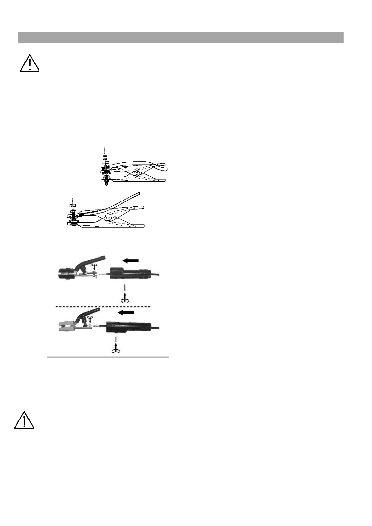
7.2 Maintenance of cables and clamps
- Do not touch hot objects with the cable and the clamp.
- Periodically check leak tightness of gas connections.
- Check contacts and connections of the welding cables and the clamps.
- Before each operation, check the electrodes and the clamps.
8. TROUBLESHOOTING
IN CASE OF UNSATISFACTORY FUNCTIONING, BEFORE SERVICING MACHINE OR REQUESTING
ASSISTANCE, CARRY OUT THE FOLLOWING CHECK:
- Check that the welding current, which is regulated by the potentiometer with a graduated amp scale, is correct for the
diameter and electrode type in use.
- Check that when general switch is ON, the corresponding lamp is ON too. If this is not the case then the problem is
located on the mains (cables, plugs, outlets, fuses, etc.).
- Check that the yellow led (ie. thermal protection interruption - either over or undervoltage or short circuit) is not lit.
- Check that the nominal intermittence ratio is correct. In case there is a thermal protection interruption, wait for the
machine to cool down, check if the fan is working properly.
- Check the mains voltage: if the value is too high or too low the welding machine will be stopped.
- Check that there is no short-circuit at the output of the machine.
- Check that all connections of the welding circuit are correct, particularly that the work clamp is well attached to the
workpiece, with no interfering material or surface-coverings (ie. Paint).
- Protective gas must be of appropriate type (Argon 99.5%) and quantity.

In case any of the above does not help you to start the welding machine, please, contact the supplier or authorized
service before you dispatch the machine for a repair.
This manual suits for next models
2
Table of contents
Other Adler Welding System manuals
Popular Welding System manuals by other brands

SIP
SIP T1400 manual

Schweißkraft
Schweißkraft CRAFT-TIG 201 DC P PULSE operating instructions

EWM
EWM Taurus 355 Basic TDM operating instructions

Lincoln Electric
Lincoln Electric HANDYMIG 170I Operator's manual

EWM
EWM Tetrix XQ 230 puls DC Comfort 3.0 operating instructions

Chicago Electric
Chicago Electric HOBBY ARC WELDER Assembly and operating instructions