Admiral 62cc User manual

62CC GASOLINE ENGINE
INSTRUCTION MANUAL

ENGLISH
Note:ĞĨŽƌĞŽƉĞƌĂƟŶŐƌĞĂĚƚŚĞŝŶƐƚƌƵĐƟŽŶŵĂŶƵĂůƚŽďĞĐŽŵĞĨĂŵŝůŝĂƌǁŝƚŚƚŚĞĨĞĂƚƵƌĞƐ
ŽĨƚŚĞƉƌŽĚƵĐƚ
Warning: tĞƌĞĐŽŵŵĞŶĚƐŽƉĞƌĂƟŽŶŽĨƚŚŝƐŝƚĞŵďLJĐŚŝůĚƌĞŶŽůĚĞƌƚŚĂŶϭϰLJĞĂƌƐdŚŝƐ
ƉƌŽĚƵĐƚŝƐŶŽƚĂƚŽLJKǁŶĞƌƐĂƌĞƌĞƐƉŽŶƐŝďůĞĨŽƌƚŚĞƐĂĨĞŽƉĞƌĂƟŽŶŽĨƚŚĞĞŶŐŝŶĞƵƐĞ
ĚŝƐĐƌĞƟŽŶĂƚĂůůƟŵĞƐ
Beware: ƌŽƚĂƟŶŐƉƌŽƉĞůůĞƌŝƐĚĂŶŐĞƌŽƵƐĚŽŶŽƚƚŽƵĐŚŽƌĂůůŽǁĂŶLJŽďũĞĐƚƚŽŵĂŬĞ
ĐŽŶƚĂĐƚǁŝƚŚƉƌŽƉĞůůĞƌŽŶŽƚĐƌŽƵĐŚŽǀĞƌƚŚĞĞŶŐŝŶĞǁŚŝůĞŝŶŽƉĞƌĂƟŽŶ
ĂƵƟŽŶDŽĚĞůĞŶŐŝŶĞƐŐĞŶĞƌĂƚĞŚĞĂƚĚŽŶŽƚƚŽƵĐŚĂŶLJƉĂƌƚŽĨƚŚĞĞŶŐŝŶĞƵŶƟůŝƚŚĂƐ
ĐŽŽůĞĚƐĞƌŝŽƵƐďƵƌŶƐŵĂLJƌĞƐƵůƚ
dŚŝƐƉƌŽĚƵĐƚŵƵƐƚŶŽƚďĞĚŝƐƉŽƐĞĚǁŝƚŚ
ŚŽƵƐĞŚŽůĚǁĂƐƚĞ/ƚŝƐƚŚĞƵƐĞƌƐƌĞƐƉŽŶ-
ƐŝďŝůŝƚLJƚŽĚŝƐƉŽƐĞŽĨĞŶŐŝŶĞĐŽŵƉŽŶĞŶƚƐ
ǁŝƚŚĂĚĞƐŝŐŶĂƚĞĚƌĞĐLJĐůŝŶŐƐĞƌǀŝĐĞZĞ-
ĐLJĐůŝŶŐŚĞůƉƐĐŽŶƐĞƌǀĞŶĂƚƵƌĂůƌĞƐŽƵƌĐĞƐ
ĂŶĚĞŶƐƵƌĞƐĂŚĞĂůƚŚLJĞŶǀŝƌŽŶŵĞŶƚ&Žƌ
ŵŽƌĞŝŶĨŽƌŵĂƟŽŶĐŽŶĐĞƌŶŝŶŐƌĞĐLJĐůŝŶŐ
ƉůĞĂƐĞĐŽŶƚĂĐƚLJŽƵƌůŽĐĂůĐŝƚLJŽƌĚŝŶĂŶĐĞ
ŽĸĐĞLJŽƵƌǁĂƐƚĞŵĂŶĂŐĞŵĞŶƚƐĞƌǀŝĐĞ
ŽƌƚŚĞƉůĂĐĞŽĨƉƵƌĐŚĂƐĞ
dŚŝƐƉƌŽĚƵĐƚĐŽŵƉůŝĞƐǁŝƚŚh^ĂŶĚh
ĚŝƌĞĐƟǀĞƐƌĞŐĂƌĚŝŶŐĞƐƐĞŶƟĂůƉƌŽƚĞĐ-
ƟŽŶƌĞƋƵŝƌĞŵĞŶƚƐŽĨĞůĞĐƚƌŽŵĂŐŶĞƟĐ
ĐŽŵƉĂƟďŝůŝƚLJĞĐůĂƌĂƟŽŶŽĨŽŶĨŽƌ-
ŵŝƚLJŝƐĂǀĂŝůĂďůĞ
ENVIRONMENTAL CONCERNS:
DECLARATION OF CONFORMITY
SAFETY INSTRUCTIONS

ENGLISH
INTRODUCTION
INSTALLING THE ENGINE
WARNING:
-
ge.
A: Choke Lever
C: Fuel Inlet
ŽŶŐƌĂƚƵůĂƟŽŶƐfŽƌƉƵrĐŚĂƐŝŶŐŽŶĞŽĨŽƵƌexĐŝƟŶŐŶeǁgĂƐĞŶŐŝŶĞƐdŚĞŝŶŶŽǀĂƟǀĞgĂƐĞŶŐŝŶĞƐĞƌŝĞƐ
ĞŶƐƵrĞĂŚĂƐƐůĞ-frĞĞedžƉĞƌŝĞŶĐĞǁŝƚŚŽƵƚůŽƐƐŽĨƉĞƌfŽƌŵĂŶĐĞŽƌĚƵrĂďŝůŝƚLJƚŚrŽƵŐŚcareĨƵůĚĞƐŝŐŶĂŶĚ
tĞƐƟŶŐdŚŝƐŵĂŶƵĂůǁŝůůŐƵŝĚĞLJŽƵƚŚrŽƵŐŚƚŚĞƐŝŵƉůĞƐteƉƐtŽLJŽƵƌƐƵĐĐĞƐƐǁŚĞŶcareĨƵůůLJrĞĂĚĂŶĚ
followĞĚ
DŽƵŶƟŶŐƚŚĞϲϮŝƐƐŝŵƉůĞǁŝƚŚƚŚĞŽǀĞƌĂůůĚŝŵĞŶƐŝŽŶƐĚĞƐŝŐŶĞĚƚŽĮƚĐƵƌƌĞŶƚŐŝĂŶƚͲƐĐĂůĞŽīĞƌŝŶŐƐ
ĞĐĂƵƐĞŝƚƐƉƌŽƉĞůůĞƌĂŶĚŵƵŋĞƌŵŽƵŶƚŶŐĚŝŵĞŶƐŝŽŶƐŵĂƚĐŚŽƚŚĞƌƉŽƉƵůĂƌϱϬĐĐĂŶĚϲϬĐĐĞŶŐŝŶĞƐ
ƚŚĞϲϮŝƐĂŐŽŽĚĮƚŝŶŵĂŶLJĞdžŝƐƚŶŐϱϬʹϲϬĐĐĂŝƌĨƌĂŵĞƐ

4
ENGLISH
CONNECTING THE THROTTLE LINKAGE
16mm (5/8 in)
1. hƐĞƚŚĞƉƌŽǀŝĚĞĚďĂůůͲůŝŶŬƚŽĂƩĂĐŚƚŚĞƚŚƌŽƩůĞ
2.
3.
4.
5.
6.
the pushrod where it meets this hole.
7. Using pliers, bend the pushrod so there is a 90° bend at the mark.
8. Using a pushrod keeperƐĞĐƵre the pushrod in the servo arm.
9.
10.
CONNECTING THE ELECTRONIC IGNITION
BASELINE NEEDLE SETTINGS
-
gine are 1.5 turns out for the high-speed
needle, and 1.75 turns out for the low-
speed needle.
seat gently— do not forĐĞƚŚĞŵƚŚŝƐĐould
damage the needles or Đarburetor body.
Open the needles the number of turns
listed above.
Low speed needle
High speed needle

5
ENGLISH
FUEL
To properly mix the fuel, add 4.0 oz of high quality 2-stroke oil to one gallon (or 32 mL of oil to one
liter) of 87–93 octane fuel.
We tested primarily with Red Line two-stroke oil. Other high-quality two-stroke oils will also work
well. Mixtures as rich as 25:1 are acceptable.
ENGINE BREAK-IN
-
develop a good seal.
Perform the break-in process with the engine mounted on your airplane. There is no need to
Use a lightly loaded break-in prop to begin your break-in process (22 x 10 or 23 x 9)
• First tank of fuel: Run the engine on the
-
• Second tank of fuel: Do not run at full
sure to mix in some cooling dives and lower-
• Third tank of fuel: Fly the engine at high
up to one minute. This will help the piston
ring and cylinder to expand and contract,
helping the breaking-in process.
• Fourth tank of fuel: Select one of the
recommended propellers for normal opera-
STARTING AND RUNNING THE ENGINE
&ƵĞůƐŚŽƵůĚďĞĮůtered in your fueling system before it enters your model. Failure to prŽƉĞƌůLJĮůter
/ƚŝƐĐƌŝƟĐĂůƚŽƚŚĞƉƌŽƉĞƌŽƉĞƌĂƟŽŶŽĨLJŽƵƌϲϮĐĞŶŐŝŶĞƚŚĂƚLJŽƵƵƐĞƚŚĞŝŶĐůƵĚĞĚĮůƚĞƌĞĚĐůƵŶŬ
ƚŚĞĨƵĞůďĞĨŽƌĞŝƚƌĞĂĐŚĞƐLJŽƵƌĞŶŐŝŶĞĐĂŶŝŶƚƌŽĚƵĐĞĐŽŶƚĂŵŝŶĂƟŽŶŝŶƚŽƚŚĞĨƵĞůƐLJƐƚĞŵ

6
ENGLISH
1. Power ON the radio system but leave the
engine power system OFF.
2. Close the choke valve on the carburetor.
3. -
4. Power ON the engine power system.
5. -
pression. Flip the propeller through com-
6. Open choke valve on the carburetor and
7. Let the engine run at high idle for 30 se-
conds to stabilize the temperatures.
8.
If the engine doesn’t start quickly
9. If the engine appears not to have any fuel,
repeat the priming procedure in step 2—5.
• Check for fuel systems problems. Are there
any holes in the fuel lines (inluding the
clunk line inside the fuel tank) or other pos-
sible sources of air leaks?
If the engine runs
•
charged
1. Remove the spark plug.
2. Cover the cylinder head with a cloth or
paper towel and turn the propeller over to
If you suspect the engine is
expel the excess fuel.
3.
again.
If the engine cannot be turned over easily:
TROUBLESHOOTING GUIDE
• Check and use a new spark plug if needed.
Remove the spark plug and reinstall it into
-
er system ON, move the sensor magnet past
-
nually moving the sensor past the magnet).
You should be able to either see the spark
The engine RPM needs to exceed 180 RPM
plug. Make sure to rapidly move the magnet
past the sensor when checking for proper
• Check fuel lines for damage or kinks. If any
of the lines are restricted, the fuel system
will likely not operate. Clean and intact
properly.
•
turning the engine over.
• Check that the carburetor is correctly
installed and that all gaskets are intact and
undamaged.
•
from any bends or blockages.
If the engine does not start:
A possible cause is the piston is seized in the cylinder: loosen and unscreǁƚŚĞŵƵŋĞƌďŽůƚƐ
Visually inspect the piston and cylinder through the exhaust port.
If there are excessive/deep scratches or grooves in the piston, please contact your local
ƐƵƉƉůŝĞƌĐƵƐƚŽŵĞƌƐĞƌǀŝĐĞĨŽƌŵŽƌĞŝŶĨŽƌŵĂƟŽŶ
Repair of a seized piston/cylinder is mechanical and should not be atempted.

7
ENGLISH
SPECIFICATIONS
Spark Plug Cap
Propeller Bolt
Dimensions
Engine
Mount Di-
mensions
Disp 62cc
Bore 46.0 mm (1.80 in)
Stroke 37.0 mm (1.50 in)
Cylinder Nikasil plated Aluminum
Plug type CM-6
Engine Weight 1483 g (52.3 oz)
M5
1.5 H
1.75 L
PROPELLER SPECIFICATIONS
Propeller Typical Ground RPM
Menz (wood) 22 x 10“ 7000
Menz (wood) 23 x 8“ 7000
Mejzlik (CF) 23 x 8“ 7100
Mejzlik (CF) 23 x 10“ 6900
Mejzlik (CF) 24 x 10“ 6400

8
ENGLISH
EXPLODED VIEW

9
ENGLISH
PARTS LIST
#
1Walbro Carburetor 62
2Front Prop Washer 62
3Rear Prop Washer 62
4Prop Bolt Set (4) M5 x 45 62
5Prop Drive Retaining Bolt 62
6Prop Driver with Key 62
7
8
Front Crankcase with Bearings 62
9
10
11 Crankcase Align Keys (2) 62
12
13
14
15 Conrod Assembly 62
16 Conrod Lower Bearing 62
17 Conrod Retaining Screw 62
18 Piston Pin with Clips 62
19 Piston 62
20 Piston Ring 62
21 Cylinder Gasket 62
22 Crankcase Bolt Set 62
23 Exhaust Flange Gasket (2) 62
24 Cylinder Head 62
25 Rear Crankcase 62
26 Reed Cage Gasket Set 62
27 Aluminum Reed Cage 62
28 Reed Mount Strap (2) 62
29 Intake Reeds (2) 62
30
31
32 Carburetor Gasket Set (3) 62
33 Engine Gasket Set 62
34
35 Carburetor Velocity Stack 62
36 Spark Plug CM6
WŽŽĚƌƵīKey (2) 62
/ŐŶŝƟŽŶWŝĐkup Magnet 62
Front CrankshaŌďĞĂƌŝŶŐϲϮ
Rear CrankshaŌĞĂƌŝŶŐϲϮ
CrankshaŌϲϮ
CrankshaŌstuīer Assembly 62
Carburetor MounƟŶŐůŽĐŬϲϮ
Carburetor MounƟŶŐŽůƚ^et 62
/ŐŶŝƟŽŶ^ĞŶƐŽƌĂŶĚDŽƵnt Set 62
This manual suits for next models
1
Table of contents
Popular Engine manuals by other brands
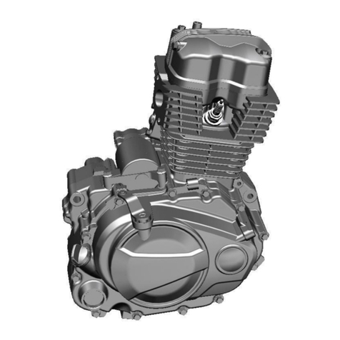
VM
VM CBF 125 SERVICE MANUAL AND EFI DIAGNOSTIC

Generac Power Systems
Generac Power Systems GN - 320 owner's manual

Volvo Penta
Volvo Penta 13L Operator's manual

Erreka
Erreka SENA installation instructions

Iveco
Iveco Marine Diesel Engines Installation handbook
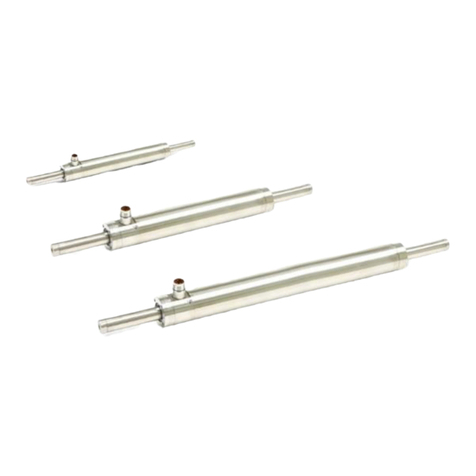
LinMot
LinMot PS01-48x240F-EX-E installation guide


