ADS-tec MCR5000 User manual
User Manual
Industrial PCs
MCR5000
Version 1.3

Industrial PCs MCR5000
2 © ads-tec GmbH • Raiffeisenstr.14 • 70771 Leinfelden-Echterdingen
Product Portfolio
Copyright
©ads-tec GmbH
Raiffeisenstr.14
D-70771 Leinfelden-Echterdingen
Germany

Industrial PCs MCR5000
© ads-tec GmbH • Raiffeisenstr.14 • 70771 Leinfelden-Echterdingen 3
INDEX
ABOUT US.......................................................................................................................................... 5
1REMARKS ................................................................................................................................. 6
1.1 RELEVANT DEVICE DOCUMENTATION................................................................................................6
1.2 DESCRIPTION OF THE WARNING SYMBOLS USED IN THIS GUIDE...............................................................6
1.3 DATA,IMAGES,AMENDMENTS AND VARIATIONS.................................................................................6
1.4 TRADEMARKS ............................................................................................................................6
1.5 COPYRIGHT ..............................................................................................................................7
1.6 ENVIRONMENTAL CONDITIONS .......................................................................................................7
1.7 STANDARDS..............................................................................................................................8
1.8 SCOPE OF DELIVERY....................................................................................................................9
2OPERATING INSTRUCTIONS ....................................................................................................... 10
2.1 OPERATING LOCATION...............................................................................................................10
2.2 DAMAGES DUE TO IMPROPER USE.................................................................................................10
2.3 WARRANTY /REPAIRS...............................................................................................................11
2.4 TREATMENT AND DISPOSAL OF LITHIUM BATTERIES ...........................................................................11
2.5 SAFETY INSTRUCTIONS ..............................................................................................................11
3ASSEMBLY ..............................................................................................................................12
3.1 OVERALL DEVICE DIMENSIONS ....................................................................................................12
3.2 ORDER OF INSTALLATION ...........................................................................................................13
4COMMISSIONING..................................................................................................................... 23
4.1 AVAILABLE INTERFACES..............................................................................................................23
4.2 CABLE INSTALLATION ................................................................................................................24
4.3 READINESS FOR OPERATION CHECKS.............................................................................................24
4.4 STATUS DISPLAYS.....................................................................................................................24
5INTERFACES............................................................................................................................ 25
5.1 230 VAC POWER SUPPLY ..........................................................................................................25
5.2 USB CONNECTIONS ..................................................................................................................26
5.3 SIM CARD READER ACCORDING TO ISO 7816 ................................................................................. 26
5.4 IEEE1394 FIREWIRE 4-PIN CONNECTION (WITHOUT POWER) ............................................................27
5.5 NETWORK CONNECTION (RJ45) ..................................................................................................27
5.6 COM (RS232) SERIAL INTERFACE...............................................................................................28
5.7 OPTIONAL RADIO NETWORK CARD.................................................................................................28
5.8 DVI INTERFACE .......................................................................................................................29
5.9 AUDIO L/R.........................................................................................................................30
6DRIVES.................................................................................................................................. 31
6.1 HARD DRIVES /COMPACT FLASH DRIVE (IDE INTERFACE) ...................................................................31
6.2 DVD DRIVE /INTEGRATED MODEL (NOTEBOOK) ...............................................................................31
6.3 EXTERNAL DRIVES ....................................................................................................................32
7TECHNICAL DETAILS ................................................................................................................. 33
7.1 COMPUTER DATA...................................................................................................................... 33

Industrial PCs MCR5000
4 © ads-tec GmbH • Raiffeisenstr.14 • 70771 Leinfelden-Echterdingen
7.2 GENERAL DATA........................................................................................................................ 33
8SERVICE AND SUPPORT ............................................................................................................ 34
8.1 ADS-TEC SUPPORT ................................................................................................................... 34
8.2 COMPANY ADDRESS.................................................................................................................. 34
9BATTERY REPLACEMENT ............................................................................................................ 35
10 FUSE REPLACEMENT ................................................................................................................. 39

Industrial PCs MCR5000
© ads-tec GmbH • Raiffeisenstr.14 • 70771 Leinfelden-
E
A
BOUT U
S
ads-tec GmbH
Raiffeisenstr. 14
70771 Leinfelden-E
c
Tel: +49 (0) 711
/
Fax: +49 (0) 711
/
www.ads-tec.com
Germany
ads-tec GmbH provi
technology, up-to-d
technolo
g
y, data pr
o
ads-tec GmbH impl
e
specialized in handli
The data systems
d
ran
g
e of industrial
P
ads-tec is speciali
z
develops software t
o
Echterdingen
S
c
hterdin
g
en
/
45894-0
/
45894-990
des lar
g
e enterprises and
g
lobally active corpora
t
ate know-how and comprehensive services in t
o
cessin
g
technolo
g
y and systems en
g
ineerin
g
.
e
ments full automation solutions from plannin
g
t
o
n
g
and material handlin
g
technolo
g
ies.
d
ivision develops and produces PC based soluti
o
P
Cs, thin clients and embedded systems.
z
ed in modifyin
g
and optimizin
g
embedded o
o
ols to complement its hardware platforms.
5
t
ions with cuttin
g
ed
g
e
he area of automation
o
commissionin
g
and is
o
ns and offers a broad
peratin
g
systems and
Industrial PCs MCR5000
6 © ads-tec GmbH • Raiffeisenstr.14 • 70771 Leinfelden-Echterdingen
1REMARKS
1.1 RELEVANT DEVICE DOCUMENTATION
Consult the following documentation for information pertaining to device setup and
operation:
USER MANUAL ON THE SERVICE CD (THIS DOCUMENTATION):
Contains information pertaining to device mounting, startup and operation as well as the
technical data for the device hardware.
SERVICE CD:
Contains drivers, user manual and installation instructions for installing drivers, calibration
and using the touch screen.
a
1.2 DESCRIPTION OF THE WARNING SYMBOLS USED IN THIS GUIDE
Warning:
The “Warning” symbol precedes warnings on uses or operations that might either lead to
personal injury and/or hazards, or to any hardware and software damages.
Note:
This Symbol indicates special notes, terms and/or conditions that strictly need to be
observed to ensure optimised and/or zero-defect operations. It also precedes tips and
suggestions for efficient unit implementation and software optimisation.
1.3 DATA,IMAGES,AMENDMENTS AND VARIATIONS
The texts, data and images herein are not binding. The right to any subsequent
amendment and/or variation due to any technical and engineering progresses in the art
whatsoever is hereby reserved.
1.4 TRADEMARKS
It is hereby notified that any software and/or hardware trademarks further to any
company brand names as mentioned in this User’s Guide are all strictly subject to the
various trademark, brand name and patent protection rights.
WINDOWS®, WINDOWS®CE and WINDOWS®CE.net™ are registered trademarks of
Microsoft Corp.
Citrix®and ICA®are registered trademarks of Citrix Systems Inc.
Intel®and Pentium®are registered trademarks of Intel Corp.
IBM®, PS/2®and VGA®are registered trademarks of IBM Corp.
CompactFlash™ and CF™ are registered trademarks of SanDisk Corp.
Any further additional trademarks and/or brand names herein, be they domestic or
international, are hereby duly acknowledged.

Industrial PCs MCR5000
© ads-tec GmbH • Raiffeisenstr.14 • 70771 Leinfelden-Echterdingen 7
1.5 COPYRIGHT
This User’s Guide inclusive of all the images it contains is entirely proprietary and subject
to copyright. Any irregular use of this Guide by third parties infringing copyright terms is
thus strictly forbidden. Reproduction, translation, as well as electronic and photographic
image storage and/or amendment processes, are subject to prior written authorisation
directly by M/s. ads-tec GmbH.
Any violation and infringement thereto will be held liable for compensation of all damages.
1.6 ENVIRONMENTAL CONDITIONS
The device may be operated under the following conditions. Failure to observe these
specifications will terminate any warranty for this device. Ads-tec cannot be held liable for
any damages arising due to improper use and handling.
•Temperature for devices including a HDD
In operation 0 … 40°C
For storage -20 … 60°C
(Because of the integrated maximum temperature memory)
•Temperature for devices including a compact flash memory
In operation 0 … 40°C
For storage -20 … 60°C
(Because of the integrated maximum temperature memory)
•Humidity
In operation 10 … 85% without any condensate
For storage 10 … 85% without any condensate
•Vibrations
In operation 1 G, 10 … 150 Hz
(DIN EN 60068-2-6)
•Shock resistance
In operation 15 G, with a half-wave of 11 ms duration
(DIN EN 60068-2-27)

Industrial PCs MCR5000
8 © ads-tec GmbH • Raiffeisenstr.14 • 70771 Leinfelden-Echterdingen
1.7 STANDARDS
This device complies with the requirements and protective aims of the following EC
regulations:
•This device meets the test requirements for granting the CE sign and according to
the European test standards EN 61000-6-3: 2001+ A11:2004 and EN 61000-6-2:
2005
•This device complies with the test requirements in accordance with DIN EN 60950-
1:2001 (VDE0805, IEC950) "Safety of Information Technology Equipment"
•The device meets the DIN EN 60068-2-6 test requirements (sinus excitation).
•The device meets the DIN EN 60068-2-27 test requirements (shock resistance
test).
Note:
A respective conformity declaration for the authority in charge is available on request
from the manufacturer.
All connected components, as well as cable connections must also meet these
requirements for compliance with the EMC legislation. For this reason, screened bus and
LAN cables including screened connectors must be used and installed according to the
instructions in this user manual.
Industrial PCs MCR5000
© ads-tec GmbH • Raiffeisenstr.14 • 70771 Leinfelden-Echterdingen 9
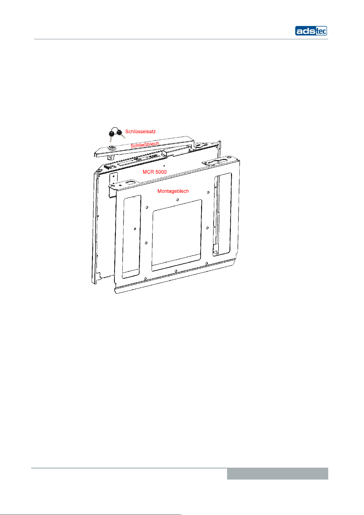
1.8 SCOPE OF DELIVERY
Please check that all of the following components are contained in the packaging:
•1 x MCR 5000
•1 x Installation bracket (pre-installed)
•1 x Locking plate (pre-installed)
•1 x Set of keys for locking-plate lock
The optional cable set might include the following individual cables:
1 x Rubber power lead
1 x Rubber power lead extension for monitor / display
1 x DVI cable
1 x Serial null-modem cable

Industrial PCs MCR5000
10 © ads-tec GmbH • Raiffeisenstr.14 • 70771 Leinfelden-Echterdingen
2OPERATING INSTRUCTIONS
This device contains electrical voltages and extremely sensitive components. The
manufacturer or a service partner authorised by the manufacturer should be consulted if
you plan to make any modifications. For this type of work, the device must be switched off
at the mains and the power lead must be disconnected. Suitable measures for avoiding
electrostatic discharge towards parts of the components when touching the equipment
must be taken. If the device is opened by an unauthorised person, hazards for the user
might arise and any warranty claim will cease.
GENERAL INSTRUCTIONS:
•All users must read this manual and have access to it at all times.
•Installation, commissioning and operation may only be carried out by trained and
qualified staff.
•The security instructions and the manual itself must be observed by all persons
who work with this device.
•At the location of use the valid guidelines and regulations for accident prevention
must be observed.
The accident prevention regulations according to the "BGV C1" Accident Prevention
& Insurance regulation must be observed, in particular.
•The manual contains the most important instructions on how to use this device in
a safe way.
•Appropriate storage, proper transport, installation and commissioning, as well as
careful operation are prerequisites for ensuring safe and proper operation of the
device.
Warning:
Any leads (e.g. power leads, interface cables) may only be connected if the device is
switched off in order to avoid damaging the device.
2.1 OPERATING LOCATION
The MCR 5000 model is designed for use with a monitor. You have to take care that the
environmental conditions specified in the "Technical data" chapter are met. Using the
device in non-specified environments, like e.g. onboard of ships, in areas that might
contain explosive gases or in extreme heights is prohibited.
Warning:
This device may only be switched on after the required ambient temperature is reached in
order to avoid condensate accumulation. The same applies if the device has previously
been exposed to extreme temperature variations.
To avoid overheating: The device must not be exposed to direct radiation by sunlight or
any other light or heat source.
2.2 DAMAGES DUE TO IMPROPER USE
Should the service system have evident signs of damages incurred e.g. due to wrong
operation or storage conditions or due to improper unit use, the unit must be
decommissioned or scrapped. Ensure that it is safe from accidental re-implementation.
Industrial PCs MCR5000
© ads-tec GmbH • Raiffeisenstr.14 • 70771 Leinfelden-Echterdingen 11
2.3 WARRANTY /REPAIRS
During the unit warranty period, any repairs thereto must strictly be conducted solely by
the manufacturer or by service personnel that has been duly authorised by the
manufacturer.
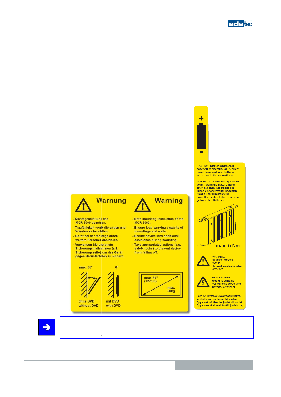
2.4 TREATMENT AND DISPOSAL OF LITHIUM BATTERIES
Warning:
There is an acute risk of explosion should the wrong type of battery be used.
Do not put lithium batteries into fire, do not solder on the cell body, do not recharge them,
open them, short-circuit them, do not reverse their polarity or heat them up over 100°C;
dispose of them properly and protect lithium batteries from direct sun light, humidity and
condensation.
Lithium batteries may only be replaced by the same type or by a type recommended by
the manufacturer.
The lithium battery must be disposed of according to the local legislation at the end of its
life cycle.
Note:
You'll find a detailed instruction on how to replace the lithium battery in the chapter
“Battery replacement".
2.5 SAFETY INSTRUCTIONS
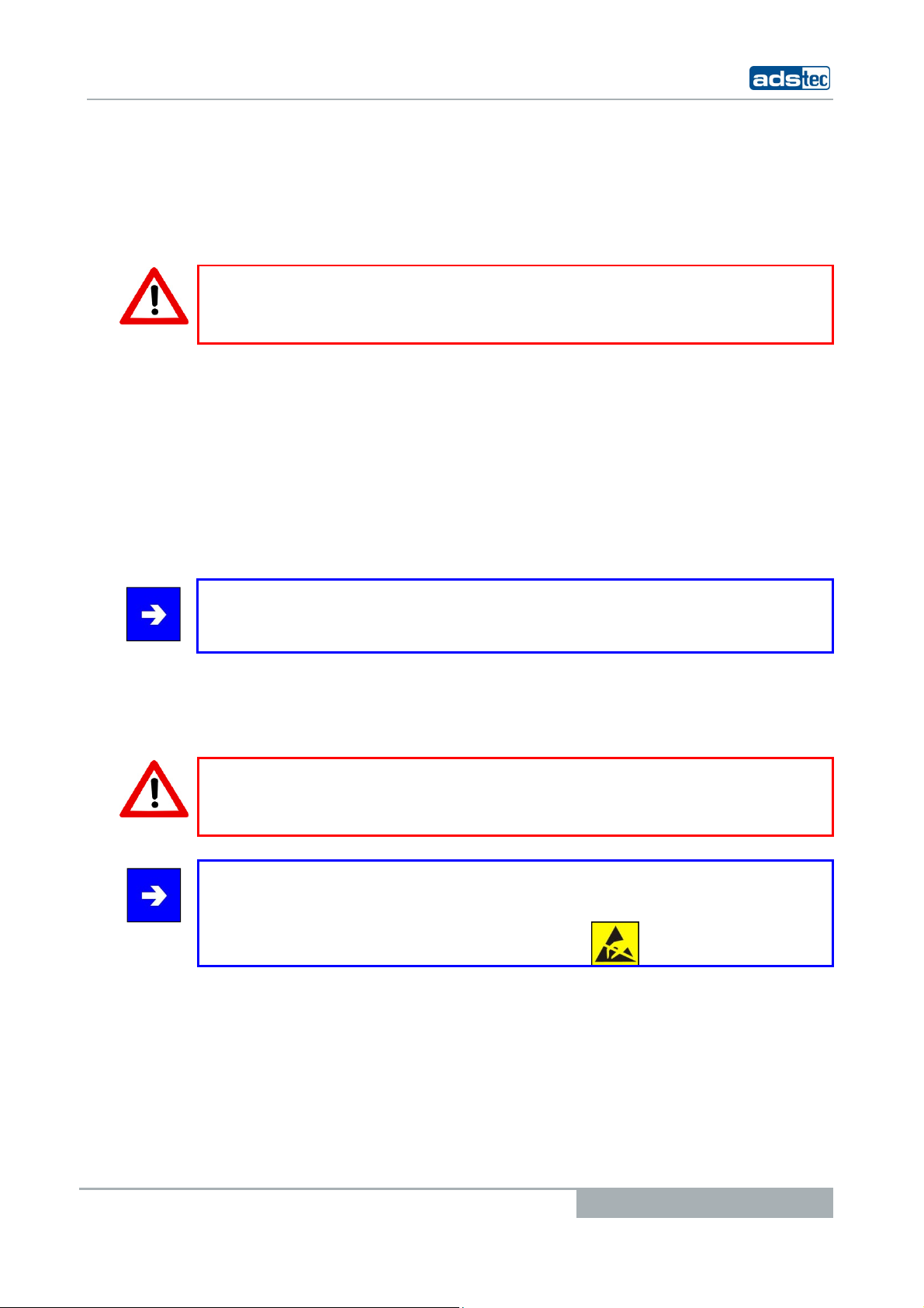
Warning:
All unit assembly operations must be strictly conducted only under safe, secure and zero-
potential conditions.
Special Note:
When handling parts and components susceptible to electrical discharge, please
accurately observe all the relevant safety provisions.
(DIN EN 61340-5-1 / DIN EN 61340-5-2 refers)
Industrial PCs MCR5000
12 © ads-tec GmbH • Raiffeisenstr.14 • 70771 Leinfelden-Echterdingen
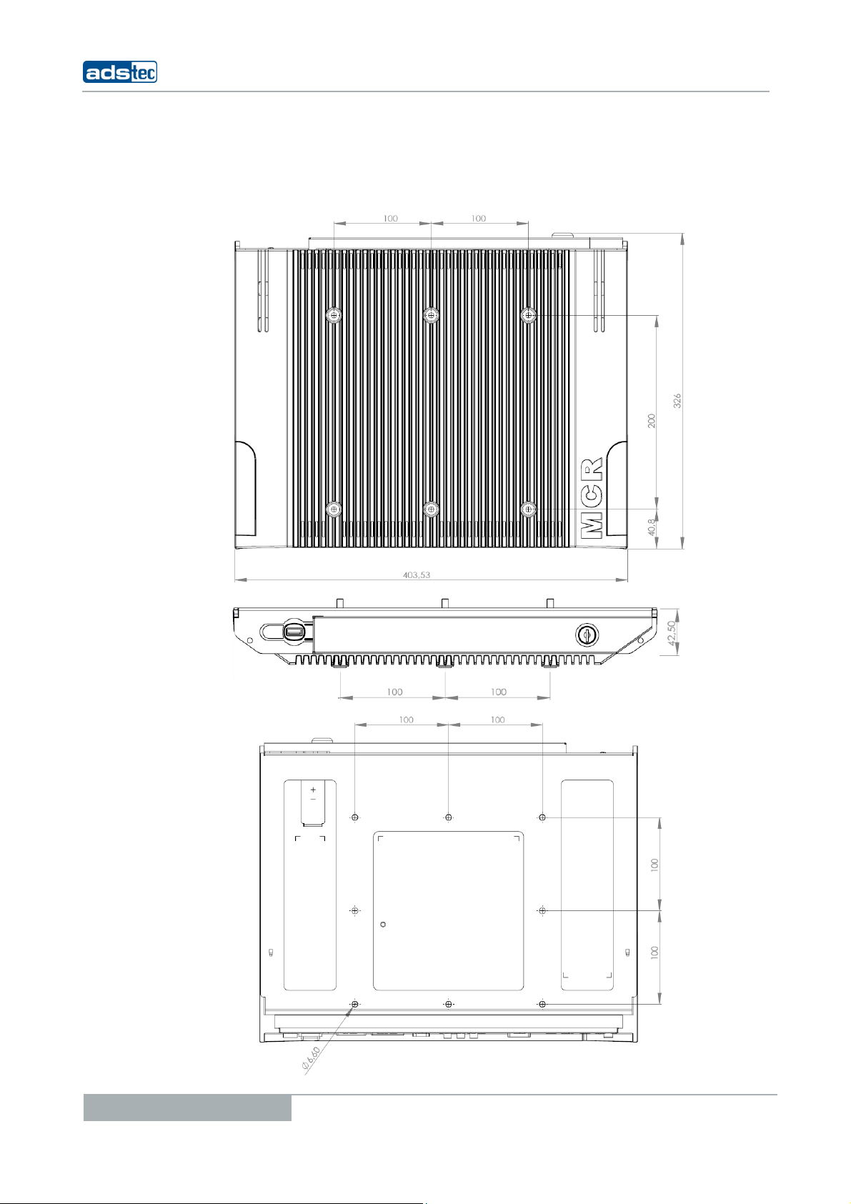
3ASSEMBLY
3.1 OVERALL DEVICE DIMENSIONS
Industrial PCs MCR5000
© ads-tec GmbH • Raiffeisenstr.14 • 70771 Leinfelden-
E
3.2 O
RDER OF INSTALLATI
O
The followin
g
must
•Check the
b
•Monitor is p
•Monitor wei
•Monitor siz
e
•Installation
(0° with DV
•Observe th
e
Note:
T
he maximum tor
q
installation. Ti
g
ht
en
Echterdingen
O
N
be checked before startin
g
the installation:
b
earin
g
capacity of the wall
ermitted for fixin
g
with M6 screws by VESA 100/
2
g
ht ≤50kg
e
≤50"
incline ≤30° from vertical line
D operation!)
e
monitor data sheet!
q
ue for fixin
g
the MCR 5000 installation screws
i
en
screws evenly.
13
2
00
i
s 5 Nm for wall-mount

Industrial PCs MCR5000
14 © ads-tec GmbH • Raiffeisenstr.14 • 70771 Leinfelden-Echterdingen
PREPARATION FOR FIXING
Warning:
The MCR 5000 device is designated for installation with a TFT or plasma display. Before
the MCR 5000 can be fixed to the display, the respective brackets or retainers for
protecting the MCR 5000 from falling must be in place. The fall protection measures must
correspond to the "BGV C1" regulations.
Respective retainers must be installed above the MCR 5000 device. As soon as the
retainers have been installed, the device should be secured with these brackets or
retainers (as it can be seen in the figure, for example).

Industrial PCs MCR5000
© ads-tec GmbH • Raiffeisenstr.14 • 70771 Leinfelden-Echterdingen 15
ATTACHING THE MCR 5000 IN THE PLACE OF INSTALLATION
The MCR 5000 device is installed including the pre-installed bracket at the place of
installation by using 6 x M6 screws and must be held in place by an additional person
during installation.
.
Attention:
a thread depth of at least 12 and at most 15 mm inside the MCR 5000 device must be
observed. Use all six screwing points.
EXAMPLE FOR INSTALLING THE MCR 5000 TO A WOODEN WALL FROM
18 MM PLYWOOD
Required installation materials (not included in the scope of delivery):
6 units of M6 x 35 Allen screw acc. to DIN 912
6 units of M6 washer for wooden constructions acc. to
DIN 440R
Note:
The screw length for each individual place of installation is determined in the following
way:
Wall thickness (18mm) + washer thickness (2 mm) + required penetration
depth (12 - 15mm) = screw length = 35 mm.
The 6 screws together with their washers will directly beneath the screw head be put
through holes drilled in the wall, screwed into the blind-rivet nuts in the MCR 5000 device,
and subsequently tightened with a torque of 5 Nm.
Industrial PCs MCR5000
16 © ads-tec GmbH • Raiffeisenstr.14 • 70771 Leinfelden-Echterdingen
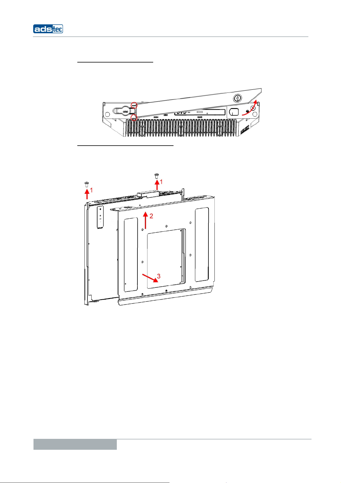
REMOVING THE LOCKING PLATE
The locking plate on the device must be removed in order to continue with the installation.
This is done by opening the lock and by removing the locking plate upwards.
REMOVING THE INSTALLATION BRACKET
For removing the installation bracket it is required to unhinge the previously attached
brackets or retainers. In this case, the MCR 5000 must be supported by another person.
The installation plate is unhinged after removing both safety screws from the MCR 5000.

Industrial PCs MCR5000
© ads-tec GmbH • Raiffeisenstr.14 • 70771 Leinfelden-Echterdingen 17
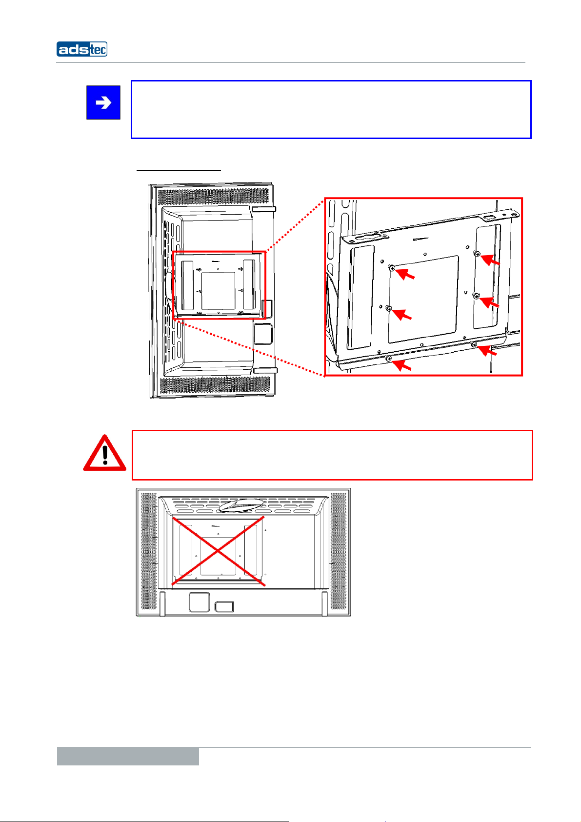
INSTALLING THE INSTALLATION BRACKET
The installation bracket including 6 x M6 screws must be screwed to the monitor according
to the instructions of the monitor manufacturer.
Horizontal installation:
Warning:
All six screws must be used for fixing the installation bracket.
Warning:
The permissible thread depth of the fixing screws inside the monitor case has to be
checked before installing the bracket on the monitor.
Industrial PCs MCR5000
18 © ads-tec GmbH • Raiffeisenstr.14 • 70771 Leinfelden-Echterdingen
Note:
Vertical installation is possible depending on the purpose of use and the installation
conditions at the display. For this purpose the monitor has to be installed in a tilted
position according to the manufacturer instructions.
Vertical installation:
Warning:
The installation adapter must always be attached in the centre with both installation
methods. Verify if vertical operation is permitted for your display unit.

Industrial PCs MCR5000
© ads-tec GmbH • Raiffeisenstr.14 • 70771 Leinfelden-Echterdingen 19
MONITOR INSTALLATION AT THE MCR 5000
Warning:
The installation procedure described below must be carried out by at least 3 persons, due
to the weight of the equipment.
Fix the monitor to the MCR 5000 device by using the pre-installed installation bracket.
Note:
The figure shows the installation bracket from the point of view of the monitor. Please
take care that the monitor plate is properly pushed into the guides provided on the MCR
5000 case when attaching the monitor.

Industrial PCs MCR5000
20 © ads-tec GmbH • Raiffeisenstr.14 • 70771 Leinfelden-Echterdingen
Subsequently, the monitor must be pushed beyond the retainer lobes. Make sure that the
installation bracket is flush with the MCR 5000 unit after installation.
Other manuals for MCR5000
1
Table of contents
Other ADS-tec Desktop manuals


Popular Desktop manuals by other brands


Advantech
Advantech ARK-2150 user manual

HP
HP Xw4300 - Workstation - 2 GB RAM installation guide

HP
HP Pavilion Media Center m8000 - Desktop PC Setup poster

Wincor Nixdorf
Wincor Nixdorf BEETLE /M-II technical information

Sony
Sony VAIO Digital Studio PCV-RX790G specification

Kettler
Kettler SM 3135-23 manual


