2 Section 61246043L3-5, Issue 1 61246043L3-5A
C A U T I O N
!
SUBJECT TO ELECTROSTATIC DAMAGE
OR DECREASE IN RELIABILITY.
HANDLING PRECAUTIONS REQUIRED.
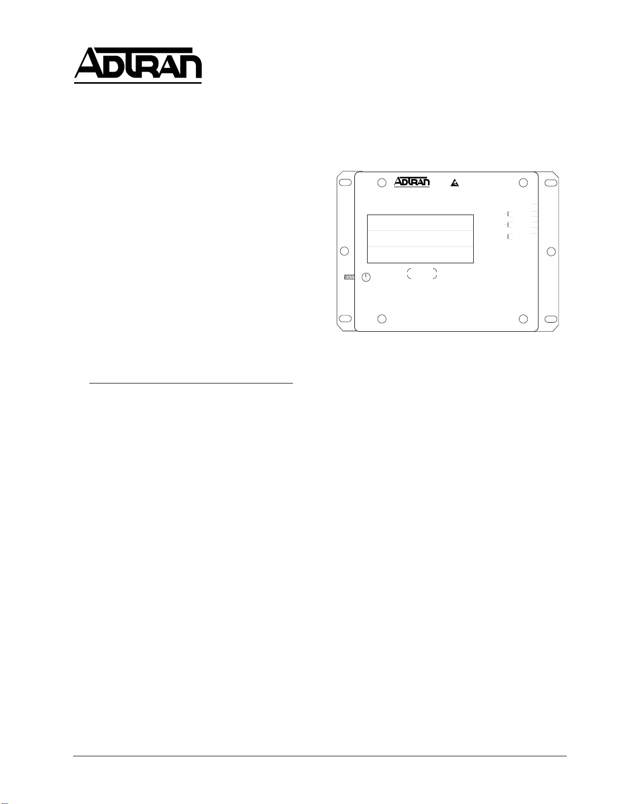
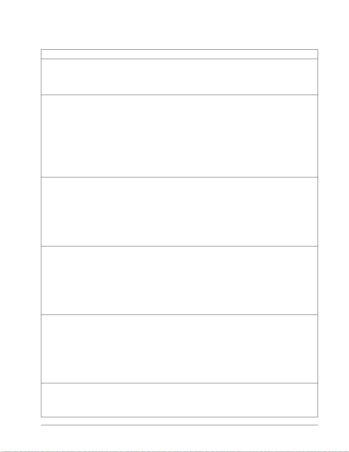
3. FACEPLATE FEATURES
The ADTRAN REG faceplate has four tricolored
LEDs, a power LED, and a test LED indicating
different states of the HDSL circuit. Table 1
explains the meaning of the different LED
indications.
The REG-R LEDs indicate the status of the HDSL
transceivers that are connected to the LTU. The
REG-C LEDs indicate the status of the HDSL
transceivers that are conencted to the NTU.
4. MAINTENANCE
The ADTRAN E1 HDSL REG requires no routine
maintenance. Performance monitoring, diagnostics,
and loopbacks are available from the craft interface
at the LTU and NTU.
When testing indicates a faulty Encapsulated REG,
replace it.
ADTRAN does not recommend field repair of the
Encapsulated REG. Repair services may be
obtained by returning the defective unit to the
ADTRAN Repair Department.
5. DEPLOYMENT GUIDELINES
The ADTRAN HDSL system is designed to provide
E1 services over loops designed to comply with
ETSI guidelines. Deployment guidelines are given
below.
1. All loops are non-loaded only.
2. For loops with 0.5 mm cable, the maximum
loop length including bridged tap lengths is
4.75 km per loop.
3. Any single bridged tap is limited to 500 m.
4. Maximum number of bridge taps per loop is 2.
NOTE
These approximations are to be used as
guidelines only and may vary slightly on
different loops. Adhering to the guidelines
should produce performance in excess of 10-7
BER.
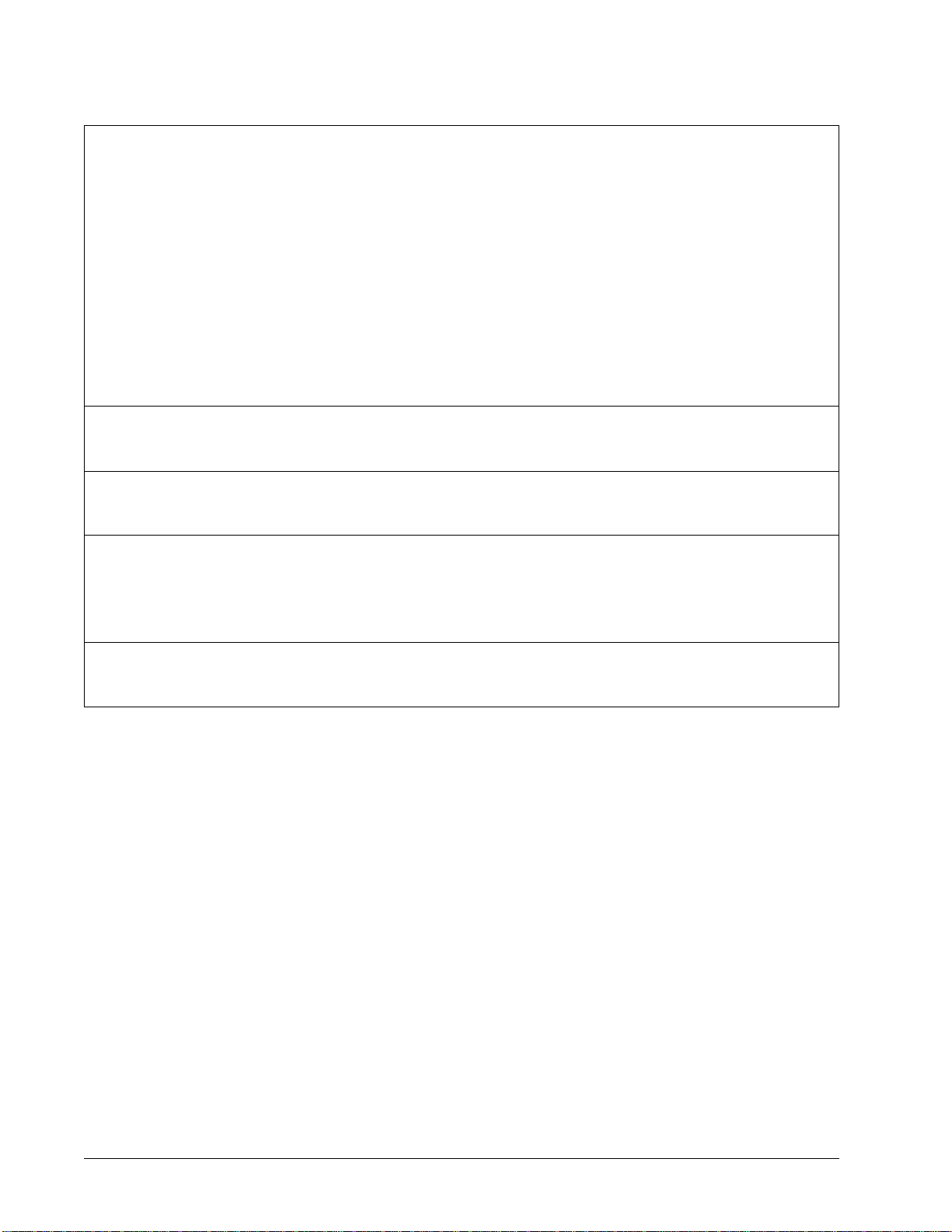
6. SPECIFICATIONS
Table 2 lists the REG specifications.
Revision History
This is the initial release of this document. Future
revisions to this document will be explained in this
subsection.
2. INSTALLATION
The REG can be mounted using bolts, tie wraps, or
other suitable anchoring means.
Remove the E1 HDSL REG from the overpack and
visually ensure that damage has not occurred during
shipping or handling. If damage has occurred, file a
claim immediately with your distributor, then
contact ADTRAN customer service.
Select a suitable site or pole along the main cable
where the loop loss does not exceed 27 dB at
150 kHz as measured from the LTU site to the REG
site. The loop loss from the REG site to the NTU
site should also not exceed 27 dB at 150 kHz unless
a bit error rate BER) measurement is performed to
ensure a maximum BER of less than 1 x 10⁻⁷.
CAUTION
Be aware of span powering when connecting
the HDSL loops.
HDSL Pair Connections
• Connect the Green/White twisted pair of wires
to the Exchange pair Loop 1.
• Connect the Orange/White twisted pair of wires
to the Exchange pair Loop 2.
• Connect the Blue/Red twisted pair of wires to
the Customer pair Loop 1.
• Connect the Blue/White twisted pair of wires to
the Customer pair Loop 2.
• Connect the 10 AWG ground wire on the
Encapsulated REG to a suitable Earth Ground
connection.
• The Brown/White and Slate/White pairs are
unused.
Compliance
This product complies with EN 300, 386-2 and IEC
950. It is intended to be installed in a Restricted
Access location only.