manuals.online logo
Brands
  1. Home
  2. •
  3. Brands
  4. •
  5. Tektronix
  6. •
  7. Portable Generator
  8. •
  9. Tektronix TSG200 User manual

Tektronix TSG200 User manual

The test & measurement
equipment you need at
the price you want.
Alltest carries the world’s largest selection of
used/refurbished benchtop test & measurement
equipment at 50% the price of new.
O
Our equipment is guaranteed working, warrantied, and
available with certified calibration from our in-house staff
of technicians and engineers.
• 10+ full time technicians with over 150 years of
specialization
• 90 day warranty & 5 day right of return on all
equipment
•
• 1-3 year warranties for new and
premium-refurbished equipment
• Every unit tested to OEM specifications
• Satisfaction guaranteed
You have plans, we will help you achieve them.
Any project. Any budget.
Get a quote today!
CCall (732) 919-3339 or email sales@alltest.net.
t
Alltest Instruments, Inc.
500 Central Ave.
Farmingdale, NJ 07727
P: (732) 919-3339
F: (732) 919-3332
alltest.net
s
sales@alltest.net
Instruction Manual
TSG200
NTSC Signal Generator
071-0760-00
Warning
The servicing instructions are for use by qualified
personnel only. To avoid personal injury, do not
perform any servicing unless you are qualified to
do so. Refer to all safety summaries prior to
performing service.
www.tektronix.com
Copyright ©Tektronix, Inc. All rights reserved.
Tektronix products are covered by U.S. and foreign patents, issued and pending. Information in this publication supercedes
that in all previously published material. Specifications and price change privileges reserved.
Tektronix, Inc., P.O. Box 500, Beaverton, OR 97077
TEKTRONIX and TEK are registered trademarks of Tektronix, Inc.
WARRANTY
Tektronix warrants that the products that it manufactures and sells will be free from defects in materials and
workmanship for a period of one (1) year from the date of shipment. If a product proves defective during this
warranty period, Tektronix, at its option, either will repair the defective product without charge for parts and labor,
or will provide a replacement in exchange for the defective product.
In order to obtain service under this warranty, Customer must notify Tektronix of the defect before the expiration
of the warranty period and make suitable arrangements for the performance of service. Customer shall be
responsible for packaging and shipping the defective product to the service center designated by Tektronix, with
shipping charges prepaid. Tektronix shall pay for the return of the product to Customer if the shipment is to a
location within the country in which the Tektronix service center is located. Customer shall be responsible for
paying all shipping charges, duties, taxes, and any other charges for products returned to any other locations.
This warranty shall not apply to any defect, failure or damage caused by improper use or improper or inadequate
maintenance and care. Tektronix shall not be obligated to furnish service under this warranty a) to repair damage
resulting from attempts by personnel other than Tektronix representatives to install, repair or service the product;
b) to repair damage resulting from improper use or connection to incompatible equipment; c) to repair any
damage or malfunction caused by the use of non-Tektronix supplies; or d) to service a product that has been
modified or integrated with other products when the effect of such modification or integration increases the time
or difficulty of servicing the product.
THIS WARRANTY IS GIVEN BY TEKTRONIX IN LIEU OF ANY OTHER WARRANTIES, EXPRESS
OR IMPLIED. TEKTRONIX AND ITS VENDORS DISCLAIM ANY IMPLIED WARRANTIES OF
MERCHANTABILITY OR FITNESS FOR A PARTICULAR PURPOSE. TEKTRONIX’
RESPONSIBILITY TO REPAIR OR REPLACE DEFECTIVE PRODUCTS IS THE SOLE AND
EXCLUSIVE REMEDY PROVIDED TO THE CUSTOMER FOR BREACH OF THIS WARRANTY.
TEKTRONIX AND ITS VENDORS WILL NOT BE LIABLE FOR ANY INDIRECT, SPECIAL,
INCIDENTAL, OR CONSEQUENTIAL DAMAGES IRRESPECTIVE OF WHETHER TEKTRONIX OR
THE VENDOR HAS ADVANCE NOTICE OF THE POSSIBILITY OF SUCH DAMAGES.
General Safety Summary
Review the following safety precautions to avoid injury and prevent damage to
this product or any products connected to it. To avoid potential hazards, use this
product only as specified.
Use Proper Power Cord. Use only the power cord specified for this product and
certified for the country of use.
Use Proper Voltage Setting. Before applying power, ensure that the line selector is
in the proper position for the power source being used.
Ground the Product. This product is grounded through the grounding conductor
of the power cord. To avoid electric shock, the grounding conductor must be
connected to earth ground. Before making connections to the input or output
terminals of the product, ensure that the product is properly grounded.
Observe All Terminal Ratings. To avoid fire or shock hazard, observe all ratings
and markings on the product. Consult the product manual for further ratings
information before making connections to the product.
Do not apply a potential to any terminal, including the common terminal, that
exceeds the maximum rating of that terminal.
Use Proper AC Adapter. Use only the AC adapter specified for this product.
Do Not Operate Without Covers. Do not operate this product with covers or panels
removed.
Use Proper Fuse. Use only the fuse type and rating specified for this product.
Avoid Exposed Circuitry. Do not touch exposed connections and components
when power is present.
Wear Eye Protection. Wear eye protection if exposure to high-intensity rays or
laser radiation exists.
Do Not Operate With SuspectedFailures. If you suspect there is damage to this
product, have it inspected by qualified service personnel.
Do Not Operate in an Explosive Atmosphere.
Do Not Service Alone. Do not perform internal service or adjustments of this
product unless another person capable of rendering first aid and resuscitation is
present.
To Avoid Fire or
Personal Injury
General Safety Summary TSG 200
Terms in this Manual. These terms may appear in this manual:
WARNING. Warning statements identify conditions or practices that could result
in injury or loss of life.
CAUTION. Caution statements identify conditions or practices that could result in
damage to this product or other property.
Terms on the Product. These terms may appear on the product:
DANGER indicates an injury hazard immediately accessible as you read the
marking.
WARNING indicates an injury hazard not immediately accessible as you read the
marking.
CAUTION indicates a hazard to property including the product.
Symbols on the Product. The following symbols may appear on the product:
CAUTION
Refer to Manual WARNING
High Voltage ProtectiveGround
(Earth) Terminal
Symbols and Terms
Table of Contents
i
Table of Contents
SECTION 1
INTRODUCTION
SECTION 2
CONTROLS, INDICATORS, & CONNECTORS
Front Panel Controls 2-1. . . . . . . . . . . . . . . . . . . . . . . . . . . . . . . . . . . . . . . . . . . . . . . . . . . . . . . . . . . . . . . . . . .
SIGNAL SELECT 2-1. . . . . . . . . . . . . . . . . . . . . . . . . . . . . . . . . . . . . . . . . . . . . . . . . . . . . . . . . . . . . . . .

FUNCTIONS ENABLE 2-1. . . . . . . . . . . . . . . . . . . . . . . . . . . . . . . . . . . . . . . . . . . . . . . . . . . . . . . . . . .



TAPE LEADER
(Tape Leader Countdown) 2-2. . . . . . . . . . . . . . . . . . . . . . . . . . . . . . . . . . . . . . . . . . . . . . .

AUDIO CLICK 2-2. . . . . . . . . . . . . . . . . . . . . . . . . . . . . . . . . . . . . . . . . . . . . . . . . . . . . . . . . . . . .
CHAR ID
(Display the Character ID on Active Video) 2-2. . . . . . . . . . . . . . . . . . . . . . . . . . . . . . . . .
ID CYCLE 2-2. . . . . . . . . . . . . . . . . . . . . . . . . . . . . . . . . . . . . . . . . . . . . . . . . . . . . . . . . . . . . . . .
VBI CHAR ID
(Vertical Blanking Interval Character ID) 2-3. . . . . . . . . . . . . . . . . . . . . . . . . . . . . . . . . . .
SID
(Vertical Interval Source Identification Code 2-3. . . . . . . . . . . . . . . . . . . . . . . . . . . . . . . .
ID SETUP & Direction Arrows 2-3. . . . . . . . . . . . . . . . . . . . . . . . . . . . . . . . . . . . . . . . . . . . . . . . . . . . .
ID TEXT 2-3. . . . . . . . . . . . . . . . . . . . . . . . . . . . . . . . . . . . . . . . . . . . . . . . . . . . . . . . . . . . . . . . . .
ID DISPLAY 2-4. . . . . . . . . . . . . . . . . . . . . . . . . . . . . . . . . . . . . . . . . . . . . . . . . . . . . . . . . . . . . . .
ID STORE/RECALL 2-4. . . . . . . . . . . . . . . . . . . . . . . . . . . . . . . . . . . . . . . . . . . . . . . . . . . . . . . .
ID CYCLE 2-4. . . . . . . . . . . . . . . . . . . . . . . . . . . . . . . . . . . . . . . . . . . . . . . . . . . . . . . . . . . . . . . .
Using the ID SETUP Commands 2-4. . . . . . . . . . . . . . . . . . . . . . . . . . . . . . . . . . . . . . . . . . . . . . . . . .
General Information 2-4. . . . . . . . . . . . . . . . . . . . . . . . . . . . . . . . . . . . . . . . . . . . . . . . . . . . . . . .
Setting the ID TEXT 2-5. . . . . . . . . . . . . . . . . . . . . . . . . . . . . . . . . . . . . . . . . . . . . . . . . . . . . . . .
Setting the ID DISPLAY 2-6. . . . . . . . . . . . . . . . . . . . . . . . . . . . . . . . . . . . . . . . . . . . . . . . . . . .
Using the ID STORE/RECALL 2-7. . . . . . . . . . . . . . . . . . . . . . . . . . . . . . . . . . . . . . . . . . . . . . .
Setting the ID CYCLE 2-9. . . . . . . . . . . . . . . . . . . . . . . . . . . . . . . . . . . . . . . . . . . . . . . . . . . . . .
FRONT PANEL LOCKOUT 2-10. . . . . . . . . . . . . . . . . . . . . . . . . . . . . . . . . . . . . . . . . . . . . . . . . . . . . . .
REAR PANEL CONNECTORS 2-11. . . . . . . . . . . . . . . . . . . . . . . . . . . . . . . . . . . . . . . . . . . . . . . . . . . . . . . . . .
Using the REMOTE 2-13. . . . . . . . . . . . . . . . . . . . . . . . . . . . . . . . . . . . . . . . . . . . . . . . . . . . . . . . . . . . . .
Pin 1 – Tape Leader 2-13. . . . . . . . . . . . . . . . . . . . . . . . . . . . . . . . . . . . . . . . . . . . . . . . . . . . . . . .
Pin 2 – Signal Selection 2-13. . . . . . . . . . . . . . . . . . . . . . . . . . . . . . . . . . . . . . . . . . . . . . . . . . . .
Pin 3 – Function Enable/Disable 2-14. . . . . . . . . . . . . . . . . . . . . . . . . . . . . . . . . . . . . . . . . . . . .
Pin 4 – ID Recall 2-14. . . . . . . . . . . . . . . . . . . . . . . . . . . . . . . . . . . . . . . . . . . . . . . . . . . . . . . . . . .
Pin 5 – Front Panel Lockout 2-14. . . . . . . . . . . . . . . . . . . . . . . . . . . . . . . . . . . . . . . . . . . . . . . . .
SECTION 3
SIGNAL GENERATOR SPECIFICATIONS
Reference Documentation 3-1. . . . . . . . . . . . . . . . . . . . . . . . . . . . . . . . . . . . . . . . . . . . . . . . . . . . . . . . . . . . . .
Performance Conditions 3-1. . . . . . . . . . . . . . . . . . . . . . . . . . . . . . . . . . . . . . . . . . . . . . . . . . . . . . . . . . . . . . . .
Safety Standards 3-1. . . . . . . . . . . . . . . . . . . . . . . . . . . . . . . . . . . . . . . . . . . . . . . . . . . . . . . . . . . . . . . . . . . . . .
TEST SIGNALS 3-11. . . . . . . . . . . . . . . . . . . . . . . . . . . . . . . . . . . . . . . . . . . . . . . . . . . . . . . . . . . . . . . . . . . . . . .
Table of Contents
ii
SECTION 4
PERFORMANCE CHECKS & ADJUSTMENT PROCEDURES
List of Required Test Equipment 4-1. . . . . . . . . . . . . . . . . . . . . . . . . . . . . . . . . . . . . . . . . . . . . . . . . . .
PERFORMANCE CHECK PROCEDURES 4-2. . . . . . . . . . . . . . . . . . . . . . . . . . . . . . . . . . . . . . . . . . . . . . .
Oscillator Frequency 4-2. . . . . . . . . . . . . . . . . . . . . . . . . . . . . . . . . . . . . . . . . . . . . . . . . . . . . . . . . . . . .
Test Signal 4-2. . . . . . . . . . . . . . . . . . . . . . . . . . . . . . . . . . . . . . . . . . . . . . . . . . . . . . . . . . . . . . . . . . . . .
Black Outputs 4-2. . . . . . . . . . . . . . . . . . . . . . . . . . . . . . . . . . . . . . . . . . . . . . . . . . . . . . . . . . . . . . . . . . .
Audio Output 4-2. . . . . . . . . . . . . . . . . . . . . . . . . . . . . . . . . . . . . . . . . . . . . . . . . . . . . . . . . . . . . . . . . . . .
PERFORMANCE CHECK PROCEDURES 4-3. . . . . . . . . . . . . . . . . . . . . . . . . . . . . . . . . . . . . . . . . . . . . . .
Oscillator Frequency 4-3. . . . . . . . . . . . . . . . . . . . . . . . . . . . . . . . . . . . . . . . . . . . . . . . . . . . . . . . . . . . .
Test Signal 4-4. . . . . . . . . . . . . . . . . . . . . . . . . . . . . . . . . . . . . . . . . . . . . . . . . . . . . . . . . . . . . . . . . . . . .
Black Outputs 4-7. . . . . . . . . . . . . . . . . . . . . . . . . . . . . . . . . . . . . . . . . . . . . . . . . . . . . . . . . . . . . . . . . . .
Audio Output 4-7. . . . . . . . . . . . . . . . . . . . . . . . . . . . . . . . . . . . . . . . . . . . . . . . . . . . . . . . . . . . . . . . . . . .
ADJUSTMENT PROCEDURE CHECKLIST 4-9. . . . . . . . . . . . . . . . . . . . . . . . . . . . . . . . . . . . . . . . . . . . . .
ADJUSTMENT PROCEDURES 4-10. . . . . . . . . . . . . . . . . . . . . . . . . . . . . . . . . . . . . . . . . . . . . . . . . . . . . . . . .
SECTION 5
INSTALLATION
Selecting the Power Supply Mains Voltage 5-1. . . . . . . . . . . . . . . . . . . . . . . . . . . . . . . . . . . . . . . . . .
Selecting the Audio Tone Frequency 5-1. . . . . . . . . . . . . . . . . . . . . . . . . . . . . . . . . . . . . . . . . . . . . . .
Adjusting the Audio Click Frequency 5-2. . . . . . . . . . . . . . . . . . . . . . . . . . . . . . . . . . . . . . . . . . . . . . .
Configuring NTSC/BLACK Output 5-2. . . . . . . . . . . . . . . . . . . . . . . . . . . . . . . . . . . . . . . . . . . . . . . . .
Setting the SID 5-2. . . . . . . . . . . . . . . . . . . . . . . . . . . . . . . . . . . . . . . . . . . . . . . . . . . . . . . . . . . . . . . . . .
Initializing the Non–Volatile Memory 5-3. . . . . . . . . . . . . . . . . . . . . . . . . . . . . . . . . . . . . . . . . . . . . . . .
Customizing the Settings 5-4. . . . . . . . . . . . . . . . . . . . . . . . . . . . . . . . . . . . . . . . . . . . . . . . . . . . . . . . .
List of Jumpers and Switches 5-5. . . . . . . . . . . . . . . . . . . . . . . . . . . . . . . . . . . . . . . . . . . . . . . . . . . . . . . . . . .
SECTION 6
OPTIONS
OPTION – 1J –– (0% Setup) 6-1. . . . . . . . . . . . . . . . . . . . . . . . . . . . . . . . . . . . . . . . . . . . . . . . . . . . . . . . . . . .
Changes to: Section 3 – Specifications 6-1. . . . . . . . . . . . . . . . . . . . . . . . . . . . . . . . . . . . . . . . . . . . .
Changes to: Section 5 – Performance Check and Adjustment Procedure 6-4. . . . . . . . . . . . . . .
SECTION 7
BLOCK DIAGRAM
SECTION 8
REPLACEABLE ELECTRICAL PARTS
SECTION 9
DIAGRAMS/CIRCUIT BAORD ILLUSTRATIONS
SECTION 10
REPLACEABLE MECHANICAL PARTS
Table of Contents
iii
List of Figures
SECTION 1
INTRODUCTION
Fig. 1-1. Front Panel of the TSG 200 1-1. . . . . . . . . . . . . . . . . . . . . . . . . . . . . . . . . . . . . . . . . . . . . . .
Fig. 1-2. Rear Panel of the TSG 200 1-1. . . . . . . . . . . . . . . . . . . . . . . . . . . . . . . . . . . . . . . . . . . . . . .
SECTION 2
CONTROLS, INDICATORS, & CONNECTORS
Fig. 2-1. The SIGNAL SELECT control block 2-1. . . . . . . . . . . . . . . . . . . . . . . . . . . . . . . . . . . . . . . .
Fig. 2-2. The FUNCTIONS ENABLE control block 2-1. . . . . . . . . . . . . . . . . . . . . . . . . . . . . . . . . . .
Fig. 2-3. Location of the Vertical Interval ID
(Monitor set to display the Vertical Interval) 2-3. . . . . . . . . . . . . . . . . . . . . . . . . . . . . . . . . . . . . .
Fig. 2-4. ID SETUP and direction arrows 2-3. . . . . . . . . . . . . . . . . . . . . . . . . . . . . . . . . . . . . . . . . . .
Fig. 2-5. Legal range for Character ID diaplay. The Safe Title area is defined by the
inner lines while the Safe Action area is marked by the outer set of lines. 2-4. . . . . . . . . . . .
Fig. 2-6. How to change the character in the CHARACTER ID 2-5. . . . . . . . . . . . . . . . . . . . . . . . .
Fig. 2-7. How to select a character 2-5. . . . . . . . . . . . . . . . . . . . . . . . . . . . . . . . . . . . . . . . . . . . . . . . .
Fig. 2-8. Legal range for Character ID diaplay. The Safe Title area is defined by the
inner lines while the Safe Action area is marked by the outer set of lines.
It is recommended that the ID be in the Safe Title area 2-6. . . . . . . . . . . . . . . . . . . . . . . . . . . .
Fig. 2-9. Monitor display when in ID STORE/RECALL 2-7. . . . . . . . . . . . . . . . . . . . . . . . . . . . . . . .
Fig. 2-10. The monitor display to set the POWER UP DEFAULT 2-8. . . . . . . . . . . . . . . . . . . . . . .
Fig. 2-11. Monitor display when in ID CYCLE Setup 2-9. . . . . . . . . . . . . . . . . . . . . . . . . . . . . . . . . .
Fig. 2-12. Location of the FRONT PANEL LOCKOUT indicator 2-10. . . . . . . . . . . . . . . . . . . . . . . .
Fig. 2-13. Rear panel of the TSG 200 2-11. . . . . . . . . . . . . . . . . . . . . . . . . . . . . . . . . . . . . . . . . . . . . .
Fig. 2-14. DC IN connector values 2-11. . . . . . . . . . . . . . . . . . . . . . . . . . . . . . . . . . . . . . . . . . . . . . . . .
Fig. 2-15. The REMOTE connector pinout (Looking into the TSG 200) 2-12. . . . . . . . . . . . . . . . . .
Fig. 2-16. FRONT PANEL LOCKOUT indicator 2-14. . . . . . . . . . . . . . . . . . . . . . . . . . . . . . . . . . . . . .
SECTION 3
SIGNAL GENERATOR SPECIFICATIONS
Fig. 3-1. Physical deminsions of the TSG 200 3-8. . . . . . . . . . . . . . . . . . . . . . . . . . . . . . . . . . . . . . .
Fig. 3-2. SMPTE Color Bars 3-11. . . . . . . . . . . . . . . . . . . . . . . . . . . . . . . . . . . . . . . . . . . . . . . . . . . . . .
Fig. 3-3. SMPTE Reverse Blue Bars 3-11. . . . . . . . . . . . . . . . . . . . . . . . . . . . . . . . . . . . . . . . . . . . . . .
Fig. 3-4. SMPTE IYQB 3-12. . . . . . . . . . . . . . . . . . . . . . . . . . . . . . . . . . . . . . . . . . . . . . . . . . . . . . . . . . .
Fig. 3-5. 5–Step (Gray Scale) 3-12. . . . . . . . . . . . . . . . . . . . . . . . . . . . . . . . . . . . . . . . . . . . . . . . . . . . .
Fig. 3-6. Convergence (vertical) 3-13. . . . . . . . . . . . . . . . . . . . . . . . . . . . . . . . . . . . . . . . . . . . . . . . . . .
Fig. 3-7. Convergence (horizontal) 3-13. . . . . . . . . . . . . . . . . . . . . . . . . . . . . . . . . . . . . . . . . . . . . . . . .
Fig. 3-8. NTC 7 Composite 3-14. . . . . . . . . . . . . . . . . . . . . . . . . . . . . . . . . . . . . . . . . . . . . . . . . . . . . . .
Fig. 3-9. Multiburst 3-14. . . . . . . . . . . . . . . . . . . . . . . . . . . . . . . . . . . . . . . . . . . . . . . . . . . . . . . . . . . . . . .
Fig. 3-10 Safe Area for lines: 33, 45, 238, & 250 3-15. . . . . . . . . . . . . . . . . . . . . . . . . . . . . . . . . . . . .
Fig. 3-11. Safe Area for lines: 69-132 & 149-214 3-15. . . . . . . . . . . . . . . . . . . . . . . . . . . . . . . . . . . . .
Fig. 3-12. Safe Area for lines: 133-140 & 142-148 3-16. . . . . . . . . . . . . . . . . . . . . . . . . . . . . . . . . . .
Fig. 3-13. Safe Area for line 141 3-16. . . . . . . . . . . . . . . . . . . . . . . . . . . . . . . . . . . . . . . . . . . . . . . . . . .
Fig. 3-14. Safe Area for all other lines 3-17. . . . . . . . . . . . . . . . . . . . . . . . . . . . . . . . . . . . . . . . . . . . . .
Fig. 3-15. Video monitor display of Safe Area signal 3-17. . . . . . . . . . . . . . . . . . . . . . . . . . . . . . . . . .
Fig. 3–16. Black Burst 3-18. . . . . . . . . . . . . . . . . . . . . . . . . . . . . . . . . . . . . . . . . . . . . . . . . . . . . . . . . . . .
Table of Contents
iv
SECTION 4
PERFORMANCE CHECKS & ADJUSTMENT PROCEDURES
Fig. 4-1. Setup to check the crystal frequency 4-3. . . . . . . . . . . . . . . . . . . . . . . . . . . . . . . . . . . . . . .
Fig. 4-2. Basic setup for the Performance Checks 4-4. . . . . . . . . . . . . . . . . . . . . . . . . . . . . . . . . . .
Fig. 4-3. Setup to measure the total harmonic distortion 4-7. . . . . . . . . . . . . . . . . . . . . . . . . . . . . .
Fig. 4-4. Setup to adjust the oscillator frequency 4-10. . . . . . . . . . . . . . . . . . . . . . . . . . . . . . . . . . . . .
Fig. 4-5. Audio amplitude calibration setup 4-10. . . . . . . . . . . . . . . . . . . . . . . . . . . . . . . . . . . . . . . . . .
Fig. 4-6. Audio ID click frequency adjustment setup 4-11. . . . . . . . . . . . . . . . . . . . . . . . . . . . . . . . . .
Fig. 4-7. Basic setup for the calibration procedures 4-11. . . . . . . . . . . . . . . . . . . . . . . . . . . . . . . . . .
Fig. 4-8. New functions of the Signal Select buttons in the Diagnostic
Test Signal mode 4-12. . . . . . . . . . . . . . . . . . . . . . . . . . . . . . . . . . . . . . . . . . . . . . . . . . . . . . . . . . . . .
SECTION 5
INSTALLATION
Fig. 5-1. Audio ID click frequency adjustment setup 5-2. . . . . . . . . . . . . . . . . . . . . . . . . . . . . . . . . .
Fig. 5-2. Monitor display to set ”FACTORY SETTING” 5-3. . . . . . . . . . . . . . . . . . . . . . . . . . . . . . . .
Fig. 5-3. Monitor display to customize th eTSG 200 5-4. . . . . . . . . . . . . . . . . . . . . . . . . . . . . . . . . .
SECTION 6
OPTIONS
Fig. 6-1. SMPTE Color Bars 6-2. . . . . . . . . . . . . . . . . . . . . . . . . . . . . . . . . . . . . . . . . . . . . . . . . . . . . .
Fig. 6-2. SMPTE Reverse Blue Bars 6-2. . . . . . . . . . . . . . . . . . . . . . . . . . . . . . . . . . . . . . . . . . . . . . .
Fig. 6-3. SMPTE IYQB 6-3. . . . . . . . . . . . . . . . . . . . . . . . . . . . . . . . . . . . . . . . . . . . . . . . . . . . . . . . . . .
Fig. 6-4. Black Burst 6-3. . . . . . . . . . . . . . . . . . . . . . . . . . . . . . . . . . . . . . . . . . . . . . . . . . . . . . . . . . . . .
Table of Contents
v
List of Tables
SECTION 2
CONTROLS, INDICATORS, & CONNECTORS
Table 2-1. Binary Code for Signal Selection 2-13. . . . . . . . . . . . . . . . . . . . . . . . . . . . . . . . . . . . . . . . .
Table 2-2. Binary Code for Function Enable/Disable 2-14. . . . . . . . . . . . . . . . . . . . . . . . . . . . . . . . . .
Table 2-3. Binary Code for Character ID Recall 2-14. . . . . . . . . . . . . . . . . . . . . . . . . . . . . . . . . . . . . .
SECTION 3
SIGNAL GENERATOR SPECIFICATIONS
Table 3-1. General Test Signal Characteristics 3-2. . . . . . . . . . . . . . . . . . . . . . . . . . . . . . . . . . . . . . .
Table 3-2. Test Signals 3-4. . . . . . . . . . . . . . . . . . . . . . . . . . . . . . . . . . . . . . . . . . . . . . . . . . . . . . . . . . .
Table 3-3. Test Signal Generator – Black Burst Output 3-5. . . . . . . . . . . . . . . . . . . . . . . . . . . . . . . .
Table 3-4. Character Identification 3-6. . . . . . . . . . . . . . . . . . . . . . . . . . . . . . . . . . . . . . . . . . . . . . . . .
Table 3-5. Audio Tone Characteristics 3-6. . . . . . . . . . . . . . . . . . . . . . . . . . . . . . . . . . . . . . . . . . . . . .
Table 3-6. Power Supply Specifications 3-7. . . . . . . . . . . . . . . . . . . . . . . . . . . . . . . . . . . . . . . . . . . . .
Table 3-7. Physical Characteristics 3-8. . . . . . . . . . . . . . . . . . . . . . . . . . . . . . . . . . . . . . . . . . . . . . . . .
Table 3-8. Environmental Characteristics 3-9. . . . . . . . . . . . . . . . . . . . . . . . . . . . . . . . . . . . . . . . . . .
Table 3-9. Certifications and Compliances 3-9. . . . . . . . . . . . . . . . . . . . . . . . . . . . . . . . . . . . . . . . . .
SECTION 4
PERFORMANCE CHECKS & ADJUSTMENT PROCEDURES
Table 4-1. Basic setup for the 1780 4-3. . . . . . . . . . . . . . . . . . . . . . . . . . . . . . . . . . . . . . . . . . . . . . . .
Table 4-2. Setup for the AA501 Distortion Analyzer 4-8. . . . . . . . . . . . . . . . . . . . . . . . . . . . . . . . . .
Table 4-3. Setup for the AA501 Distortion Analyzer 4-10. . . . . . . . . . . . . . . . . . . . . . . . . . . . . . . . . .
Table 4-4. Initial setup of the 1780 4-11. . . . . . . . . . . . . . . . . . . . . . . . . . . . . . . . . . . . . . . . . . . . . . . . .
SECTION 5
INSTALLATION
Table 5-1. Jumpers and switches in the TSG 200 5-5. . . . . . . . . . . . . . . . . . . . . . . . . . . . . . . . . . . .
SECTION 6
OPTIONS
Table 3-2. Test Signals 6-1. . . . . . . . . . . . . . . . . . . . . . . . . . . . . . . . . . . . . . . . . . . . . . . . . . . . . . . . . . .
Table 3-3. Test Signal Generator – Black Burst Output 6-1. . . . . . . . . . . . . . . . . . . . . . . . . . . . . . . .

Other Tektronix Portable Generator manuals

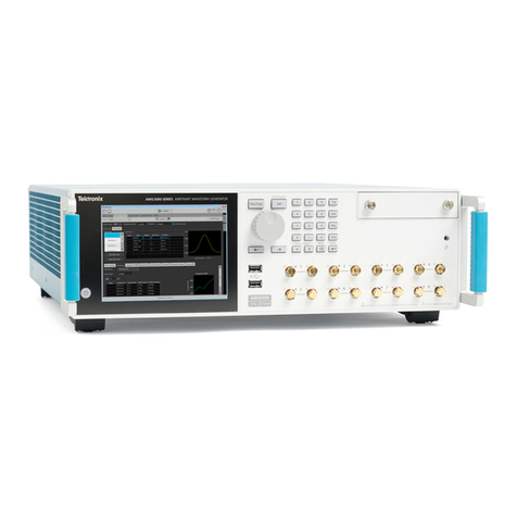
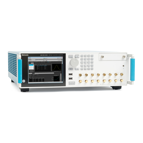
Tektronix AWG5000 Series User manual

Tektronix

Tektronix AWG5000 Series User manual

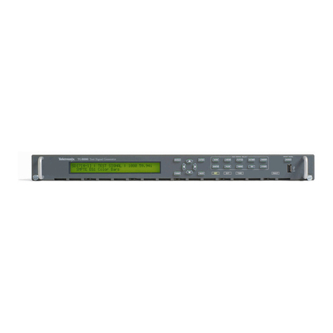
Tektronix Tektronix SPG8000 Installation and maintenance instructions

Tektronix

Tektronix Tektronix SPG8000 Installation and maintenance instructions

Tektronix TG8000 User manual

Tektronix

Tektronix TG8000 User manual

Tektronix AWG5012 User manual

Tektronix

Tektronix AWG5012 User manual

Tektronix AWG7000B Series User manual

Tektronix

Tektronix AWG7000B Series User manual

Tektronix VITS 200 User manual

Tektronix

Tektronix VITS 200 User manual

Tektronix AWG5204 User manual

Tektronix

Tektronix AWG5204 User manual

Tektronix AWG2005 User manual

Tektronix

Tektronix AWG2005 User manual

Tektronix AWG5000B Series User manual

Tektronix

Tektronix AWG5000B Series User manual

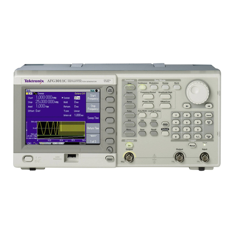
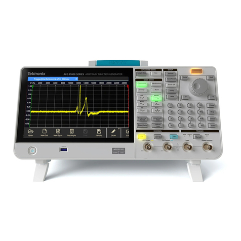
Tektronix AFG3000 Series User manual

Tektronix

Tektronix AFG3000 Series User manual

Tektronix SG 504 User manual

Tektronix

Tektronix SG 504 User manual

Tektronix HDLG7 User manual

Tektronix

Tektronix HDLG7 User manual

Tektronix AFG3000 Series Use and care manual

Tektronix

Tektronix AFG3000 Series Use and care manual

Tektronix AWVG1 User manual

Tektronix

Tektronix AWVG1 User manual

Tektronix FG501 User manual

Tektronix

Tektronix FG501 User manual

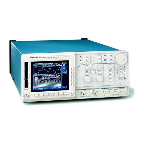
Tektronix AWG610 User manual

Tektronix

Tektronix AWG610 User manual

Tektronix AWG5200 Series User manual

Tektronix

Tektronix AWG5200 Series User manual

Tektronix TSG 95 User manual

Tektronix

Tektronix TSG 95 User manual

Tektronix AWG 2021 User manual

Tektronix

Tektronix AWG 2021 User manual

Tektronix AWG520 User manual

Tektronix

Tektronix AWG520 User manual

Tektronix FG501 User manual

Tektronix

Tektronix FG501 User manual

Tektronix AFG3000C Series Use and care manual

Tektronix

Tektronix AFG3000C Series Use and care manual

Tektronix FG 5010 User manual

Tektronix

Tektronix FG 5010 User manual

Tektronix AWG410 User manual

Tektronix

Tektronix AWG410 User manual

Popular Portable Generator manuals by other brands

Claind Nitro70 user manual

Claind

Claind Nitro70 user manual

Nanni Q1500 Series user manual

Nanni

Nanni Q1500 Series user manual

Grupel COMAP INTELITE NT AMF 25 Basic user manual

Grupel

Grupel COMAP INTELITE NT AMF 25 Basic user manual

Snapper 30214 Operator's manual

Snapper

Snapper 30214 Operator's manual

Allmand MAXI-POWER 25 Operator's manual

Allmand

Allmand MAXI-POWER 25 Operator's manual

Z.I.P.P.ER MASCHINEN ZI-STE2800IV user manual

Z.I.P.P.ER MASCHINEN

Z.I.P.P.ER MASCHINEN ZI-STE2800IV user manual

EMB MFG Wallenstein HUF12000E OPERATOR'S MANUAL AND PARTS LISTING

EMB MFG

EMB MFG Wallenstein HUF12000E OPERATOR'S MANUAL AND PARTS LISTING

iPower GXS4300i owner's manual

iPower

iPower GXS4300i owner's manual

Champion CPG4000DHY-DF-EU Operator's manual

Champion

Champion CPG4000DHY-DF-EU Operator's manual

Sportsman GEN7500TRI Step-by-step guide

Sportsman

Sportsman GEN7500TRI Step-by-step guide

Miller ENPAK owner's manual

Miller

Miller ENPAK owner's manual

Master LP 10 kW M Operation and maintenance manual

Master

Master LP 10 kW M Operation and maintenance manual

Craftsman 580.327182 Operators Operator's manual

Craftsman

Craftsman 580.327182 Operators Operator's manual

Generac Portable Products GP Series owner's manual

Generac Portable Products

Generac Portable Products GP Series owner's manual

Shindaiwa 1 Series Operator's manual

Shindaiwa

Shindaiwa 1 Series Operator's manual

Sonnen sonnenProtect 2500 Operating instructions for operators

Sonnen

Sonnen sonnenProtect 2500 Operating instructions for operators

Category 5 41535 Owner's manual & operating instructions

Category 5

Category 5 41535 Owner's manual & operating instructions

Ice 18ZR Operation and maintenance manual

Ice

Ice 18ZR Operation and maintenance manual

manuals.online logo
manuals.online logoBrands
  • About & Mission
  • Contact us
  • Privacy Policy
  • Terms and Conditions

Copyright 2025 Manuals.Online. All Rights Reserved.