Advance acoustic AXIS AX Owner's manual

www.advancedco.com
Front Panel Programming Manual

www.advancedco.com
2
Table of Contents Page
1INTRODUCTION / OVERVIEW............................................................................................................................4
1.1LIMITATIONS OF FIRE ALARM SYSTEMS ...........................................................................................................4
1.2GENERAL INSTALLATION NOTES .....................................................................................................................4
2PROGRAMMING..................................................................................................................................................5
2.1INTRODUCTION ...............................................................................................................................................5
2.1.1Access Levels ..........................................................................................................................................5
2.2MEMORY LOCK...............................................................................................................................................6
2.3STARTING POINT ............................................................................................................................................7
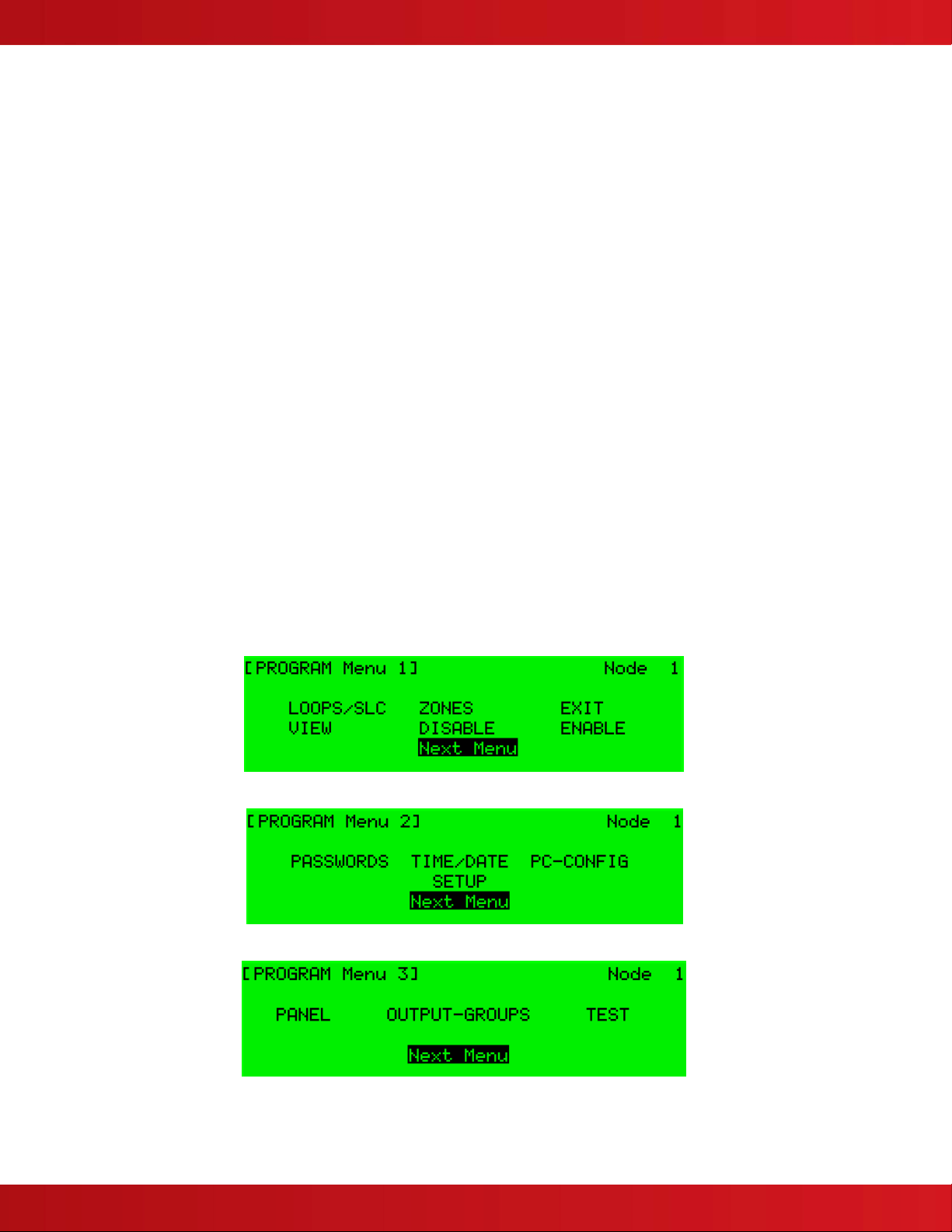
2.3.1Program Menu Screens ...........................................................................................................................8
2.3.2Navigating Through Menus......................................................................................................................9
2.3.3Changing Text Descriptions.....................................................................................................................9
2.3.4Numeric data entry.................................................................................................................................11
2.4RECOMMENDED PROGRAMMING PROCEDURE ................................................................................................11
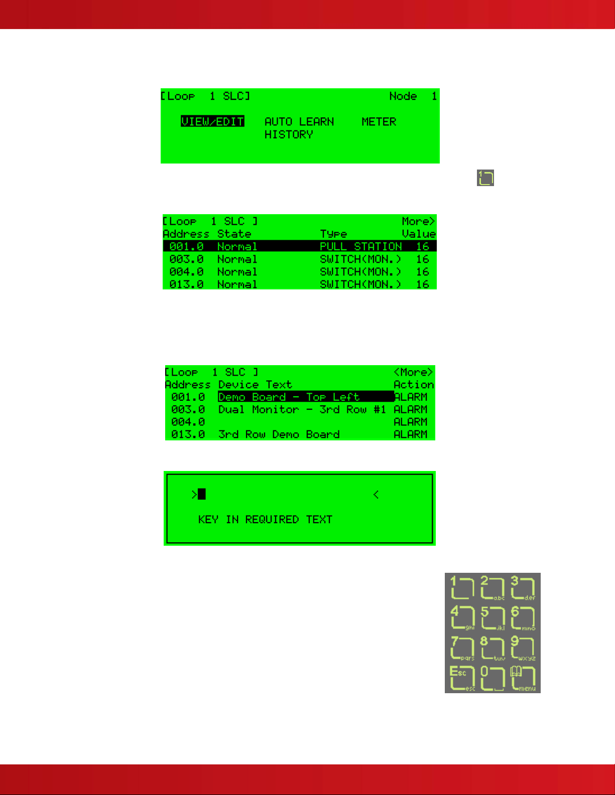
2.4.1Loops/SLC .............................................................................................................................................13
2.4.1.1Loop – View/Edit...........................................................................................................................................13
2.4.1.1.1Address Parameter..................................................................................................................................13
2.4.1.1.2State Parameter.......................................................................................................................................13
2.4.1.1.3Type.........................................................................................................................................................13
2.4.1.1.4Value Parameter......................................................................................................................................14
2.4.1.1.5Zone Parameter.......................................................................................................................................14
2.4.1.1.6Device Text Parameter ............................................................................................................................14
2.4.1.1.7Action Parameter.....................................................................................................................................14
2.4.1.1.8Sensitivity Parameter...............................................................................................................................15
2.4.1.1.9O/P Group ...............................................................................................................................................18
2.4.1.1.10Additional Info.........................................................................................................................................18
2.4.1.1.11Detector Testing .....................................................................................................................................19
2.4.1.2Loop – Auto Learn........................................................................................................................................20
2.4.1.2.1Normal Procedure / Auto Learn ...............................................................................................................20
2.4.1.2.2Procedure if the Panel finds Devices Missing..........................................................................................20
2.4.1.2.3Procedure if the Panel finds Devices Added............................................................................................21
2.4.1.2.4Procedure if the Panel finds Devices Changed........................................................................................21
2.4.1.3Loop – Meter ................................................................................................................................................22
2.4.1.4Loop – History ..............................................................................................................................................22
2.4.2Zones .....................................................................................................................................................22
2.4.3Exit .........................................................................................................................................................23
2.4.4View........................................................................................................................................................23
2.4.5Disable ...................................................................................................................................................23
2.4.6Enable ....................................................................................................................................................23
2.4.7Passwords..............................................................................................................................................24
2.4.8Time and Date........................................................................................................................................24
2.4.9PC Config...............................................................................................................................................25
2.4.10Setup..................................................................................................................................................25
2.4.10.1Network ........................................................................................................................................................25
2.4.10.2Panel Zone ...................................................................................................................................................25
2.4.10.3Onboard NACs .............................................................................................................................................25
2.4.10.4Service Number............................................................................................................................................25
2.4.10.5Service Due Date .........................................................................................................................................25
2.4.10.6Trace Logging Mode.....................................................................................................................................26
2.4.10.7Detector Blinking ..........................................................................................................................................26
2.4.10.8Ground Monitoring........................................................................................................................................26
2.4.10.9DACT............................................................................................................................................................27
2.4.10.10DACT AC Trouble Delay..........................................................................................................................27
2.4.10.11Resound Upon.........................................................................................................................................27
2.4.10.12CONFIG Data ..........................................................................................................................................27
2.4.11Panel..................................................................................................................................................27
2.4.12Output-Groups ...................................................................................................................................28
2.4.12.1Default Output Settings ................................................................................................................................28

www.advancedco.com
www.advancedco.com 3
2.4.12.2Cause .......................................................................................................................................................... 29
2.4.12.3Style............................................................................................................................................................. 30
2.4.12.3.1Delay...................................................................................................................................................... 30
2.4.12.3.2Mode...................................................................................................................................................... 30
2.4.12.3.3Wait........................................................................................................................................................ 31
2.4.12.4Copying Output Settings to Multiple Zones.................................................................................................. 31
2.4.13Positive Alarm Sequence Delays ......................................................................................................31
3APPENDICES.....................................................................................................................................................32
3.1APPENDIX 1–FORGOTTEN LEVEL 3PASSWORD ...........................................................................................32

www.advancedco.com
4
1 Introduction / Overview
This manual covers the front panel programming of the AxisAX Intelligent Fire Alarm Control Panels.
1.1 Limitations of Fire Alarm Systems
An automatic fire alarm system can provide an
early warning and notification of the development
of a fire. It cannot, however, insure protection
against loss of property or loss of life.
It is recommended that smoke and heat detectors
as well as notification appliances, be located
throughout the building in accordance with the
requirements detailed in NFPA 72, any local / state
codes and with the instructions supplied with the
equipment.
The type(s) of detector(s) employed and their
physical location must be chosen carefully to
ensure that they detect the types of fires likely to
occur in the protected area.
Even so, a number of factors may prevent the
necessary levels of combustion products from
reaching the sensing chambers and thus the
system may not indicate an alarm condition.
Heat detectors protect property, not life.
Smoke detectors shall be installed in the same
room(s) as the FACP, any equipment used for
transmission of the alarm condition, and in
locations where power supplies are mounted.
Otherwise, a developing fire may damage the
system and its ability to report the fire alarm
condition. Refer to NFPA 72.
The system will not operate without power.
Standby batteries shall be properly maintained and
replaced regularly.
Regular maintenance will insure that the system is
operating at its optimum performance. Arrange a
maintenance agreement with the manufacturer’s
local representative to insure that the system is
maintained by a professional fire alarm installer in
accordance with National and any local / state
codes. Maintain a written record of all inspections
and maintenance performed.
1.2 General Installation Notes
WARNING: Disconnect all sources of power (AC
and Battery) before installing components or
servicing the system.
DO NOT install / remove circuit cards while the
FACP is supplied with power (either AC or
Battery).
ENVIRONMENT: INSTALL the equipment in a
clean, dry environment.
The equipment meets the requirements for
operation at 32°F - 120°F (0°C - 49°C) and relative
humidity of 85% RH. However, standby battery life
is drastically reduced at higher temperatures. The
recommended room temperature for installation is
60°F - 86°F (15°C - 27°C).
WIRING: CHECK that the installation wire sizes
are adequate to deliver the required load current
and maintain compatibility with the specific device
operating voltages.
USE an anti-static wrist strap
whenever handling circuit cards.
STORE circuit cards in static
suppressive packaging.
CAUTION: Acceptance / Re-acceptance Tests
Following installation, or after any system change
(including changes to operating software or
configuration settings), the system shall be tested
in accordance with the requirements in NFPA 72
and any local / state codes.
All affected functions or devices shall be 100%
tested. In addition, at least 10% of initiating devices
not directly affected by the change shall also be
tested.
Follow the recommendations of NFPA 72.
A secure dedicated ground connection
is required. Although no system is
immune to the effects of lightning
strikes, a secure ground connection
will reduce susceptibility. The use of
overhead or outside aerial wiring is not
recommended
General guidance for installation
and trouble free operation.
Must be
Grounded
ATTENTION
OBSERVE PRECAUTIONS
FOR HANDLING
ELECTROSTATIC
SENSITIVE DEVICES

www.advancedco.com
www.advancedco.com 5
2 Programming
864
Where you see this symbol
take note of any special UL
864 9th Edition precautions. PC
ONLY
Where you see this symbol, there are
additional enhanced features that can
only be configured using the PC-NeT,
Field Configuration Program.
NOTICE TO USERS, INSTALLERS, AUTHORITIES HAVING JURISDICTION AND OTHER INVOLVED PARTIES:
This product incorporates field programmable software. In order for the product to comply with the
requirements in the Standard for Control Units and Accessories for Fire Alarm Systems (UL 864, 9th Edition),
certain programming features or options must be limited to specific values or not used at all as indicated
below.
Program feature or
option
Permitted
in UL 864?
Y/N
Possible Settings Settings permitted in
UL 864
Section Ref.
Positive Alarm
Sequence
Y Stage 1: 1-300 seconds
Stage 2: 1-300 seconds
Stage 1: 15 seconds
Stage 2: 180 seconds
See Installation
and Operation
Manuals
Alarm Verification Y Fixed N/A
Multiple Detector
Operation
Y Per Zone Per Zone 2.4.12
2.1 Introduction
These instructions explain the configuration and front panel programming of the AxisAX Intelligent Fire Alarm Control
Panel.
2.1.1 Access Levels
Access to the panel’s control buttons and switches is restricted. A key must be used to unlock a secured cabinet
door to gain access to the controls or in the case of the AX-CTL-1 to enable use of the controls. The panel
operation is further protected from inadvertent and erroneous misuse by means of four access levels.
These levels are as follows:
Level 1 Untrained User – Assigned by Level 3 User, allows restricted access to system controls.
Level 2 Authorized User – Assigned by Level 3 User, allows full access to system controls.
Level 3 Programming – High level, factory authorized technician/engineer, permitting programming of all
system features and functions.
Level 4 Firmware Upgrade– Highest level, factory authorized technician/engineer. Permits flash programming of
system software. Special Tools Required.
A level 3 PROGRAM password is required to enter all of the PROGRAMMING menus. For further details of
Passwords, refer to Section 0.
Level 3 PROGRAM Password:
If this password number is lost or forgotten, it is not possible to enter
program/commission functions. Refer to 3.1 for further information.

www.advancedco.com
6
2.2 Memory Lock
The configuration memory, which contains all programmed entries, may be
protected against inadvertent change by means of a memory lock. The
memory lock is J1 located to the far left of the main “Base Card” PCB.
Before making any programming/configuration data changes, ensure the
jumper is in the OPEN (unlocked) position.
After all changes have been made, move the jumper back to the CLOSED
(locked) position to protect the memory against inadvertent change.
Refer to the diagram opposite and below for position of jumper settings.

www.advancedco.com
www.advancedco.com 7
2.3 Starting Point
Upon power up, the panel display will show:
2:30 PM
DEC 22 2010
NORMAL PANEL OPERATION
(Press Menu to View)
To access programming press the MENU button on the keypad. The following will be displayed:
Scroll to the TOOLS heading and press the✔button or press the number 6 on the keypad. The following will
be displayed:
Press the ✔button or press the number 1 on the keypad. The following will be displayed:
Enter the factory default Level 3 programming code 7654, and press the✔button to enter the password. You are
now in Level 3 programming mode and the screen below will be displayed:

www.advancedco.com
8
There are three programming menu screens to choose from with up to 13 different sub-menus. The 13 sub-menus
are as follows:
LOOPS/SLC: Identify number of SLC/LOOPS installed. Perform AUTO-LEARN, Alter/enter device text, and
more. In addition, opens several sub-menus.
ZONES: Lists all zones in use by the system and allows text alterations.
EXIT: Exits program mode and returns to normal display/operation.
VIEW: View status of the entire system. In addition, opens several sub-menus.
DISABLE: Disable Zone/Inputs, Outputs and Groups.
ENABLE: Enable of Zone/Inputs, Outputs and Groups.
PASSWORDS: Enter/change level 1, 2, 3 and 4 passwords.
TIME/DATE: Change/set the time and date.
PC CONFIG: Enables connection to a PC for use of PC-NeT Configuration Tool.
SETUP: Allows programming of a number of system options including networking, service due date,
on-board NAC circuit configuration, detector device blinking and more.
PANEL: Lists all internal panel circuits and allows programming from default settings.
OUTPUT-GROUPS: Create limited output cause and effect programming.
TEST: Test Zones, Display, Buzzer, Printer and Outputs.
2.3.1 Program Menu Screens
Program Menu 1:
Program Menu 2:
Program Menu 3:
Selecting “Next Menu” alternates between Program Menu 1, 2 and 3.

www.advancedco.com
www.advancedco.com 9
2.3.2 Navigating Through Menus
When a Program Menu is displayed, use the buttons to highlight the required menu option and then press
the ✔button to select that option. More Program Menu options are available by selecting the “Next Menu” button.
Press the ‘Esc’ button from within any menu option to return to the previous menu.
The system can be returned to Normal Operation by pressing the ‘Esc’ button to return to the top level Program
Menu 1, then select “EXIT” and enter your password.
2.3.3 Changing Text Descriptions
Various parameters can have a user defined text description. These include SLC loop devices, zones, outputs, etc.
The zone and device text descriptions are shown on the display when a status change occurs, providing a quick
and clear indication of the source of the problem.
Example:
To add or change the device text associated to an addressable point, highlight the LOOPS/SLC in [Program Menu
1] and then press the ✔button or press the number 1 on the keypad.
Then, highlight the LOOP associated with the addressable point (i.e.: LOOP 1), then press the ✔button.
Press the buttons to scroll through the list of loops and then press the ✔button or use the number keypad
(Loop 1 = 1, Loop 2 = 2, Loop 3 = 3 and Loop 4 = 4) to select the required loop.
Note: The list of loops available will be adjusted automatically to show only those loops that have a loop
driver installed. The below example is for an AxisAX Intelligent Fire Alarm Control Panel with four loop
drivers (AX-CTL-4 [4 SLC Loops]) installed. If the above were a 2 loop driver system (AX-CTL-2) loops 3
and 4 would have an x mark in place of the check mark.

www.advancedco.com
10
The display will then show a list of programming options for the specific loop selected, as follows:
Highlight the VIEW/EDIT programming option and then press the ✔button or press the number 1 on the
keypad. The display will be as follows:
Press the buttons to scroll to the required address point then press the button until you reach the “Device
Text” column.
Note: If no previous Device Text has been programmed, Device Text location will be blank as indicated for
device 4 below:
Press ✔button, the following will be displayed awaiting entry of user text:
The method of entering the characters is similar to the method employed on cell phones. The
number buttons provide both their appropriate number and several letters of the
alphabet. An example of the keypad is shown opposite.
For example, Button 2 allows entry of the number 2 and letters A, B and C.
When a button is pressed, the number is first shown on the display at the current cursor
position. If the button is pressed again within ½ second, the first character replaces the
number. A further press displays the second available character and so on. After
pressing the button to obtain the required character, wait for 1-second and the character
will be entered and the cursor will move to the next character in the text description.
Pressing another button will immediately enter the previous character and move the
cursor on to the next character.
Use the buttons to move backwards or forwards along the device text line. When you’ve completed entering
the device text description, press the ✔button.

www.advancedco.com
www.advancedco.com 11
After completing all addressable point device text descriptions, press the ‘Esc’ button to return to the previous
display.
The following table shows the numbers, characters and symbols assigned to each button on the keypad.
Button 1st Press 2nd Press 3rd Press 4th Press 5th Press Further Characters
1 1
2 A B C 2 Ä, Æ, Å, À, Á, Â, Ã, Ç
3 D E F 3 È, É, Ê, Ë, Đ
4 G H I 4 Ì, Í, Î, Ï
5 J K L 5
6 M N O 6 Ö, Ø, Ò, Ó, Ô, Õ, Ñ
7 P Q R S 7
8 T U V 8 Ù, Ú, Û, Ü
9 W X Y Z 9 Ý, Þ
0 Blank 0
Alternatively, press the buttons to scroll through a list of characters. Start by pressing the “up arrow” key. When
the required character is shown, press the button to move on to the next character. The list of characters
available and the order of presentation is as follows:
Blank !“#$%&‘()*+,-./ 0123456789 :;?@ ABCDEFGHIJKLMNOPQRSTUVWXYZ [‘]^_
2.3.4 Numeric data entry
Numbers are entered by moving to the required field, and then typing in the required number, followed by the ✔
button.
If the number is entered incorrectly, press the ‘Esc’ button to restore the previous number.
2.4 Recommended Programming Procedure
Step 1 – SET-UP, define general set-up information.
Step 2 – PASSWORDS, define user and program passwords as required.
Step 3 – AUTO-LEARN, learn the devices on the specific loop.
Step 4 – VIEW, enter zone numbers, location text and change output group assignments if required.
Step 5 – OUTPUTS, program output groups as required.
Step 6 – ZONES, enter zone text as required.

www.advancedco.com
12
PROGRAM Menu Functions
The following table gives a list of the PROGRAM Menu Functions, the sub-functions available within each main
function and a brief description for each function.
Step No./Main
Menu Option Sub Menus Comments
3
4
LOOPS/SLC View/Edit View, test and configure the SLC loop devices
Auto Learn Learn the devices present on all SLC loops
Meter View information on the SLC loop voltages /currents
History View the history of attached SLC devices
6 ZONES -- Configure the Zones
EXIT -- Cancel Level 3 Access and return to Level 2 Menu Options
VIEW (Allows
viewing of any
programming
changes and
system status
without exiting
program mode.)
Alarms View zones and inputs that are in alarm
Off-Normal View off-normal alarms, supervisory, troubles, disables, pre-alarms and warnings
Network View network communications/diagnostics
Inputs View input devices
Outputs View output devices
Log View event log all events or alarm only
Panel View hardware (panel voltages and currents) and software (module revisions)
DISABLE Zone/Inputs Disable zone (s) or specific inputs
Outputs Disable outputs by type or by specific output
Groups Disable created disablement group
ENABLE Zone/Inputs Enable disabled zone (s) or specific disabled inputs
Outputs Enable disable outputs by type or by specific disabled output
Groups Enable disabled group
2 PASSWORDS -- Configure the Level 2 and Level 3 passwords
TIME/DATE -- Change time and date
PC-CONFIG -- Enable PC transfer of configuration data to the panel
1 SETUP -- Configure general operating parameters
PANEL -- Change the default zone assignments and output groups for all panel I/O’s
5 OUTPUT-GROUPS -- Configure the operating characteristics of output groups
TEST Test zones, display, buzzer, printer and outputs

www.advancedco.com
www.advancedco.com 13
2.4.1 Loops/SLC
Upon selecting the LOOPS/SLC option, the display will prompt for selection of the loop to be viewed / programmed.
Note: The list of loops available will be adjusted automatically to show only those loops that have a loop
driver installed. The above example is for an AxisAX Intelligent Fire Alarm Control Panel with four loop
drivers (AX-CTL-4 [4 SLC Loops]) installed. If only two loop drivers (AX-CTL-2 [2 SLC Loops]) were
available loops 3 and 4 would have an x in place of the check mark.
Press the buttons to scroll through the list of loops available and then press the ✔button to select the loop
required. The display will then show a list of programming options for the available loop as follows:
2.4.1.1 Loop – View/Edit
The VIEW/EDIT option shows a list of the devices connected to the loop that were Auto Learned by the panel. For
example:
The first device on the loop is shown at the top of the list and is highlighted. Press the buttons to scroll through
the list of devices.
Press the buttons to view additional information. The display highlights a particular parameter. If a highlighted
field is modifiable press the ✔button and an additional option menu will be displayed.
2.4.1.1.1 Address Parameter
Shows address of device on loop/SLC being viewed.
2.4.1.1.2 State Parameter
This parameter shows the current operational status of the device. For example, this can show Normal, Alarm,
Device Missing, etc.
This parameter cannot be changed.
2.4.1.1.3 Type
This parameter shows the type of device Auto Learned by the panel. For example, this can show Pull Station, Multi-
Sensor, Photo Smoke, Heat, etc.
This parameter cannot be changed.

www.advancedco.com
14
2.4.1.1.4 Value Parameter
This parameter shows the analog value returned by the device. The number displayed will vary according to the
type of device installed. An ‘H’ (High) and ‘L’ (Low) is shown for Switch (logic) inputs. The current sensitivity mode
setting for intelligent smoke detectors is shown (a value based on sensitivity programming ranges 1 through 5).
This parameter cannot be changed.
2.4.1.1.5 Zone Parameter
This parameter shows the zone to which this device has been assigned. Use the number keys to change the zone
assigned to the device and press the ✔button.
2.4.1.1.6 Device Text Parameter
This parameter shows the 26-character location text assigned to this device. For guidance on how to change the
text, refer to Section 2.3.3.
2.4.1.1.7 Action Parameter
This parameter shows the action that will be performed when this device indicates an active (alarm) condition. For
example:
Press the ✔button to change the action assigned to this input device. A pop-up window is then shown on the
display from which a different action can be selected.
Press the buttons to scroll through the list of actions and then press the ✔button to confirm the change. The
display reverts to the device list showing the new action assigned to this device. Alternatively, press the ‘Esc’
button to cancel the changes and return to the device list display. The following actions are available (additional
actions are available on a PC-NeT, Field Configuration Program).

www.advancedco.com
www.advancedco.com 15
Action Description
Alarm Signal1An alarm condition will be generated whenever the input is active.
Supervisory A supervisory condition will be generated whenever the input is active.
Trouble Signal A trouble condition will be generated whenever the input is active.
Pre-Alarm A pre-alarm condition will be generated whenever the input is active.
Key Lock Enables / inhibits front panel controls (Silence, Acknowledge, Reset etc.)
Control Signal Allows control of outputs without displaying a status event or sounding the panel buzzer
- No action assigned to the input.
P
P
C
C
O
ON
NL
LY
Y
Other device actions can be configured using the PC-NeT Configuration Tool.
2.4.1.1.8 Sensitivity Parameter
This parameter shows if the device sensitivity is set to its “DEFAULT” or “CUSTOM” settings. See below:
Press the ✔button to change the sensitivity assigned to an input device. When selected, a new screen displays the
sensitivity settings assigned. For example, with an Intelligent Photoelectric Detector:
Press the buttons to highlight the required menu option and then press the ✔button to select it. Use the
number buttons to enter the required value. Alternatively, press the ‘Esc’ button to cancel the changes.
Note: The alarm thresholds are fixed for all devices. Sensitivity can only be changed for detectors using the
sensitivity mode setting.
2.4.1.1.8.1 Mode
Each intelligent detector is capable of being field programmed for one of five response/sensitivity modes (see
below). Response modes correspond to unique response behaviors of a detector and the type of environment it is
protecting, which can be broadly related to the characteristics of a fire. The detector response modes relate to
different combinations of smoke sensitivity characteristics and programmable assessment times. Response mode
1 is more sensitive than response mode 5. Detectors set to response mode 1 would be more suitable for
environments in which sources of unwanted alarms are rare (i.e.: clean rooms and computer rooms). Response
mode 5 set detectors would be suitable for more dusty or harsh environments (i.e.: boiler rooms, loading dock
1Alarm Conditions are latched. By default, all other conditions are non-latching. The action for smoke and certain other detectors is always alarm
and cannot be changed.

www.advancedco.com
16
areas). Response mode 3 (default programmed) would be the mid-sensitivity level used for most normal
applications. Response mode setting and hysteresis of the individual detectors are stored within the detector’s
memory. The storing of this critical information in the detector rather in the fire alarm control panel software allows
the detector to maintain its programmed response settings and compensated values even when power is removed
from the detector. If the detector is powered down or inadvertently placed in another location, the detector
response mode and clean values are not lost.
Clean Room,
Computer
Room
Hotel Room,
Apartment Office,
Hospital Ward,
Factory,
Light Industry
Warehouse,
Restaurant Loading Dock,
Parking Garage Kitchen, Laundr
y
(enclosed and
ventilated)
Boiler Room
Mode 1 2 3 4 5 1 2 3 4 5 1 2 3 4 5 1 2 3 4 5 1 2 3 4 5 1 2 3 4 5 1 2 3 4 5
Photoelectric
Ionization
Multi-Senso
r
Heat
1, 2, 3, 4, 5 = Response/Sensitivity Modes
= Mode Suitable for Installation
Photoelectric Detecto
r
Multi-Sensor Detecto
r
Response
Mode
Sensitivity
Characteristics
Programmable
Assessment
Time
Response
Mode
Smoke Sensitivity
Characteristics
Temperature
Sensitivity
Programmable
Assessment
Time
1 1.7 %/ft 5 sec 1 1.7 %/ft High 0-20 sec
2 1.7 %/ft 30 sec 2 2.3 %/ft None 0-30 sec
3 2.3 %/ft 5 sec 3 2.7 %/ft Medium 0-20 sec
4 2.3 %/ft 30 sec 4 3.3 %/ft Medium 0-20 sec
5 2.9 %/ft 5 sec 5 None 135
0
F 0-30 sec
Ionization Detecto
r
Heat Detecto
r
Response
Mode
Sensitivity
Characteristics
Programmable
Assessment
Time
Response
Mode
UL521 Temperature
Rating (0F)
Sensitivity
Characteristics
Spacing
1 .60 %/ft 5 sec 1 135
0
Ordinary Static/Rate-of-Rise 70 ft
2 .60 %/ft 30 sec 2 150
0
Ordinary Static/Rate-of-Rise 70 ft
3 .65 %/ft 5 sec 3 150
0
Ordinary Static 70 ft
4 .65 %/ft 30 sec 4 200
0
Intermediate Static/Rate-of-Rise 70 ft
5 .70 %/ft 5 sec 5 200
0
Intermediate Static 70 ft

www.advancedco.com
www.advancedco.com 17
2.4.1.1.8.2 Sampling
If an intelligent device is in alarm the AxisAX Intelligent Fire Alarm Control Panel will perform multiple assessments
of the alarming device to ensure that the alarm condition from the device is valid. The value of the assessment time
can be programmed by the installer during installation. Programmable assessment time fields range from 0 to a
maximum of 10 seconds (0 to 20/30 seconds for Multi-Sensor detectors) from the first report of an alarm condition
to the final validated (assessed) alarm condition. Refer to Front Panel Programming Manual or PC-NeT Field
Configuration Programming Manual for further explanation.
Note: Programmed default values for assessment time:
Detectors: Default 5 seconds. Maximum 10 seconds.
Input Modules: Default 0 seconds. Maximum 10 seconds.
2.4.1.1.8.3 Alarm
When an intelligent device enters an alarm condition the analog value of the device can be viewed by the panel’s
graphical display. Analog values for alarm are set at a value of 55. If an intelligent device falls below a minimum
analog value the AxisAX Intelligent Fire Alarm Control Panel will enter a trouble/fault warning (i.e.: dirty detector)
condition for that specific device. Trouble/fault warning value is normally set at a value of 8 with a programmable
range of 4-20.
The alarm level is the level of the analog value returned by the detector at which the panel will enter an alarm
condition. The default value is 55.
Note: The alarm level cannot be adjusted.
2.4.1.1.8.4 Pre‐Alarm
The pre-alarm level is the level of the analog value returned by the detector at which the panel will enter a pre-alarm
condition the pre-alarm value is defaulted to 45; this field is programmable and can be set at a lower or higher level.
Note: If pre-alarm indication is not wanted, set the pre-alarm value to 55, which equals the alarm value. No
pre-alarm signal will be generated.
2.4.1.1.8.5 MinimumValue
If the detector analog value falls below the minimum analog value programmed the AxisAX Intelligent Fire Alarm
Control Panel will enter a trouble/fault warning (i.e.: dirty detector) condition. Trouble/fault warning value is normally
set at a value of 8 with a programmable range of 4-20.
2.4.1.1.8.6 SpecialSensitivityModeSSM/Clock
In addition to the “SENSITIVITY ADJUST MODE”, an intelligent device can also run “SPECIAL SENSITIVITY
MODE” (SSM) under time-clock control.
Note: The AxisAX Intelligent Fire Alarm Control Panel can support 10 independent, 7-day time clocks.
With the SAM/SSM Option highlighted, press the ✔button to view the Special Sensitivity Mode settings. For
example:
In the above example the panel is using special sensitivity mode 1 (and time clock number 2). Enter “0” in the
SSM/Clock field to cancel Special Sensitivity Mode.
A number must be entered in the SSM/Clock field to select the appropriate SSM number and time clock. To view
the time clock settings, highlight the SSM/Clock field, and press the ✔button.
USE CAUTION WHEN
SELECTING SAMPLING VALUE

www.advancedco.com
18
For example:
The panel supports two independent times for each day of the week during which the SSM mode will be switched
on (i.e. during which the Special Sensitivity Mode settings are active).
In the above example the SSM will be active between 7:00 PM on Monday and 6:30 AM on Tuesday (an example of
use, would be a detector more sensitive during none occupied time periods).
Press the buttons to select the appropriate time field and use the number buttons to enter the required
times. Press the ‘Esc’ button to return to the previous menu display.
Every type of device (the device type is shown in the top, right hand corner of the display) can support a unique
SSM setting based on an SSM/Clock number. In the previous example the Special Sensitivity Mode settings have
been defined for a PHOTO SMOKE that is using SSM/Clock number 2. If other intelligent smoke detectors on the
same panel also require the same settings, then you only need to set them to the SSM/Clock 2 also. If a different
time setting is required simply set another SSM/Clock number to meet its requirement.
2.4.1.1.9 O/P Group
The O/P Group assignment is a group assigned to addressable NAC and relay modules. These output groups
determine the manner in which the outputs will operate when an alarm or other status event occurs within the
system.
For example:
Use the number buttons to change the value of the O/P Group setting.
By default, all NAC loop output devices are assigned to output group 1 (common alarm, drill, walk test and
silenceable) and all relay loop output devices are assigned to output group 199 (common alarm).
For detailed information and guidance on the programming and use of output groups, refer to Section 2.4.12
2.4.1.1.10Additional Info
This parameter shows additional information for the intelligent smoke detectors (✔indicates additional information
available). For example:
The panel can read any of the extended memory locations within the intelligent smoke detectors.

www.advancedco.com
www.advancedco.com 19
Highlight any ✔marked device:
View the devices drift, rapidly compensate it or view the EEPROM. Below is an example of viewing drift. Each
intelligent smoke detector connected to the specific SLC loop will indicate its drift as it relates to detector
compensation, 0 being the cleanest, 100 being dirty.
2.4.1.1.11Detector Testing
Individual detectors can be tested to check the chamber response/operation and illuminate the detector LED.
While the address field is highlighted, press the buttons to scroll through the list of devices to the desired
detector (or key in the address, and then press the ✔button).
A menu will appear to confirm that you want “Test This Detector”.
Press the ✔button to confirm or press the ‘Esc’ button to cancel.
Once selected, commands are sent to the intelligent smoke detector to turn on the detector LED and put the
chamber into test. The “Test” LED lights up and the panel display returns to the list of devices.
After a few seconds the analog signal will rise, indicating the level of an alarm condition. If the detector is then left in
the test condition, the Detector State will change to a “Fire Test” status.
The test is cancelled as soon as the display is scrolled up or down or when the ‘View/Edit’ area is exited.

www.advancedco.com
20
2.4.1.2 Loop – Auto Learn
2.4.1.2.1 Normal Procedure / Auto Learn
The panel can automatically learn the presence or absence of devices at all addresses connected to a specific SLC
loop (Auto Learn is done on a per loop basis). When the Auto Learn option is selected, the panel starts searching
the selected SLC loop for all associated addressable devices. A display is shown to indicate the progress of this
procedure.
For example:
When all addresses have been searched and all devices found the panel will display a summary screen showing
the quantity of devices found for each type of device, as indicated below:
This summary provides a quick check to ensure that the panel has found all of the devices that should be
connected to the SLC loop.
Press the ‘Esc’ button to return to the loop menu and press “Esc” again to go to the select SLC loop main menu.
Upon completion of the Auto Learn programming, all devices will be default programmed for general alarm:
NACs: activate on any alarm condition, silenceable
Relays: activate on any alarm condition, non silenceable
Smoke Detectors: default sensitivity (Mode 3) setting/level
Outputs = relay
Inputs = contact device input
2.4.1.2.2 Procedure if the Panel finds Devices Missing
When the panel cannot communicate with a device previously programmed into the panel, the Auto Learn process
is suspended and the display shows a pop-up window with options, as indicated below:
If the missing device is kept (or all missing devices are kept), the panel remembers the programming for these
devices. The panel will report a trouble condition until such time as the missing devices are reconnected.
If the missing device is deleted (or all missing devices are deleted), the panel clears all previous programming for
these devices. This includes any sensitivity threshold changes, text assignments, zone assignment, action, etc.
Table of contents
Popular Control Panel manuals by other brands

Xantrex
Xantrex Link 1000 owner's guide

Balboa Water Group
Balboa Water Group BP2 Series User Interface and Programming Reference

DSC
DSC Envoy NT9010DMK installation instructions

Swisson
Swisson XMG-51 user manual

Dometic
Dometic MPC01 Installation and operating manual

IDTECK
IDTECK Star iCON100 Quick installation guide

Hornby
Hornby 'Select' Unit Operator's manual

Global Fire Equipment
Global Fire Equipment JUNIOR MINI-REP installation manual

AUDAC
AUDAC WP205 user manual

Beckhoff
Beckhoff CPX29 0000 Series Installation and operating instructions

JCM Technologies
JCM Technologies ROLL868 DMR quick start guide

GE
GE Multilin 889 instruction manual