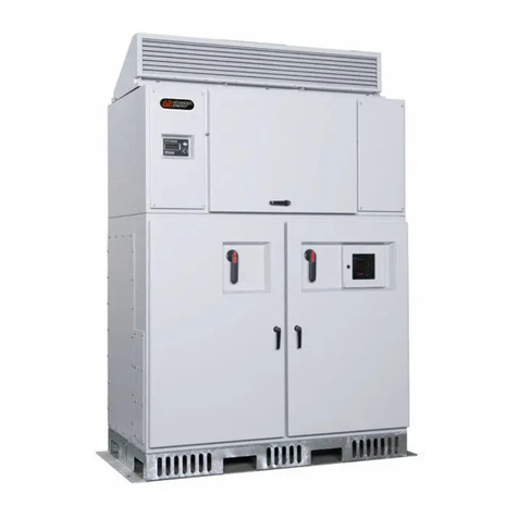
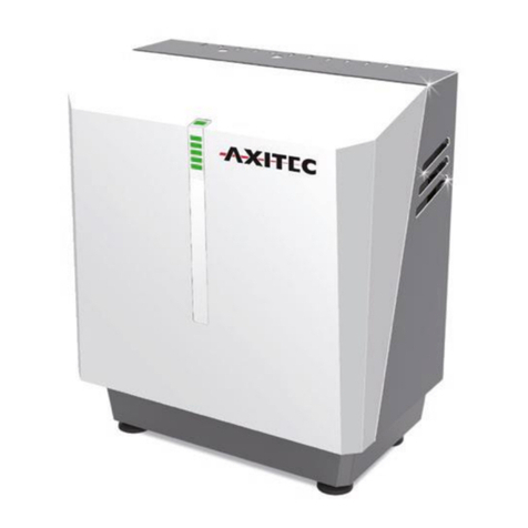
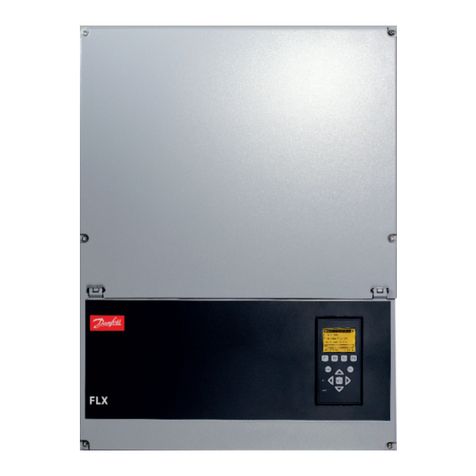
Advanced Energy AE 600 User manual

Advanced Energy® AE 500 Inverter
Installation and Operation
User Manual
March 2012 570-1001791-05A


Advanced Energy® AE 500 Inverter
Installation and Operation
User Manual
March 2012 570-1001791-05A

COPYRIGHT
This manual and the information contained herein are the proprietary property of Advanced
Energy Industries, Inc.
No part of this manual may be reproduced or copied without the express written permission of
Advanced Energy Industries, Inc. Any unauthorized use of this manual or its contents is
strictly prohibited. Copyright © 2012 Advanced Energy Industries, Inc. All Rights Reserved.
DISCLAIMER AND LIMITATION OF LIABILITY
The information contained in this manual is subject to change by Advanced Energy
Industries, Inc. without prior notice. Advanced Energy Industries, Inc. makes no warranty of
any kind whatsoever, either expressed or implied, with respect to the information contained
herein. Advanced Energy Industries, Inc. shall not be liable in damages, of whatever kind, as
a result of the reliance on or use of the information contained herein.
PRODUCT USAGE STATEMENT
WARNING :
Read this entire manual and all other publications pertaining to the work to
be performed before you install, operate, or maintain this equipment. Practice
all plant and product safety instructions and precautions. Failure to follow
instructions can cause personal injury and/or property damage. If the
equipment is used in a manner not specified by the manufacturer, the
protection provided by the equipment may be impaired. All personnel who
work with or who are exposed to this equipment must take precautions to
protect themselves against serious or possibly fatal bodily injury.
Advanced Energy Industries, Inc., (AE) provides information on its products
and associated hazards, but it assumes no responsibility for the after-sale
operation of the equipment or the safety practices of the owner or user.
NEVER DEFEAT INTERLOCKS OR GROUNDS.
Any use of the AE 500 unit that is not expressly authorized in this user
manual or associated documentation, including, without limitation, the use of
the AE 500 unit with incompatible photovoltaic panel technology, is expressly
prohibited by AE, and AE disclaims any responsibility or liability for such
prohibited use. The AE 500 unit should only be handled, installed, operated,
and maintained by trained personnel.
Advanced Energy
iv 570-1001791-05A

AVERTISSEMENT :
Lire ce manuel au complet ainsi que toutes les autres publications portant
sur le travail à effectuer avant d’installer, d’utiliser ou d’entretenir cet
équipement. Pratiquer toutes les instructions et précautions de sécurité pour
l’usine et les produits. Tout manquement aux instructions suivantes peut
provoquer des blessures corporelles et/ou des dommages matériels. Si
l’équipement est utilisé de manière non spécifiée par le fabricant, la
protection fournie par l’équipement peut être compromise. Tous les membres
du personnel travaillant sur cet équipement ou qui y sont exposés doivent
observer les précautions pour se protéger contre des blessures graves, voire
mortelles.
Advanced Energy Industries, Inc. (AE) fournit des renseignements sur ses
produits et les dangers qui y sont liés, mais ne peut être tenue responsable
du fonctionnement après-vente de l’équipement ou des pratiques de sécurité
du propriétaire ou de l’utilisateur. NE JAMAIS DÉJOUER LES DISPOSITIFS
DE PROTECTION À VERROUILLAGE OU LES MISES À LA TERRE.
Toute utilisation de cette unité AE 500 qui n’est pas expressément autorisée
dans ce guide de l’utilisateur ou dans la documentation connexe, y compris,
sans s'y limiter, l’utilisation de l’unité AE 500 avec des technologies de
panneaux photovoltaïques incompatibles, est expressément interdite par AE,
et AE décline toute responsabilité découlant d’un tel usage interdit. L'unité
AE 500 doit seulement être manipulée, installée, utilisée et entretenue par un
personnel formé.
TRADEMARKS
is a registered trademark of Advanced Energy Industries, Inc.
PVPowered™ is a trademark of Advanced Energy Industries, Inc.
Power Factor Pro™ is a trademark of Advanced Energy Industries, Inc.
Advanced Power Controls™ is a trademark of Advanced Energy Industries, Inc.
Modbus® is a registered trademark of Gould, Inc.
Windows® is a registered trademark of the Microsoft Corporation.
CUSTOMER FEEDBACK
Advanced Energy’s technical writing staff has carefully developed this manual using
research-based document design principles. However, improvement is ongoing, and the
writing staff welcomes and appreciates customer feedback. Please send any comments on the
content, organization, or format of this user manual to:
Advanced Energy® AE 500 Inverter
570-1001791-05A v

Table of Contents
Chapter 1. Safety and Product Compliance Guidelines
Important Safety Instructions ................................................................................ 1-1
Save These Instructions ........................................................................................ 1-1
Danger, Warning, and Caution Boxes in the Manual ............................................ 1-1
Safety Guidelines .................................................................................................. 1-2
Rules for Safe Installation and Operation ....................................................... 1-2
Personal Safety ..................................................................................................... 1-3
Medical and First Aid Treatment ..................................................................... 1-3
Safety Equipment Requirements .................................................................... 1-3
Interpreting Product Labels ................................................................................... 1-3
Product Compliance .............................................................................................. 1-4
Safety and EMC Directives and Standards .................................................... 1-5
Safety Directives and Standards .............................................................. 1-5
Electrical Safety .............................................................................................. 1-5
Disconnect Switch .................................................................................... 1-5
Wiring Requirements ...................................................................................... 1-6
Wiring Information .................................................................................... 1-6
Fire Prevention ............................................................................................... 1-8
Lockout and Tagout Requirements ....................................................................... 1-8
Acronyms and Frequently Used Terms ................................................................. 1-9
Chapter 2. Product Overview
General Description .............................................................................................. 2-1
Advanced Energy Inverter Models ................................................................. 2-1
Design Features ....................................................................................... 2-1
Product Features ................................................................................................... 2-2
Major Components and Functional Parts ............................................................. 2-3
Power Module Assembly ................................................................................ 2-4
Control Electronics ......................................................................................... 2-4
Data Monitoring Card Cage ............................................................................ 2-5
Communications Interface PCB ............................................................... 2-6
Operator Interface Controls ............................................................................ 2-6
Active Cooling System .................................................................................... 2-7
DC Combiner Sub Panel ................................................................................ 2-7
DC Sub Panel ................................................................................................. 2-7
AC Sub Panel ................................................................................................. 2-8
Housekeeping Transformer ............................................................................ 2-9
Magnetics Compartment ................................................................................ 2-9
Chapter 3. Planning
Advanced Energy® AE 500 Inverter
570-1001791-05A vii
Table of Contents

General Requirements for Planning and Installation ............................................. 3-1
Handling the Inverter ............................................................................................. 3-1
Handling Options ............................................................................................ 3-2
Storage .................................................................................................................. 3-2
Location and Clearances ...................................................................................... 3-2
Location .......................................................................................................... 3-2
Noise .............................................................................................................. 3-2
Recommended Clearances ............................................................................ 3-2
Conduit and Conductors ....................................................................................... 3-3
Environmental Requirements ................................................................................ 3-4
Grounding and Neutral Requirements .................................................................. 3-4
PV Array Frame Grounding ............................................................................ 3-4
System Neutral ............................................................................................... 3-5
Utility Grid Interconnection .................................................................................... 3-6
Utility Connection Requirements .................................................................... 3-6
Contacting Your Local Utility .......................................................................... 3-6
Voltage Output ................................................................................................ 3-6
Inverter Monitoring ................................................................................................ 3-6
Calculating DC Input Voltage ................................................................................ 3-7
DC Combiner Sub Panel Options ......................................................................... 3-7
Breaker Protection for DC Input ..................................................................... 3-8
Chapter 4. Installing
Handling and Unpacking ....................................................................................... 4-1
Packaging Contents ....................................................................................... 4-1
Handling and Unpacking the Inverter ............................................................. 4-1
Installing the Air Intake Hoods ........................................................................ 4-2
Pre-Installation Inspection ..................................................................................... 4-5
Pre-Installation Inspection Tools .................................................................... 4-5
Step 1: External Inspection ............................................................................. 4-6
Step 2: Inspection of Rear Magnetics ............................................................. 4-6
Step 3: AC and DC Sub Panel Compartments ............................................... 4-7
Step 4: Power Module Compartment ............................................................. 4-8
Step 5: Upper Active Cooling Compartment ................................................... 4-9
Lifting and Mounting the Inverter ......................................................................... 4-10
Conduit Entry Points ........................................................................................... 4-12
Using Gland Plates for Cable Conduit Entry and Exit .................................. 4-12
Electrical Connections ......................................................................................... 4-15
AC Wiring ..................................................................................................... 4-16
Connecting to the Electrical Grid ........................................................... 4-18
DC Wiring ..................................................................................................... 4-21
Connecting to the PV Arrays .................................................................. 4-22
Using the Integrated Remote Disable Input .................................................. 4-25
Making the Remote Disable Connection ................................................ 4-26
24 V Power Supply ....................................................................................... 4-28
Wiring the 24 V Power Supply ............................................................... 4-29
Advanced Energy
viii 570-1001791-05A
Table of Contents

Chapter 5. Operation
System Startup Procedure .................................................................................... 5-1
Inverter Operating States ...................................................................................... 5-2
Display Screens and Operation ............................................................................ 5-4
To Operate the Display ................................................................................... 5-6
Ground Fault Interrupt Device ............................................................................... 5-6
To Respond to a Ground Fault ....................................................................... 5-7
To Shutdown the Inverter ...................................................................................... 5-8
De-energize/Isolation Procedures .................................................................. 5-9
Inverter Enable/Disable Controls .................................................................. 5-10
Chapter 6. Data Monitoring and Controls
Networking and Performance Monitoring .............................................................. 6-1
Ethernet Network Connection ......................................................................... 6-1
Connecting the Ethernet Cable ...................................................................... 6-2
To Establish an Internet Connection with the Inverter .................................... 6-3
To Verify Data Monitoring Connectivity .......................................................... 6-4
Modbus Overview ................................................................................................. 6-4
Modbus Communication Protocol ................................................................... 6-4
Networking Using the Modbus Option ................................................................... 6-4
Modbus TCP Installation ................................................................................ 6-5
Modbus TCP Network Configuration .............................................................. 6-6
Networking Using the Modbus RS-485 Option ..................................................... 6-6
Network Layout ............................................................................................... 6-7
Installing the Modbus RS-485 Cable .............................................................. 6-8
Setting the DIP Switches ................................................................................ 6-9
To Terminate the Inverter Network ........................................................ 6-10
To Set the Center Inverters for the Network .......................................... 6-11
To Set Network Biasing ......................................................................... 6-11
To Terminate the Network and Enable Biasing ..................................... 6-11
Setting the Modbus Address ........................................................................ 6-11
Modbus Commands ............................................................................................ 6-16
Modbus Command Format ........................................................................... 6-16
Return Slave ID ............................................................................................ 6-18
Modbus Data Types ............................................................................................ 6-19
Modbus Register Mapping ................................................................................. 6-19
Modbus Fixed Information Registers ............................................................ 6-19
Modbus Data Registers ................................................................................ 6-22
Modbus Status and Fault Code Registers .................................................... 6-23
Modbus Command Registers ....................................................................... 6-26
Chapter 7. Maintenance
Advanced Energy® AE 500 Inverter
570-1001791-05A ix
Table of Contents

Visual Inspection ................................................................................................... 7-2
Maintenance Schedule .......................................................................................... 7-2
Replacement Parts ................................................................................................ 7-3
Checking and Replacing the Air Filters ................................................................. 7-4
Maintaining the Air Filters ............................................................................... 7-4
Maintaining the Card Cage Air Filter .............................................................. 7-6
Replacing the Battery on the Communications PCB ............................................. 7-6
Chapter 8. Troubleshooting and Solar Energy Technical
Support
Troubleshooting LAN Connectivity ........................................................................ 8-1
To Test the LAN Cable ................................................................................... 8-2
Troubleshooting Warnings and Faults .................................................................. 8-2
Troubleshooting Warnings .............................................................................. 8-3
System Warnings ..................................................................................... 8-3
Troubleshooting Inverter Faults ...................................................................... 8-4
AC Under Voltage Fault ........................................................................... 8-5
Ground Faults .......................................................................................... 8-5
To Resolve a Ground Fault ...................................................................... 8-6
Inverter Fault Codes ................................................................................ 8-8
PCB Status LEDs ................................................................................................ 8-13
Controller PCB Status LEDs ......................................................................... 8-13
Communication PCB Status LEDs ............................................................... 8-14
AE Solar Energy Technical Support .................................................................... 8-18
Appendix A. Specifications
Physical Specifications ......................................................................................... A-1
Electrical Specifications ....................................................................................... A-1
Efficiency Specifications ................................................................................ A-4
Efficiency Curves for the PVP500kW (480 VAC) Model ......................... A-4
Cooling Specifications .......................................................................................... A-4
Environmental Specifications ............................................................................... A-5
Appendix B. System and Mechanical Diagrams
System Diagram ................................................................................................... B-1
Mechanical Diagrams ........................................................................................... B-2
Advanced Energy
x 570-1001791-05A
Table of Contents

List of Tables
Table 1-1. Branch breaker size recommendations ............................................... 1-6
Table 1-2. Acronyms and frequently used terms .................................................. 1-9
Table 3-1. Inverter clearances .............................................................................. 3-2
Table 3-2. Cooling and heat rejection rate requirements ...................................... 3-4
Table 4-1. Subcombiner wire sizing and torque values ...................................... 4-16
Table 4-2. Branch breaker size recommendations ............................................. 4-17
Table 4-3. Operational voltage ranges per electrical panel ................................. 4-18
Table 5-1. Inverter enable/disable ....................................................................... 5-10
Table 6-1. Maximum network length per Modbus bit rate ................................... 6-10
Table 6-2. Inverter address table ........................................................................ 6-13
Table 6-3. Modbus commands ............................................................................ 6-16
Table 6-4. Format for Read Holding Register command ................................... 6-16
Table 6-5. Response format for Read Holding Register command .................... 6-17
Table 6-6. Format for Write Single Register command ....................................... 6-17
Table 6-7. Response format for Write Single Register command ....................... 6-17
Table 6-8. Format for Return Slave ID ................................................................ 6-18
Table 6-9. Format for Return Slave ID command ............................................... 6-18
Table 6-10. Data types ........................................................................................ 6-19
Table 6-11. Modbus fixed information registers .................................................. 6-20
Table 6-12. Inverter model number ..................................................................... 6-21
Table 6-13. Bit mapping for inverter configuration register ................................. 6-21
Table 6-14. Modbus data registers ..................................................................... 6-22
Table 6-15. Modbus status and fault code registers ........................................... 6-23
Table 6-16. Modbus inverter operating status register values ............................ 6-24
Table 6-17. PVM status register status code values ........................................... 6-25
Table 6-18. Modbus command registers ............................................................. 6-26
Table 7-1. Maintenance checklist .......................................................................... 7-3
Table 7-2. Inverter replacement parts ................................................................... 7-4
Table 8-1. Inverter system warnings ..................................................................... 8-4
Table 8-2. Fault categories ................................................................................... 8-8
Table 8-3. Drive (DRV) faults ................................................................................ 8-9
Table 8-4. Voltage (VLT) faults ........................................................................... 8-10
Table 8-5. Grid (GRD) faults ............................................................................... 8-11
Table 8-6. Temperature (TMP) faults .................................................................. 8-12
Table 8-7. System (SYS) faults ........................................................................... 8-12
Table 8-8. Controller PCB LEDs ......................................................................... 8-13
Table 8-9. Link LED ............................................................................................ 8-15
Table 8-10. Activity LED ...................................................................................... 8-15
Table 8-11. Status LED ....................................................................................... 8-16
Table 8-12. Modbus LED .................................................................................... 8-17
Table 8-13. AE Solar Energy Technical Support 24 X 7 contact information ...... 8-18
Table A-1. Physical specifications ........................................................................ A-1
Table A-2. Electrical specifications ...................................................................... A-2
Table A-3. Utility interconnect voltage and frequency trip limits and times .......... A-3
Table A-4. Efficiency specifications for the PVP500kW (480 VAC) model .......... A-4
Advanced Energy® AE 500 Inverter
570-1001791-05A xi
List of Tables

List of Figures
Figure 2-1. Components of the AE 500 inverter .................................................... 2-3
Figure 2-2. Power module assembly ..................................................................... 2-4
Figure 2-3. Control electronics compartment ........................................................ 2-5
Figure 2-4. Data monitoring card cage assembly ................................................. 2-6
Figure 2-5. DC combiner sub panel ...................................................................... 2-7
Figure 2-6. DC sub panel ...................................................................................... 2-8
Figure 2-7. AC sub panel ...................................................................................... 2-8
Figure 3-1. Inverter clearances ............................................................................. 3-3
Figure 3-2. DC subcombiner options .................................................................... 3-8
Figure 4-1. Stacked air intake hoods ................................................................... 4-3
Figure 4-2. Placing the air intake hood on the inverter ......................................... 4-4
Figure 4-3. Hinge on the air intake hood - locked and open positions .................. 4-4
Figure 4-4. Attaching the hood's gas springs to the inverter ................................. 4-5
Figure 4-5. Inductor and transformer connections ................................................ 4-6
Figure 4-6. Bus bar connection inspection ............................................................ 4-7
Figure 4-7. Pull test of cable screw terminal connection ....................................... 4-8
Figure 4-8. Screen inspection ............................................................................... 4-8
Figure 4-9. Check the bus bar connections .......................................................... 4-9
Figure 4-10. Fan inspection .................................................................................. 4-9
Figure 4-11. Air filter check ................................................................................. 4-10
Figure 4-12. DC bottom entry gland plates ......................................................... 4-13
Figure 4-13. DC side entry gland plates .............................................................. 4-14
Figure 4-14. Installation of conduit hub ............................................................... 4-14
Figure 4-15. AC connections ............................................................................... 4-20
Figure 4-16. Bus bar connections ....................................................................... 4-20
Figure 4-17. DC connections .............................................................................. 4-22
Figure 4-18. DC subcombiner configurations ...................................................... 4-23
Figure 4-19. DC dead front ................................................................................. 4-24
Figure 4-20. DC inverter connections ................................................................. 4-25
Figure 4-21. Remote disable wiring diagram ...................................................... 4-27
Figure 4-22. Remote disable terminal block ........................................................ 4-28
Figure 4-23. 24 V power supply terminal location ............................................... 4-29
Figure 4-24. 24 V wiring example ....................................................................... 4-30
Figure 5-1. Inverter with AC disconnect power ON ............................................... 5-2
Figure 5-2. Inverter state diagram ......................................................................... 5-3
Figure 5-3. Initialize state screen .......................................................................... 5-5
Figure 5-4. Energy tracking state screens ............................................................ 5-5
Figure 5-5. Fault state screens ............................................................................. 5-5
Figure 5-6. Warning state screen .......................................................................... 5-6
Figure 5-7. Disabled state screen ......................................................................... 5-6
Figure 5-8. Inverter display and switch ................................................................. 5-6
Figure 5-9. Ground fault error message ................................................................ 5-7
Figure 5-10. AC disconnect power OFF ................................................................ 5-8
Figure 6-1. T-568B compliant Ethernet cable ....................................................... 6-2
Figure 6-2. Communication interface PCB Ethernet port location ........................ 6-3
Advanced Energy® AE 500 Inverter
570-1001791-05A xiii
List of Figures

Figure 6-3. Communication interface PCB in the data monitoring section ............ 6-6
Figure 6-4. Daisy chain layout for RS-485 network: option A ............................... 6-7
Figure 6-5. Daisy chain layout for RS-485 network: option B ............................... 6-7
Figure 6-6. Daisy chain layout for RS-485 network: option C ............................... 6-7
Figure 6-7. Communications interface PCB with Modbus slave port location ....... 6-9
Figure 6-8. Termination switches on the user interface PCB .............................. 6-10
Figure 6-9. Setting the Modbus address ............................................................. 6-12
Figure 6-10. Example: Unit address switch set to address 25 ............................ 6-13
Figure 7-1. Air intake hoods .................................................................................. 7-5
Figure 7-2. Air intake hood in raised position ........................................................ 7-5
Figure 7-3. Card cage air filter .............................................................................. 7-6
Figure 8-1. Warning screen ................................................................................... 8-3
Figure 8-2. Screen sequence when an inverter faults ........................................... 8-5
Figure 8-3. Communication PCB with status LEDs ............................................. 8-14
Figure 8-4. Communication interface PCB with LEDs ........................................ 8-15
Figure A-1. Efficiency curves for the PVP500kW (480 VAC) model .................... A-4
Figure B-1. AE 500 system diagram .................................................................... B-1
Figure B-2. AE 500 mechanical diagram: View 1 ................................................. B-2
Figure B-3. AE 500 mechanical diagram: View 2 ................................................. B-3
Figure B-4. AE 500 mechanical diagram: View 3 ................................................. B-4
Advanced Energy
xiv 570-1001791-05A
List of Figures

Safety and Product Compliance
Guidelines
IMPORTANT SAFETY INSTRUCTIONS
To ensure safe installation and operation of the Advanced Energy AE 500 unit, read
and understand this manual before attempting to install and operate this inverter. At a
minimum, read and follow the safety guidelines, instructions, and practices.
SAVE THESE INSTRUCTIONS
This manual contains important instructions for the AE 500 unit that shall be
followed during installation and maintenance of the unit.
DANGER, WARNING, AND CAUTION BOXES
IN THE MANUAL
This symbol represents important notes concerning potential harm to people, this
unit, or associated equipment. Advanced Energy includes this symbol in Danger,
Warning, and Caution boxes to identify specific levels of hazard seriousness.
DANGER:
DANGER indicates an imminently hazardous situation that, if not avoided,
will result in death or serious injury. DANGER is limited to the most extreme
situations.
DANGER:
DANGER indique une situation dangereuse imminente qui, si elle n’est pas
évitée, pourrait provoquer la mort ou des blessures graves. DANGER est
réservé aux situations les plus extrêmes.
Advanced Energy® AE 500 Inverter Chapter
1
1027
570-1001791-05A Safety and Product Compliance Guidelines 1‑1

WARNING:
WARNING indicates a potentially hazardous situation that, if not avoided,
could result in death or serious injury, and/or property damage.
AVERTISSEMENT:
AVERTISSEMENT indique une situation potentiellement dangereuse qui, si
elle n’est pas évitée, pourrait provoquer la mort ou des blessures graves et/
ou des dommages matériels.
CAUTION:
CAUTION indicates a potentially hazardous situation that, if not avoided,
could result in minor or moderate injury, and/or property damage. CAUTION
is also used for property-damage-only accidents.
ATTENTION:
ATTENTION indique une situation potentiellement dangereuse qui, si elle
n’est pas évitée, pourrait provoquer des blessures mineures ou modérées et/
ou des dommages matériels. ATTENTION est également utilisé pour des
accidents causant uniquement des dommages matériels.
SAFETY GUIDELINES
Review the following information before attempting to install and operate the
product.
Rules for Safe Installation and Operation
Please note the following rules:
•Do not attempt to install or operate this equipment without proper training.
• Ensure that this unit is properly grounded.
• Ensure that all cables are properly connected.
• Verify that input line voltage and current capacity are within specifications
before turning on the power supplies.
• Use proper electrostatic discharge (ESD) precautions.
• Always be careful around this equipment.
Advanced Energy
1‑2 Safety and Product Compliance Guidelines 570-1001791-05A

PERSONAL SAFETY
Ensure any personnel entering a safety zone within a four foot area around any
operating inverter wear appropriate Personal Protective Equipment (PPE) as
mandated by national, state, and local authorities.
Medical and First Aid Treatment
Personnel working in and around operating power generation equipment should be
trained in Arc Flash Hazard, Fire Extinguisher selection and use, First Aid, Cardio
Pulmonary Resuscitation (CPR), and Automated External Defibrillator (AED) use (if
available).
Safety Equipment Requirements
Authorized service personnel performing operations on this unit should have the
following minimum safety equipment available:
•Consult NFPA 70E, or applicable local standards, for PPE requirements on
switch gear operating at less than 600 V
• Electrical hazard footwear (ANSI Z41/Z85 rated)
• Lock Out Tag Out (LOTO) Kit
• Appropriate meter to verify the circuits are safely de-energized (1000 VAC and
DC rated, minimum)
• Any other equipment as applicable to your operation as required by national,
state, and local regulations
INTERPRETING PRODUCT LABELS
The following labels may appear on your unit:
Earth ground
Advanced Energy® AE 500 Inverter
570-1001791-05A Safety and Product Compliance Guidelines 1‑3

Chassis ground
4588
On or off
4589
or
4590
Phase
1025
Electrical fuse
1026
Alternating current
4205
Direct current
Positive ground
Negative ground
PRODUCT COMPLIANCE
The following sections include information about unit compliance and certification,
including the conditions of use required to be in compliance with the standards and
directives.
Advanced Energy
1‑4 Safety and Product Compliance Guidelines 570-1001791-05A

Safety and EMC Directives and Standards
Certain options of this unit have been tested for and comply with the following
electromagnetic compatibility (EMC) and safety directives and standards and
industry guidelines.
☞ Important
This equipment must be installed and used in accordance with the Conditions
of Use described in this manual. If this equipment is expanded, modified, or
installed into a larger system, the user is responsible to guarantee the
compliance of the overall system. If this equipment is used with external
components, the user must ensure that the Safety and EMC requirements are
not violated.
SAFETY DIRECTIVES AND STANDARDS
•UL1741
Inverters, Converters, Controllers and Interconnection System Equipment for
Use With Distributed Energy Resources (2010)
◦IEEE 1547
Standard for Interconnecting Distributed Resource with Electric Power
Systems
◦IEEE 1547.1
Standard for Conformance Tests Procedures for Equipment Interconnecting
Distributed Resources with Electric Power Systems
•FCC Part 15 Class A conducted emissions
•CSA C22.2 No. 107.1-01
General use power supplies—industrial products
•National Electrical Code
Can be installed in compliance with National Electrical Code 2008 and 2011
Editions Article 690 Solar Photovoltaic Systems
Electrical Safety
DISCONNECT SWITCH
The inverter is equipped with an AC disconnect (power OFF) to stop power
conversion within the inverter. Before accessing the interior of the cabinet, this
disconnect must be in the OFF position. Since this disconnect only stops power
conversion within the inverter, both the external (or optional inverter integrated) DC
(photovoltaic array) and AC (utility grid) circuits must be isolated in order to fully
ensure the inverter is de-energized. Wait five minutes for the inverter to de-energize
before working on the inverter.
Advanced Energy® AE 500 Inverter
570-1001791-05A Safety and Product Compliance Guidelines 1‑5

AC/DC DISCONNECT DEVICE AND OTHER REQUIREMENTS
If the optional inverter integrated AC disconnect and inverter integrated DC
subcombiner breakers were not selected, then isolated disconnect devices must be
provided for both the PV array DC connection and for the AC utility grid connection
when installing an AE inverter.
AC DISCONNECT DEVICE, OVERCURRENT PROTECTION,
AND TRANSFORMER REQUIREMENTS
If the optional inverter integrated AC disconnect was not selected, then you must
install an AC disconnect and overcurrent protection device at the AE inverter that
complies with National Electric Code ANSI/NFPA 70 and local building code
requirements, whichever is more restrictive. The AC disconnect must be rated for
480 VAC at the maximum overcurrent protection setting, typically 1.25 * IAC
maximum. You must connect the inverter to a three-phase 480 VAC grounded wye
feeder or an 800 A service. Refer to the table below.
DC DISCONNECT DEVICE AND FUSE REQUIREMENTS
If the optional DC subcombiner circuit breakers were not selected, then you must
provide a DC disconnect and fusing for each section (or sub-array) of the PV array.
The disconnect must be rated for the voltage and the current rating of the
photovoltaic array connected to the inverter. The DC disconnect installation must
comply with your national and local electrical code.
Wiring Requirements
You must meet the following requirements when wiring the AE 500 inverter:
Table 1‑1. Branch breaker size recommendations
Model 208 VAC 480 VAC 600 VAC
AE 500 N/A 800 A N/A
WIRING INFORMATION
☞ Important
You must use National Electrical Code (ANSI/NFPA 70) wiring methods.
DANGER:
Do not connect the PV negative or positive conductors to the ground bus
bars provided. The PV array is grounded through the integral GFDI.
Connecting the PV array positive or negative conductors to ground at any
other point in the system would defeat the ground fault protection circuit.
Advanced Energy
1‑6 Safety and Product Compliance Guidelines 570-1001791-05A
This manual suits for next models
1
Table of contents
Other Advanced Energy Inverter manuals
Popular Inverter manuals by other brands
Sinexcel
Sinexcel PWS2-30M-EX user manual
Hitachi
Hitachi P1-00080-L Basic guide
Hitachi
Hitachi S1 Series Basic guide

Mitsubishi Electric
Mitsubishi Electric FR-D700 Series Safety stop function instruction manual

Champion
Champion 73001i-DF (EU) Owner's manual & operating instructions

Endress
Endress ESE 608 DHG ES DI DUPLEX operating instructions


