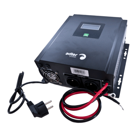
Advantech-DLoG DLT-U1100 User manual

1
Mounting by electronic and mechanical skilled persons
Quickstart
DLT-U1100
2
Important notes
Personal injury
Explosion hazard
The following icons are used in this quick start guide to indicate dangers:
NOTICE Risk of physical damage
3
Technical data
Battery Lithium-ion battery
Bridging time 10 min
Maximum output 40 W
Nominal output voltage of the UPS 12 VDC
Nominal input voltage of the UPS 12, 24, 48 VDC
Input voltage range 9 to 60 VDC
Output voltage range 10 to 14 VDC
Charging time 2,5 h (fully recharge a completely discharged battery)
Connector input Lumberg 0315 04-Pin male
Connector output Lumberg 0305 04-Pin female
Qualications required for mounting of the UPS DLT-U1100
This Quickstart Poster will show you how to perform the mechanical and electrical mounting
of the Uninterruptible Power Supply (UPS) DLT-U1100. It is intended for skilled persons.
WARNING: Electric shock due to contact with live parts / property damage
• Only electronic and mechanical skilled persons are permitted to install the
DLT-U1100. Specialized knowledge of batteries and the applicable safety
regulations is also required.
• Unauthorized persons must be kept away from the UPS which contains
rechargeable Lithium Ion batteries.
• IftheDLT-U1100isincorrectlyinstalledandcongured,theDLoGGmbHwarranty
for this device will be canceled.
• DLoGGmbHassumesnoliabilityfordamagescauseddirectlyorindirectly
by the incorrect installation or usage of the DLT-U1100.
• DLT-U1100 operators must be trained.
Current manuals on the internet
The current DLT-U1100 manuals can always be found in our Download Center
on the internet www.advantech-dlog.com (Download menu).
Intended use
TheDLT-U1100isabattery-operateduninterruptiblepowersupplyfortheAdvantech-DLoG
industrial PCs MTC 6 and XMT 5, each with 12/24 VDC power supply unit.
If the DLT-U1100 is connected, MTC 6 and XMT 5 cannot be started or shut down automati-
cally via vehicle ignition.
NOTICE: No combination of UPS + automatic start/shut down via ignition
possible
MTC 6 and XMT 5 can be used with automatic startup/shut down capabilities.
This automatic feature controls the startup and shutdown of the industrial PC
via the <POWER> button or the vehicle’s ignition.
If the DLT-U1100 is connected, MTC 6 and XMT 5 cannot be started or shut down via
vehicle ignition
Henceitisimportanttomakethefollowingsettingbefore the DLT-U1100 is connected
to MTC 6 and XMT 5:
• DenethattheMTC6andXMT5alwaysstartandshutdownwiththe
<POWER> button, not via ignition signal.
• Maketherespectiveadjustmentsinthecongurationtools:
“DLoGCong“forMTC6,“DLoGNextCong“forXMT5
Otherwise, MTC 6 and XMT 5 can not be started, because with a connected UPS
system no ignition signal is available.
WARNING: Vehicle “EMERGENCY Stop Switch” cannot switch off industrial
PCs with UPS
If an MTC 6 or XMT 5 industrial PC with an uninterruptible power supply (UPS) is
installed on a vehicle, the vehicle emergency stop switch will not affect the the
industrial PC.
WARNING: Explosion hazard
• DonotusetheDLT-U1100atlocationswhereammablegasesorvaporsare
present.
• Do not use the DLT-U1100 near gas stations, fuel depots, chemical facilities or
locations where blasting work is being performed.
• DonotthrowtheDLT-U1100intore;thebatteriesmayexplode.
WARNING: Electrical shock possible from touching live parts / property damage
• Do not commission the DLT-U1100 if there are visible signs of damage to the
device.
• The DLT-U1100 contains Lithium Ion batteries. Replacement of the rechargeable
batteries by the customer is expressly prohibited.
• Do not open or modify the DLT-U1100.
• Do not perform any repairs. Repairs on the DLT-U1100 may be made only by
ServiceCentersauthorizedbyAdvantech-DLoG.
• Do not submerge the DLT-U1100 and cables in water or other liquids because of
the danger of electrical shock.
• UseonlyoriginalpowercablesbyAdvantech-DLoG;theymeetspecial
requirementsforlow-temperatureexibility,UVresistance,oilresistance,etc.
• Condensation can occur if the DLT-U1100 is moved from a cold environment into
a work room. Therefore, allow for an acclimatization time of approx. 2 hours.
Temperature range, in which the UPS supplies
the industrial PC with power from the battery
-10 to +50 °C (+14 to +122 °F)
Temperature range, in which the batteries
of the UPS are recharged
0 to +45 °C (+32 to +113 °F)
Storage temperature range -20 to +60 °C (-4 to +140 °F)
Vibration/shock Class 5M3 according to DIN EN 60721-3-5
IP protection IP65
Weight 1.1 kg
Warranty DLT-U1100 device (batteries
excluded)
AsspeciedinAdvantech-DLoGTOB
Warranty batteries Six (6) months from delivery
Any other or additional use is not as intended.
The user/operator of the DLT-U1100 is solely respon-
sible for any resulting damage. This also applies to
unauthorizedmodicationstotheunit.

4
Mounting position on the vehicle
6
Mechanical and electrical mounting
Electrical connection points on the vehicle
The electrical connection point suitable for the DLT-U1100 depends on the respective
vehicle type.
• Make sure to observe the technical/electrical information of the vehicle manufacturer.
• Keep in mind that certain electrical connection points are not suitable for the
DLT-U1100, e.g. for vehicles with braking energy reclamation.
• Position the DLT-U1100 as closely as possible to the connection point and
connect it there.
• Make sure that the connection point exhibits a stable potential level.
• Do not connect the DLT-U1100 directly to the circuit of high power consumption
devices(e.g.convertersforforkliftdrives);thismayresultinsuddenrestarts,
malfunctions or damage to the device.
• With some vehicles, the chassis represents DC+. The DLT-U1100 chassis is then also
DC+. If peripheral devices now supply DC-, e.g. via a plug connector through a serial
interface to the shield connection of the DLT-U1100, a short circuit is inevitable and
malfunctions/total failures are unavoidable.
• It must be ensured with these vehicles that the UPS case does not have any electrical
connection to the vehicle body.
5
Electrical connection data
7
Contact
Advantech-DLoG [email protected]
Industriestraße 15 www.advantech-dlog.com
D-82110Germering Telefon:(+49)89/411191-999
QuickstartGuideDLT-U1100V1.00DAN885196E01/30/2014
Copyright2014byDLoGGmbH,Industriestraße15,D-82110Germering
All rights reserved. Information in this document is subject to change without prior notice.
DLT-U1100 dimensions (in mm)
Mounting steps
• Mount the DLT-U1100 1on the vehicle via the two mounting brackets
and four M3.5x6 mm threaded screws.
• Connect the connection cable 2to the electrical connection point of the vehicle.
• Connect with the DLT-U1100 (input) as shown in position 6.
• Connect connection cable 3to the industrial PC.
• For this purpose, plug the Phoenix contact plug 4into the UPS connection of the
industrial PC and screw tight.
• Connect and fasten the ground cable to the ground pin of the industrial PC.
• Connect with the UPS (output) as shown in position 7.
• Fasten all cables securely.
1
2
3
4
5
67
Mounting brackets
with 2 drill holes
for M3.5x6 mm
threaded screws
Suitable mounting position
• Take the permissible working temperature range of the DLT-U1100 into account
(heat development of the vehicle, e.g. near the engine).
• TheUPSDLT-U1100heatsupduringthechargingprocess;forthisreason,makesure
to provide for adequate ventilation. Do not cover the UPS.
• Check the available cable length. Both the electronic connection point of the vehicle
and the industrial PC must be easily reached.
• Install the cables according to the regulations. Cables must not interfere with the ongoing
operation or present a hazard to persons.
• Screwthecablessufcientlytightbutmakesurenottopinchthem.Otherwise,thecable
may break or the cable insulation may be damaged.
• Observethespecicationsofthevehiclemanufacturerfortheattachmentofadditional
devices. Special attention must be paid to regulations about welding or drilling work
performed on structural parts.
• Observe the permissible ambient conditions of the DLT-U1100.
Power supply cable (detail view)
1DLT-U1100 case
2UPS connection cable <–> power source
on the vehicle
3UPS connection cable <–> industrial PC
4Phoenix contact plug and ground cable
for industrial PC
5Cables with wires for the power source
on the vehicle
6Direct current input from the power
source at the vehicle
7Direct current output to the industrial PC
Required components
Pins input / output
Popular UPS manuals by other brands
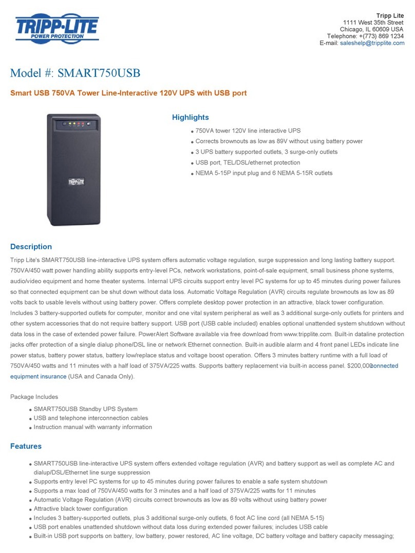
Tripp Lite
Tripp Lite Line-Interactive UPS System SMART750USB Specifications
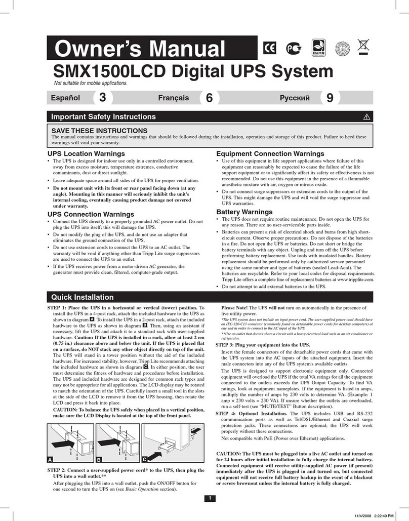
Tripp Lite
Tripp Lite SMX1500LCD owner's manual

Tripp Lite
Tripp Lite BC Internet owner's manual
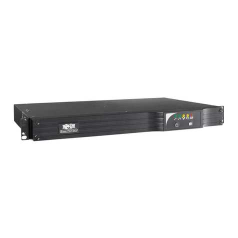
Tripp Lite
Tripp Lite SmartPro Rackmount SMX500RT1U owner's manual
Tripp Lite
Tripp Lite INTERNET550U specification
NGS
NGS FORTRESS user manual
