Advantech AMAX-3100 Series Instructions for use
AMAX-3100 Series
Hardware User Manual

I
Contents
1. Introduction ...........................................................................................................1
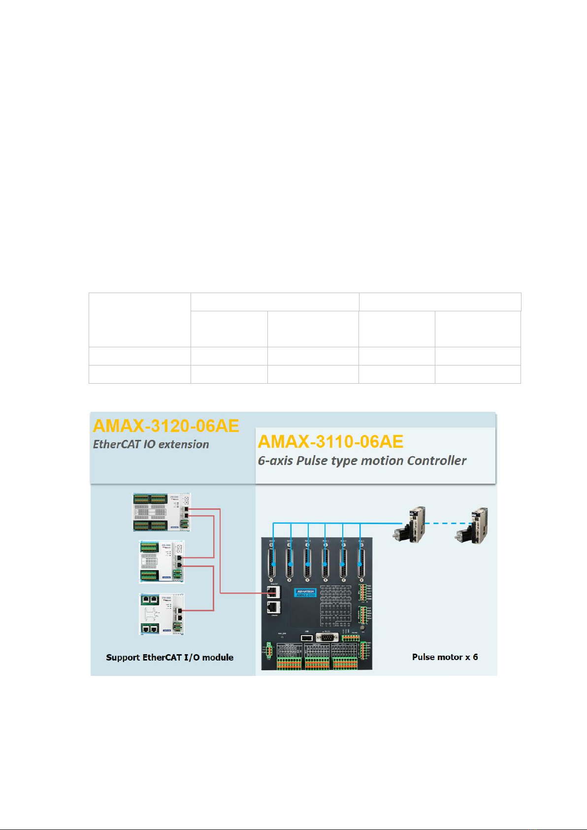
1.1 AMAX-3100 Series Controllers...............................................................2
1.2 AMAX-3100 Architecture .......................................................................3
1.3 AMAX-3100 Specification.......................................................................3
1.4 Accessory ...............................................................................................5
1.4.1 Mount Type....................................................................................5
1.4.2 Cable of Motor connecting ............................................................5
2. Hardware and Wiring.............................................................................................6
2.1 AMAX-3100 Front View..........................................................................7
2.2 CN1 (Power) ...........................................................................................8
2.2.1 CN1 Pin Definition..........................................................................8
2.2.2 CN1 Wiring....................................................................................8
2.3 CN2 & CN5 (Digital Output) ...................................................................9
2.3.1 CN2 (General Output) Pin Definition .............................................9
2.3.2 CN5 (EMG/CMP/LTC)....................................................................10
2.3.3 CN2 & CN5(DO) Wiring ................................................................10
2.4 CN3, CN4, CN5 (Digital Input) ..............................................................11
2.4.1 CN3(General Input) Pin Definition...............................................11
2.4.2 CN4 (Limit and Home) Pin Definition...........................................12
2.4.3 CN5 (EMG/CMP/LTC) Pin Definition.............................................13
2.4.4 CN3, CN4, CN5 Wiring..................................................................13
2.5 CN6 (MPG) Handweel ..........................................................................15
2.5.1 CN6 (MPG) Pin Definition ............................................................15
2.5.2 CN6 Wiring...................................................................................16
2.6 CN7 (PWM) ..........................................................................................17
2.6.1 CN7 (PWM) Pin Definition ...........................................................17
2.6.2 CN7 Wiring ...................................................................................18
2.7 Axis0-5 (DB-25) Motor Connecting......................................................19
2.7.1 Axis0-5 Pin Definition...................................................................19
2.7.2 Axis0-5 Wiring..............................................................................20
2.8 RS-485 ..................................................................................................22
2.9 RS-232 ..................................................................................................22
2.10 USB.......................................................................................................23
2.11 SW (Rotary Switch) .............................................................................23
2.11.1 Normal Mode...............................................................................23
2.11.2 FW Update Mode.........................................................................24
2.11.3 APP(file) Update Mode ................................................................24

II
AMAX-3100 Hardware Manual
2.11.3.1 Update ARES program..................................................24
2.11.3.2 Update Network Settings.............................................24
2.11.3.3 Reset to Factory Mode.................................................25
2.12 Ethernet ...............................................................................................26
2.13 EtherCAT...............................................................................................26
2.14 LED Indicator........................................................................................27
2.14.1 I/O LED Status ..............................................................................27
2.14.2 System LED Status........................................................................28
2.15 DI/DO Hardware Specification.............................................................29
2.15.1 DI0 ~ 15, RDY, ALM, INP (Low Speed DI)......................................29
2.15.2 LMT+, LMT-, ORG, EMG (High Speed DI)......................................30
2.15.3 LTC0, LTC1.....................................................................................30
2.15.4 DO 0 ~ 11, RST, ERC, SVON...........................................................31
2.15.5 CMP 0, CMP 1...............................................................................31
2.15.6 ENC_A0/1 +/-, ENC_B0/1 +/- .......................................................32
2.15.7 PWM0 +/-, PWM1 +/- ..................................................................32

1
AMAX-3100 Hardware Manual
1. Introduction
2
AMAX-3100 Hardware Manual
AMAX-3100 is designed for high speed and precise motion control with compact
size and integrates motion and I/O control. AMAX-3100 built-in ARM processor which
can support real-time control to enhance system efficiency and reliability. In terms of
software, AMAX-3100 built-in Advantech Softmotion kernel supports interpolation
and high precise trajectory, furthermore, AMAX-3100 provides ARES Developer IDE
supporting ARES script which is a G-code-like language to shorten the development
time and speed-up hands on.
AMAX-3100 controller Integrates the hardware and software to save our cost
and time, provides users a more cost-effective choice of motion control solution.
1.1 AMAX-3100 Series Controllers
Controller
Axes
I/O
Locak
(Pulse type)
Extension
(EtherCAT)
Local
Extension
(EtherCAT)
AMAX-3110-06AE
6
0
16DI / 12DO
0
AMAX-3120-06AE
6
0
16DI / 12DO
512 Bytes I/O
*Note:AMAX-3120-06AE hasn’t released.

3
AMAX-3100 Hardware Manual
1.2 AMAX-3100 Architecture
AMAX-3100 is an ARM-based solution and provides easy-to-use IDE ARES
Developer. Users can install ARES Developer which is designed for machine makers
on IPC or notebook and edit, compile, run the programs on ARES developer,
download the developed programs to AMAX-3100 via Ethernet. In addition, AMAX-
3100 also provides Modbus TCP/RTU to connect to 3rd party devices and HMI to
achieve the User Interface.
AMAX-3100 System
1.3 AMAX-3100 Specification
Item
AMAX-3110-06AE
System
CPU
Dual-core Cortex-A9 667MHz
RAM
DDR3L 512MB
Retain memory(FRAM)
FRAM 64Kb (8K Byte)
eMMC space
8GB
System IO
Ethernet
RJ-45 x 1 (10/100Mbps)
EtherCAT
Reserved
RS232/485
RS-232 x 1 (2400 - 115200bps)

4
AMAX-3100 Hardware Manual
RS-485 x 1(2400 - 115200bps)
USB
USB 2.0 x 1 (Host)
Motion
Pulse Output
6-Axis
CW/CCW, A/B, Pulse Direction Mode
5MHz
Output Voltage 3Vdc
Pulse Input
6Ch. (A,B,Z)
A/B phase, CW/CCW Mode
5MHz
Input Voltage 5V (Max.)
Range -2,147,483,647~+2,147,483,648 (32bits)
Hand Wheel
Input mode x4 A/B phase
250kHz
Input Voltage 5V (Max.)
Motion IO
Low Speed Digital Input
INP x 6, ALM x 6, RDY x 6
Input Voltage 24V(Max.)
Input delay: 1ms
High Speed Digital Input
EMG x 1, ORG x 6, LMT± x 6
Input Voltage 24V
Input delay: 100us (Max.)
Digital Output
SVON x 6, ERC x 6, RST x 6
Output Voltage Open Collector 24Vdc (Max.)
Sink Current 20mA/CH
Input delay: 1ms (Max.)
Latch In
2Ch.
Input Voltage 24V
100kHz
Compare Trigger
2Ch. (single-Ended)
Input Voltage 24V
Sink Current 500mA/CH
100kHz
PWM
(Differential Output)
2Ch.(Differential)
Output Voltage 3Vdc (Max.)
1MHz
General I/O
Digital Input
16 Ch.

5
AMAX-3100 Hardware Manual
Input Voltage 24V(Max.)
Input delay : 1ms
Digital Output
12 Ch.
Output Voltage Open Collector 24Vdc (Max.)
Leak Current < 10uA
Sink Current 500mA/CH
Input delay time 1ms
EtherCAT
Motion
x
I/O
x
General
LED
Power/ RUN/ ERROR/ UPD / IO Status
Rotary Switch
4bits x 1
Input Voltage
24VDC +/- 15%
Power Consumption
17W
Dimension (W x H x D)
150 x 180 x 21 mm
Certifications
CE, FCC Class A
Relative Humidity
5~95% RH non-condensing
Operation Temperature
0 to 60 degree C
Storage Temperature
-20 to 85 degree C
1.4 Accessory
1.4.1 Mount Type
AMAX-3100 provides two types of mount which are din-rail and wall-mount.
The default setting of shipping is wall-mount, users can also purchase a din-rail
mount kit which is 1950016395T101 Advantech part number according to their
needs.
1.4.2 Cable of Motor connecting
PCL-30153PA5
PCL-10153PA5 is a 50 Pin cable which is connected to Panasonic A4/A5 servo
driver.
PCL-30153YS5
PCL-30153YS5 is a 50 Pin cable which is connected to Yaskawa Sigma V servo

6
AMAX-3100 Hardware Manual
driver.
PCL-30153MJ3
PCL-30153YS5 is a 50 Pin cable which is connected to Mitsubish J3 servo driver.
PCL-30153DA2
PCL-30153YS5 is a 50 Pin cable which is connected to Delta A2 servo driver.
2. Hardware and Wiring
7
AMAX-3100 用戶手冊
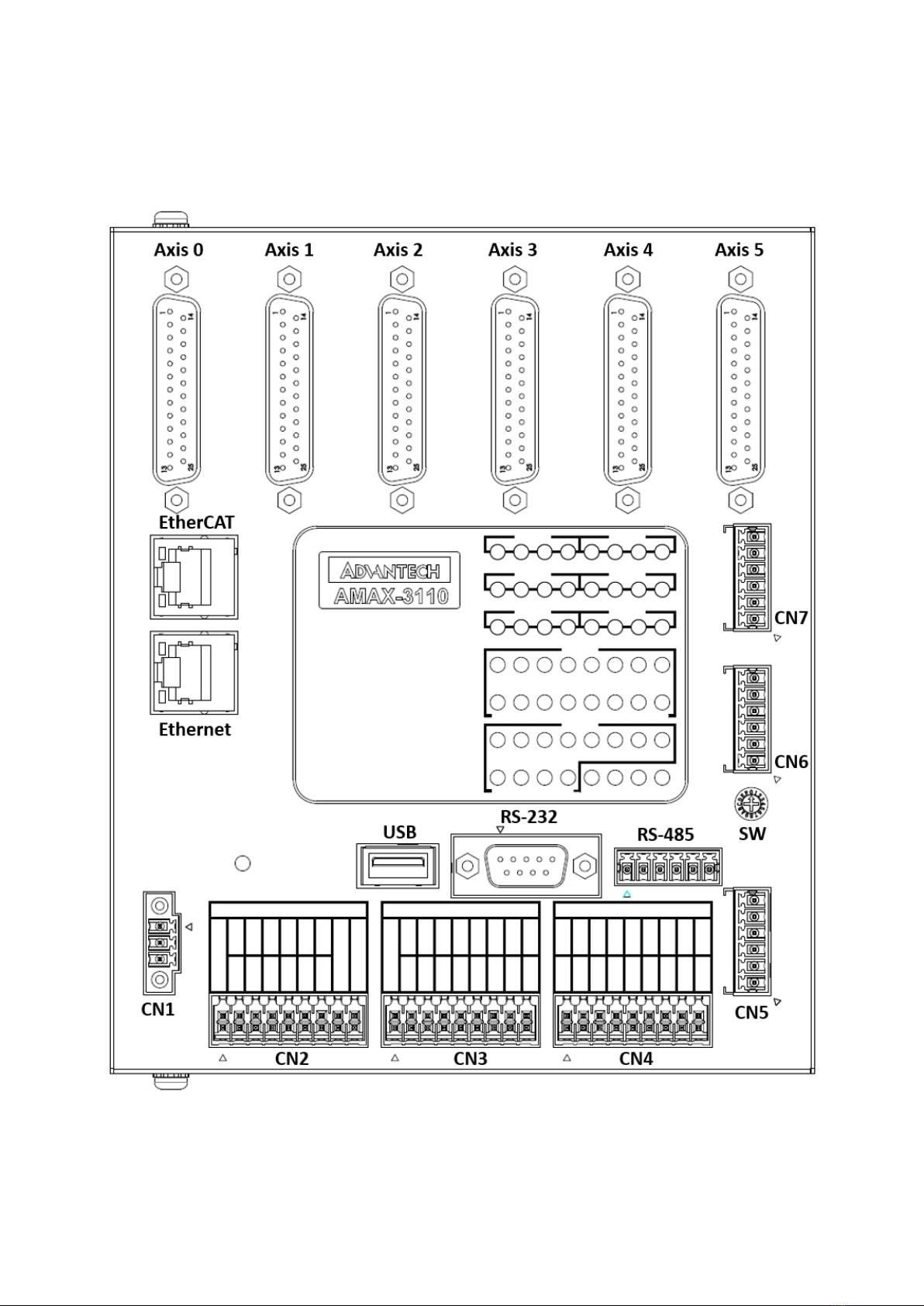
2.1 AMAX-3100 Front View

8
AMAX-3100 用戶手冊
2.2 CN1 (Power)
2.2.1 CN1 Pin Definition
Pin
Name
Description
1
VEX+
+24V Power Input
2
VEX-
Power Ground
3
FGND
Field Ground
2.2.2 CN1Wiring

9
AMAX-3100 用戶手冊
2.3 CN2 & CN5 (Digital Output)
2.3.1 CN2 (General Output) Pin Definition
Pin
Name
Description
1
FWCOM
Freewheeling Diode COM.
2
FWCOM
Freewheeling Diode COM.
3
OUT6
General Digital Output 6
4
OUT0
General Digital Output 0
5
OUT7
General Digital Output 7
6
OUT1
General Digital Output 1
7
OUT8
General Digital Output 8
8
OUT2
General Digital Output 2
9
OUT9
General Digital Output 9
10
OUT3
General Digital Output 3
11
OUT10
General Digital Output 10
12
OUT4
General Digital Output 4
13
OUT11
General Digital Output 11
14
OUT5
General Digital Output 5
15
GND
Digital Output Ground
16
GND
Digital Output Ground
17
NC
No Connection

10
AMAX-3100 用戶手冊
18
NC
No Connection
2.3.2 CN5 (EMG/CMP/LTC)
Pin
Name
Description
1
EMG
Emergency Stop Input
2
LTC0
Position Latch Input 0
3
LTC1
Position Latch Input 1
4
CMP0
Position Compare Output 0
5
CMP1
Position Compare Output 1
6
CGND
Compare Output Ground
2.3.3 CN2 & CN5(DO) Wiring
CN2 and CN5 has respective GND
CN2: Pin15, 16
CN5: Pin 6

11
AMAX-3100 用戶手冊
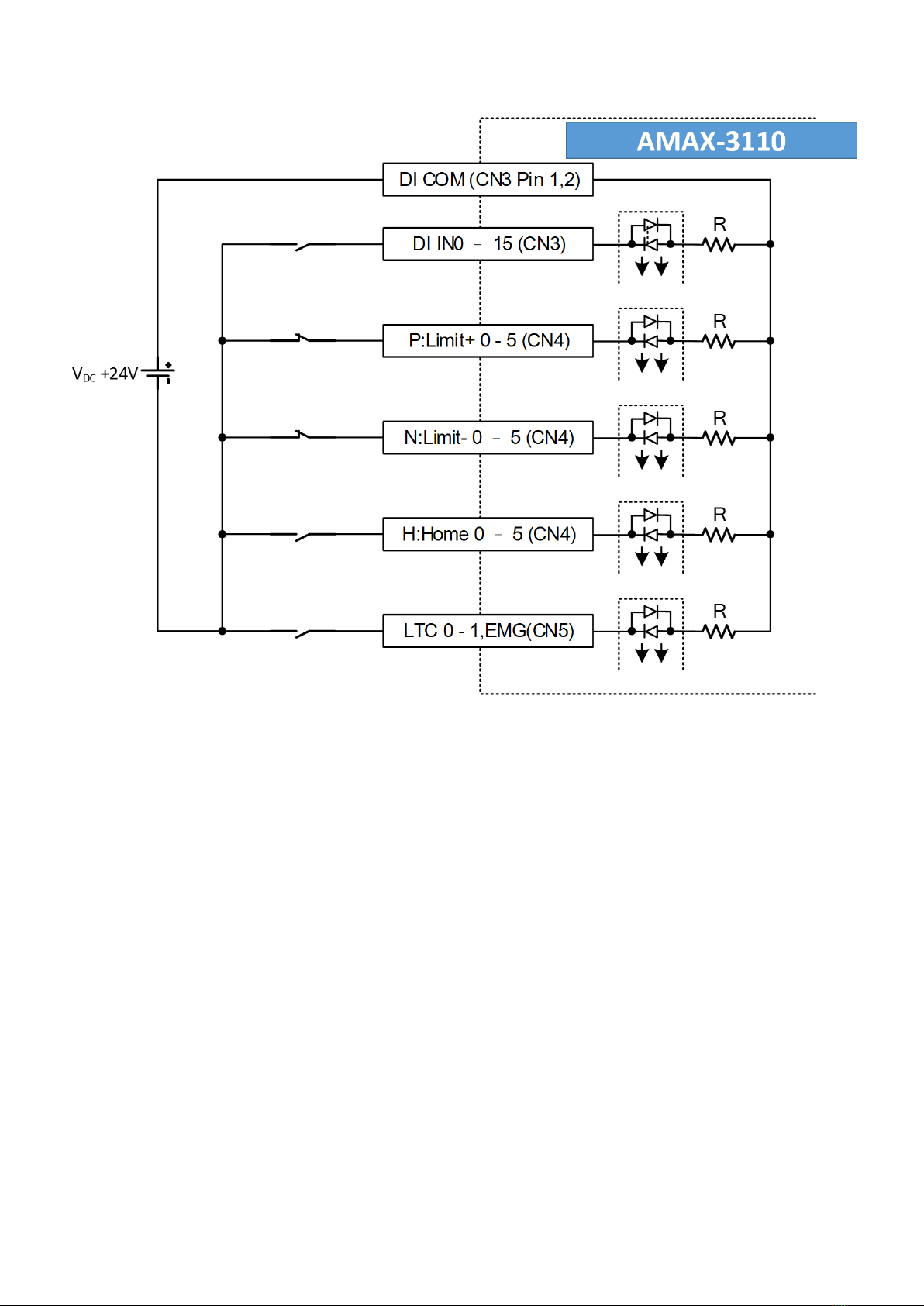
2.4 CN3, CN4, CN5 (Digital Input)
2.4.1 CN3(General Input) Pin Definition
Pin
Name
Description
1
COM
DI COM.
2
COM
DI COM.
3
IN8
General Digital Input 8
4
IN0
General Digital Input 0
5
IN9
General Digital Input 9
6
IN1
General Digital Input 1
7
IN10
General Digital Input 10
8
IN2
General Digital Input 2
9
IN11
General Digital Input 11
10
IN3
General Digital Input 3

12
AMAX-3100 用戶手冊
11
IN12
General Digital Input 12
12
IN4
General Digital Input 4
13
IN13
General Digital Input 13
14
IN5
General Digital Input 5
15
IN14
General Digital Input 14
16
IN6
General Digital Input 6
17
IN15
General Digital Input 15
18
IN7
General Digital Input 7
2.4.2 CN4 (Limit and Home) Pin Definition
Pin
Name
Description
1
P3
Axis 3 Limit +
2
P0
Axis 0 Limit +
3
N3
Axis 3 Limit -
4
N0
Axis 0 Limit -
5
H3
Axis 3 Home(ORG)
6
H0
Axis 0 Home(ORG)
7
P4
Axis 4 Limit +
8
P1
Axis 1 Limit +
9
N4
Axis 4 Limit -
10
N1
Axis 1 Limit -
11
H4
Axis 4 Home(ORG)
12
H1
Axis 1 Home(ORG)
13
AMAX-3100 用戶手冊
13
P5
Axis 5 Limit +
14
P2
Axis 2 Limit +
15
N5
Axis 5 Limit -
16
N2
Axis 2 Limit -
17
H5
Axis 5 Home(ORG)
18
H2
Axis 2 Home(ORG)
2.4.3 CN5 (EMG/CMP/LTC) Pin Definition
Pin
Name
Description
1
EMG
Emergency Stop Input
2
LTC0
Position Latch Input 0
3
LTC1
Position Latch Input 1
4
CMP0
Position Compare Output 0
5
CMP1
Position Compare Output 1
6
CGND
Compare Output Ground
2.4.4 CN3, CN4, CN5 Wiring
14
AMAX-3100 用戶手冊
15
AMAX-3100 用戶手冊
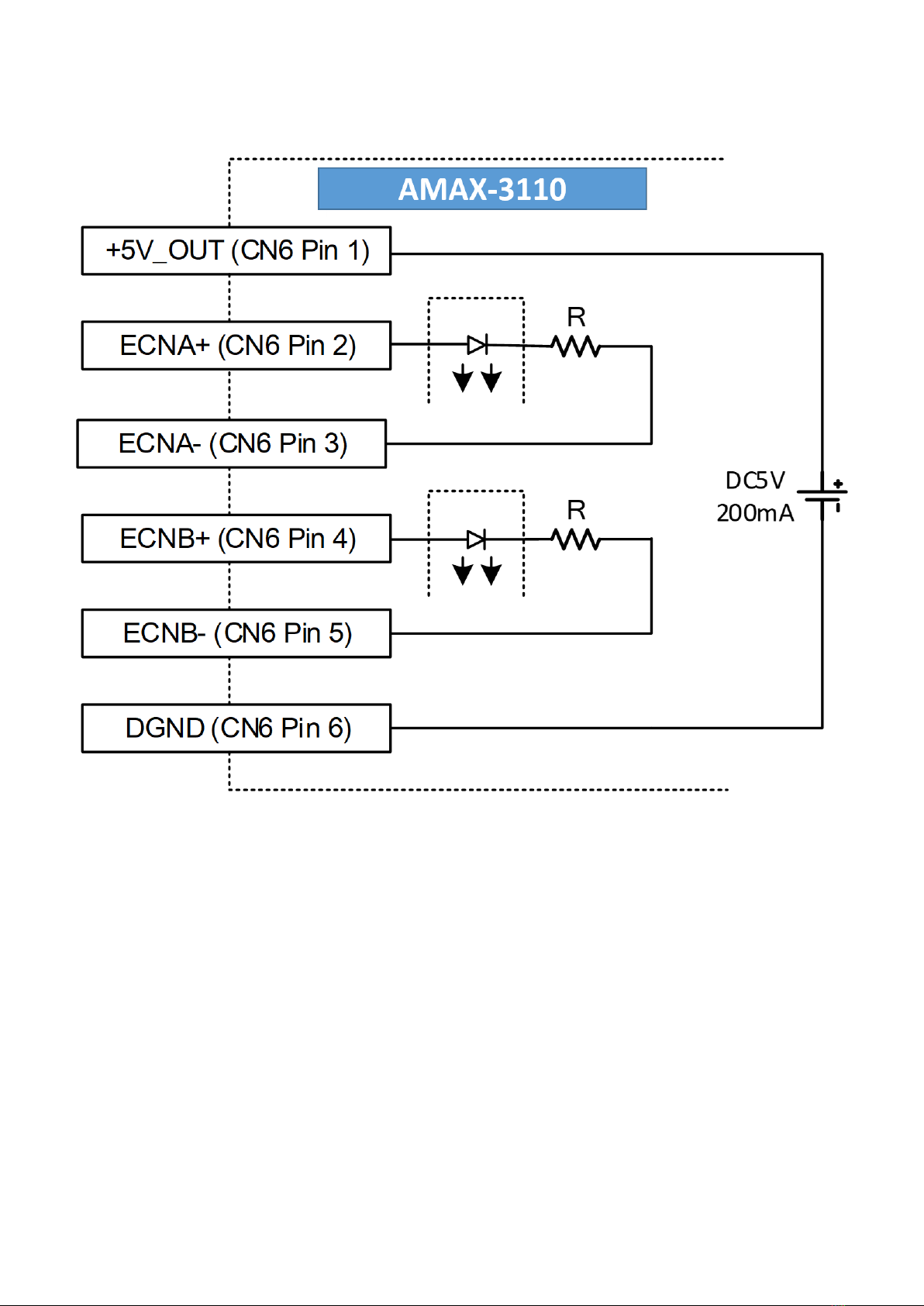
2.5 CN6 (MPG) Handweel
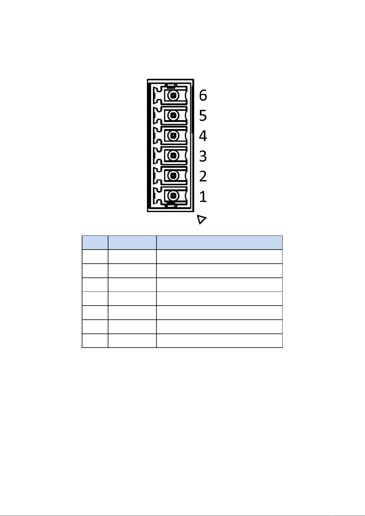
2.5.1 CN6 (MPG) Pin Definition
Pin
Name
Description
1
5V
External Power 5V
2
ENCA+
Encoder Phase A+
3
ENCA-
Encoder Phase A-
4
ENCB+
Encoder Phase B+
5
ENCB-
Encoder Phase B+
6
DGND
5V Ground
6
CGND
Compare Output Ground
16
AMAX-3100 用戶手冊
2.5.2 CN6 Wiring

17
AMAX-3100 用戶手冊
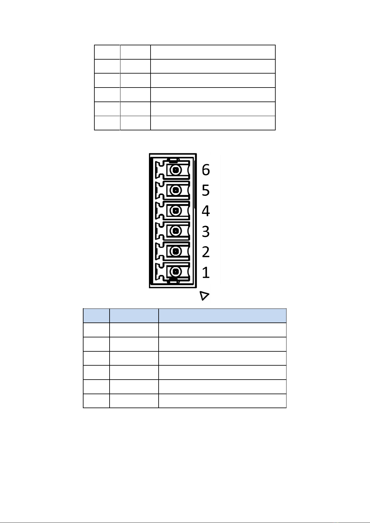
2.6 CN7 (PWM)
2.6.1 CN7 (PWM) Pin Definition
Pin
Name
Description
1
PWM0+
PWM Output 0 +
2
PWM0-
PWM Output 0 -
3
PGND
PWM Ground
4
PWM1+
PWM Output 1 +
5
PWM1-
PWM Output 1 -
6
PGND
PWM Ground
This manual suits for next models
2
Table of contents


