Before using the unit, be sure to read all operating instructions carefully. Please note that these are general
precautions and may not pertain to your particular unit. For example, this unit may not have the capability
to be connected to an outdoor antenna.
1. READ THESE INSTRUCTIONS
All the safety and operating instructions should be read before the product is operated.
2. KEEP THESE INSTRUCTIONS
The safety and operating instructions should be retained for future reference.
3. HEED ALL WARNINGS
All warnings on the product and in the operating instructions should be adhered to.
4. FOLLOW ALL INSTRUCTIONS
All operating and use instructions should be followed.
5. DO NOT USE THIS APPARATUS NEAR WATER
Do not use this product near water (a bathtub, washbowl, kitchen sink, laundry tub, wet
basement, or swimming pool for example)
6. CLEAN ONLY WITH DRY CLOTH
Unplug this product from the wall outlet before cleaning. Do not use liquid cleaners or aerosol cleaners. Use a dry
cloth for cleaning.
7. ATTACHMENTS
8. ACCESSORIES
Do not place this product on an unstable cart, stand, tripod, bracket, or table. The
product may fall, causing serious injury and serious damage to the unit.
8A.
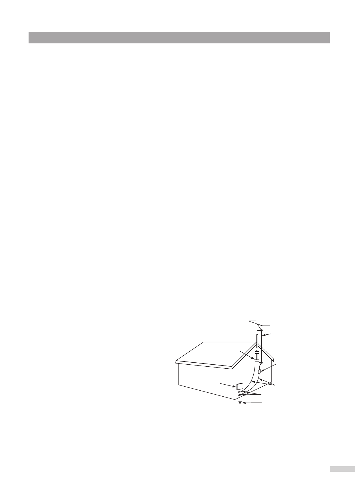
9. VENTILATION
10. POWER SOURCES
This product should be operated only from the type of power source indicated on the marking label. If you are not
sure of the type of power supply to your home, consult your appliance dealer or local power company. For products
intended to operate from battery power, or other sources, refer to the operating instructions.
11. GROUNDING OR POLARIZATION
.
12. POWER-CORD PROTECTION
Only use attachments/accessories specified by the manufacturer.
Use only with the cart, stand, tripod, bracket, or table specified by the manufacturer, or
sold with the apparatus. When a cart is used, use caution when moving the
cart/apparatus combination to avoid injury from tip-over.
Do not block any ventilation openings. Install in accordance with the manufacturer’s instructions.
Do not install near any heat sources such as radiators, heat registers, stoves, or other apparatus (including amplifiers)
that produce heat.
Do not defeat the safety purpose of the polarized or grounding-type plug. A polarized plug has two blades with one
wider than the other. A grounding type plug has two blades and a third grounding prong. The wide blade or the third
prong are provided for your safety. If the provided plug does not fit into your outlet, consult an electrician for
replacement of the obsolete outlet
Protect the power cord from being walked on or pinched particularly at plugs, convenience receptacles, and the point
where they exit from the apparatus.
The lightning flash with arrowhead symbol,
within an equilateral triangle is intended to
alert the user to the presence of uninsulated
dangerous voltage within the product's
enclosure that may be of sufficient magnitude
to constitute a risk of electric shock to persons.
The exclamation point within an equilateral
triangle is intended to alert the user to the
presence of important operating and
maintenance (servicing) instructions in the
literature accompanying the appliance.
RISK OF ELECTRIC SHOCK
DO NOT OPEN
CAUTION
Important Safety Instructions
1
PORTABLE CART WARNING
(symbol provided by RETAC)
S3126A
WARNING: To reduce the risk of fire or electric shock, do not expose this apparatus to rain or moisture.
CAUTION-These servicing instructions are for use by
qualified service personnel only. To reduce
the risk of electric shock, do not perform any
servicing other than that contained in the
operating instructions unless you are
qualified to do so.