The product is an advanced line-interactive UPS based on microprocessor control. This
means that it operates with the newest technology, high performance and powerful function.
The line-interactive UPS is an intelligent protector and provides pure, reliable AC power to
the critical loads - protecting them from utility power blackout, swells, sags, surges and
interference. The loads could include sensitively medical instruments, computers,
telecommunication systems, and industrially automatic equipment. Under power normal
condition, the line-interactive design enables the system to adjust and filter power
fluctuations continuously and automatically. In the event of power failure, it can provide
immediately back-up power from the batteries without any interruption. Complete
transference will be achieved within 4m seconds, with no interruption.
Beside this, when the utility power is connected, the charger would work automatically
even under power switch is OFF. Furthermore, in order to save the battery energy, UPS can
automatically turn it off under backup mode if none of the connected loads is operating.
Advanced battery management
The visual and audible indications of the UPS present the battery’s status including capacity
degree and battery condition. Self-test function let UPS detect a weak battery before it is put
into service. The UPS normally perform a self-test at power up and manual self-test
condition. Self-test function can be conducted manually with the ON/TEST switch at any
time.
Advanced monitoring software
The line-interactive UPS and UPS-MON series monitoring software (optional kits) make
your computer operate intelligent and provide you with the ability of perfect protection of
your critical devices. The software is available for most operation systems and is supplied
with a communication cable that connects to the UPS.
Note: There is no guarantee that interference to radio/TV will not occur in a particular
installation. If this UPS causes interference to radio or television reception, which can be
determined by turning the UPS off and on, the user is encouraged to try to correct the
interference by one or more of following measures:
1. Connect the equipment to an outlet at a circuit different from the connected radio/TV.
2. Increase the separation between the equipment and the receiver or reorient the receiving
antenna.
1. PRESENTATION
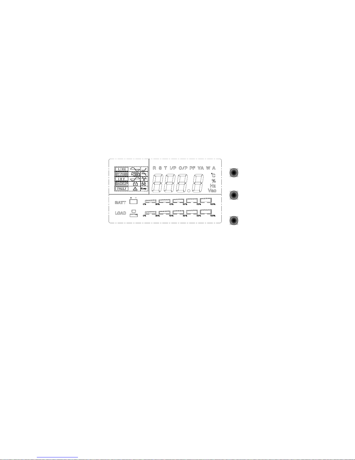
1.1 Front LED Panel
1.1.1 “ON/TEST” button: With the UPS plugged in, press the ON/TEST button to turn
on the UPS and power the loads. ON/TEST also activates the UPS‘s self-test and utility line
voltage displays.
1.1.2 “OVERLOAD” indicator (RED LED): The LED lights when the loads connected
to the UPS exceed the UPS‘s capacity. See Section 5.3.
1.1.3 “BACK UP” indicator (GREEN LED): The LED illuminates when the UPS is
supplying battery power to the loads.


 Plus Startup manual")


