AEB SUB 18D User manual

A.E.B. INDUSTRIALE s.r.l.
Via Brodolini, 8 - 40056 Crespellano (Bo) - ITALIA
Tel. + 39 051 969870 - Fax. + 39 051 969725
Internet: www.dbtechnologies.com
E-mail: [email protected]
MANUALE D’USO
USER MANUAL
BEDIENUNGSANLEITUNG
CARACTERISTIQUES TECHNIQUES
Made in Italy
COD. 420120144
digital power
RR
PROFESSIONAL ACTIVE
SUBWOOFER SPEAKER
SUB 18DSUB 18D
SUB 15DSUB 15D
SUB DSUB D

ItalianoItalianoItaliano
Manuale d’usoManuale d’uso
ItalianoItalianoItaliano
Manuale d’usoManuale d’uso
Acqua e umidità
L'apparecchio non deve essere installato in prossimità di zone con presenza di liquidi ( es. lavandini,
lavabi, docce, vasche da bagno, bordo piscine, pavimenti bagnati o in altre posizioni in presenza di
acqua e liquidi in generale).
Penetrazione di oggetti e di liquidi
L’apparato deve essere posizionato in un luogo appropriato. Evitare di posizionare oggetti e contenitori
di liquidi sopra l’apparato, un ribaltamento accidentale potrebbe causarne l’intrusione all’interno delle
griglie di raffreddamento con conseguente pericolo elettrico.
Ventilazione
Installare l’apparecchio in una posizione o zona adeguata, tale da garantire un sufficiente ricircolo
d’aria. Non ostruire o coprire le feritoie di aerazione e ventilazione o i dissipatori dell’apparato. E’ buona
norma installare l’apparato ad una distanza che garantisca una buona ventilazione tra gli apparati.
Sorgenti di calore
Non installare o utilizzare l'apparecchio in prossimita’di sorgenti di calore .
Accessori e optional
E’ assolutamente vietato perforare il contenitore dell’apparato o fissare qualunque altro genere di
supporto meccanico mediante adesivo. In caso di installazioni particolari e in ogni modo non descritte
nel presente manuale, contattare il servizio tecnico per l’elenco degli accessori disponibili per
l’apparato.
Seguire tutte le istruzioni
Tutte le istruzioni contenute nel presente manuale devono essere seguite da parte dll’utilizzatore per un
corretto utilizzo e funzionamento dell’apparato. In particolare si pone l’attenzione su:
- Non forzare gli organi di comando (tasti, controlli, ecc.).
- evitare di far lavorare l’apparato in sovraccarico per lungo tempo.
Pulizia
Pulire solo con un panno asciutto. Per la pulizia delle parti esterne evitare l’uso di diluenti, alcool,
benzina o altre sostanze volatili.
COLLEGAMENTI
ATTENZIONE
-Per il collegamento dell’apparecchio si raccomanda di rivolgersi a personale qualificato ed
addestrato, ossia personale avente conoscenze tecniche o esperienza o istruzioni specifiche
sufficienti per permettergli di realizzare correttamente le connessioni e prevenire i pericoli
dell’elettricità.
-Per evitare il rischio di shock elettrici, l’amplificatore deve essere alimentato dalla tensione di rete
solo dopo aver terminato tutti i collegamenti.
-Prima di alimentare l’amplificatore è buona norma ricontrollare tutte le connessioni.
- Tutto l’impianto di sonorizzazione dovrà essere realizzato in conformità con le norme e le leggi
vigenti in materia di impianti elettrici.
SUGGERIMENTI
ATTENZIONE
- Per evitare che fenomeni induttivi diano luogo a ronzii, disturbi e compromettano il risultato
dell’installazione, i cavi che trasmettono segnali microfonici o segnali a livello linea (es. 0 dB/V)
devono essere schermati e non devono essere posti in prossimità di:
1) apparecchiature che producono forti campi magnetici (es. grossi trasformatori di
alimentazione).
2) conduttori dell’energia elettrica.
3) linee che alimentano diffusori.
IMPORTANTI ISTRUZIONI DI SICUREZZA
AVVERTENZA: PER RIDURRE IL RISCHIO DI SCOSSA
ELETTRICA, NON TOGLIERE IL COPERCHIO
(O IL PANNELLO POSTERIORE).ALL’INTERNO
NON SONO CONTENUTE PARTI RIPARABILI
DALL’UTENTE; AFFIDARE LE RIPARAZIONI A
PERSONALE QUALIFICATO.
ATTENZIONE: PER RIDURRE IL RISCHIO DI INCENDIO O DI
SCOSSA ELETTRICA, NON ESPORRE
QUESTO APPARECCHIO ALLA PIOGGIA O
ALL’UMIDITÀ.
Questo simbolo, dove compare, ha lo scopo di avvisare l’utente di presenza di tensione
pericolosa all’interno del prodotto che può essere di portata sufficiente a costituire un rischio di
scossa elettrica per le persone.
Questo simbolo, dove appare, ha lo scopo di avvisare l’utente di presenza di importanti
istruzioni d’uso e manutenzione (assistenza) nella documentazione che accompagna
l’apparecchio.
IMPORTANTE
Il presente manuale costituisce parte integrante del prodotto e deve accompagnare quest’ultimo anche
nei passaggi di proprietà, per permettere al nuovo proprietario di conoscere le modalità d’installazione e
d’utilizzo e le avvertenze per la sicurezza.
L’installazione ed utilizzo non in accordo con le prescrizioni e modalità contenute all’interno del presente
manuale d’uso esime il produttore da qualunque responsabilità di danni a persone, cose e strutture.
Leggere le seguenti ist ruz ion i
Tutte le istruzioni di sicurezza e di funzionamento devono essere lette e comprese prima di mettere in
funzione l'apparato.
Tenere conto di tutti gli avvertimenti
Tutte le avvertenze sull'apparecchio e le istruzioni di funzionamento devono essere seguite fedelmente.
Inutilizzo prolungato dell’apparato
Guasti e riparazioni
In caso di guasto dell’apparato, è assolutamente vietato per l'utente tentare di ripararlo o rimuovere il
coperchio protettivo. Disconnettere l’apparato dalla rete di alimentazione e contattare l’assistenza
tecnica per la riparazione.
PRECAUZIONI PER L’INSTALLAZIONE E PER L’UTILIZZO
GENERALITA’
Conservare le istruzioni
Ai fini di un corretto impiego dell’apparato, il presente manuale d’istruzioni deve essere mantenuto con
cura per o gni f utu ra es ige nza d i con sul tazione.
Posizionamento dell’apparato
Collocare l’apparato in posizione stabile e sicura in modo da evitare situazioni di pericolo a cose,
persone e strutture.
Messa a terra di protezione
L’apparato è realizzato in Classe I di protezione contro la scossa elettrica e il collegamento alla rete di
alimentazione deve essere effettuato ad una presa provvista del conduttore di terra di protezione. Prima
di effettuare la connessione elettrica dell’apparato, assicurarsi che l’impianto di distribuzione di rete sia
conforme alle norme vigenti in materia di impianti elettrici.
Alimentazione
L'apparato deve essere collegato ad una sorgente di alimentazione del tipo e con le caratteristiche
indicate nei dati di targa riportati sull'apparecchio stesso e specificati nel presente manuale (Vedere
specifiche tecniche). Prima di collegare la spina di alimentazione assicurarsi che la tensione sia del tipo
richiesto dall’apparato.
Cavo di alimentazione
Al fine di garantire la sicurezza d’utilizzo dell’apparato utilizzare esclusivamente il cavo di alimentazione
fornito a corredo avendo cura di posizionarlo e proteggerlo in modo da evitarne il danneggiamento
durante l’utilizzo. In caso di danneggiamento contattare l’assistenza tecnica e richiederne la
sostituzione. Non utilizzare cavi diversi da quelli in dotazione.
Nel caso in cui si preveda di non utilizzare l’apparato per lungo tempo, è buona norma disconnetterlo
dalla rete di alimentazione, riporlo nell’apposito imballo o ricoprirlo in maniera da evitarne l’esposizione
alla polvere.
12
“CAUTION”
TO PREVENT ELECTRICAL SHOCK
DO NOT REMOVE COVER
“AVIS”
RISQUE DE CHOCH ELECTRIQUE
NE PAS OUVRIR

ItalianoItalianoItaliano
Manuale d’usoManuale d’uso
34
ItalianoItalianoItaliano
Manuale d’usoManuale d’uso
DESCRIZIONE
I diffusori della serie “SUB D” sono equipaggiati con amplificatore in classe D della serie
®
DIGIPRO . Questi amplificatori, ad alta efficienza, permettono di ottenere elevate potenze
di uscita con pesi e ingombri ridotti. Grazie alla bassa potenza dissipata il raffreddamento
del modulo amplificatore avviene in modo statico, evitando l’uso di ventola.
®
Il circuito di alimentazione dell’amplificatore DIGIPRO , montato sul diffusore SUB 15D, è
stato progettato per essere settato in funzione della tensione di alimentazione e progettato
con tecnologia SMPS (Switched-Mode Power Supplies)
®
Il circuito di alimentazione dell’amplificatore DIGIPRO , montato sul diffusore SUB 18D, è
stato progettato per funzionare in modalità full-range; grazie alla tecnologia SMPS
(Switched-Mode Power Supplies) con PFC (Power Factor Correction) viene garantito il
funzionamento a tensioni di alimentazioni da 100Vac a 240Vac, garantendo stesse
prestazioni acustiche anche con linee di alimentazione fluttuanti e non stabilizzate.
SUB D è una serie di subwoofer attivi in legno di betulla, studiati per sonorizzare ambienti
medio grandi; sono costruiti utilizzando la tipologia “BAND PASS” che permette di ottenere
alte pressioni acustiche in dimensioni ridotte.
Entrambe i diffusori sono stati progettati per l’utilizzo in appoggio.
Per facilitare l’utilizzo, l’installazione e il trasporto sono provvisti di:
-maniglie laterali
-supporto con filetto M20 per asta
-sedi per appoggio di diffusori a due vie serie FLEXSYS o altro subwoofer nella parte
superiore del box.
- predisposizione per ruote (solo SUB 18D)
I diffusori sono stati progettati per funzionare in modalità stereo o modalità mono.
E’ possibile settare la frequenza di incrocio (90Hz oppure 120Hz) e la rotazione di fase (0°
oppure 180°). I segnali di uscita possono essere link oppure pilotati dall’uscita XOVER.
CARATTERISTICHE
Il raffreddamento dell’amplificatore avviene attraverso il pannello in alluminio posto sul
retro del diffusore stesso.
La protezione termica è garantita da un circuito interno che controlla la temperatura
dell’amplificatore stesso e lo protegge dal surriscaldamento limitando il volume generale
(con temperatura >70°).
Se la temperatura raggiunge quella massima di utilizzo (>80°), il segnale audio viene posto
in stato di “mute” e verrà segnalato tramite l’accensione dell’indicatore luminoso giallo
“MUTE”.
Il corretto volume e tutte le funzioni verranno riprese automaticamente al raggiungimento
delle normali temperature di esercizio.
L’accesione dell’indicatore luminoso giallo “MUTE” indica che l’amplificatore ha rilevato un
malfunzionamento sul diffusore, ponendolo in stato di mute.
Eseguire le seguenti verifiche:
- Controllare la corretta connessione alla rete d’alimentazione.
- Assicurarsi della corretta tensione d’alimentazione.
- Controllare che l’amplificatore non sia surriscaldato.
- Scollegare dalla rete di alimentazione il diffusore, attendere qualche minuto e
riprovare
Se dopo tale prove l’indicatore non si spenge contattare un centro assistenza autorizzato.
Raffreddamento
Protezione
COLLEGAMENTI
Collegamento alla alimentazione di rete
Ogni diffusore attivo è provvisto del proprio cavo di alimentazione. Il collegamento
avviene tramite un connettore modello Neutrik POWER CON® (blu) che permette di
avere una facile e rapita connessione al diffusore oltre che a un ottimo sistema di
bloccaggio.
Lo stesso connettore svolge la funzione di interruttore di rete.
L’apparecchio dovrà essere collegato ad una rete di alimentazione che possa erogare la
massima potenza richiesta.
Rilancio alimentazione di rete
Sul retro del diffusore è presente un connettore Neutrik POWER CON® (grigio) per il
rilancio dell’ alimentazione di rete.
Questa presa ha lo scopo di rilanciare l’alimentazione ad un altro diffusore riducendo i
collegamenti diretti alla rete. Gli assorbimenti massimi degli amplificatori sono riportati
sul pannello dell’amplificatore.
Il numero massimo dei diffusori collegati insieme varia sia per gli assorbimenti massimi
dei diffusori e sia dalla corrente massima della prima presa di alimentazione.
INSTALLAZIONE DEL DIFFUSORE
ATTENZIONE
Installare il diffusore in modo stabile e sicuro, così da evitare qualsiasi condizione di
pericolo per l’incolumità di persone e strutture.
Per evitare condizioni di pericolo non sovrapporre fra loro più diffusori senza adeguati
sistemi di ancoraggio.
Nell’utilizzo all’aperto evitare luoghi esposti alle intemperie.
Il diffusore viene fornito dalla ditta costruttrice predisposto per l’utilizzo in appoggio
ATTENZIONE
Non utilizzare mai le maniglie per appendere il diffusore!

ItalianoItalianoItaliano
Manuale d’usoManuale d’uso
56
ItalianoItalianoItaliano
Manuale d’usoManuale d’uso
COMANDI E FUNZIONI
1) CONNETTORI INGRESSO " BALANCED INPUT 1” e " BALANCED INPUT 2”
Connettori “XLR” di ingresso bilanciato a livello linea .
2) CONNETTORI DI USCITA "OUT 1”e "OUT 2”
I connettori “XLR” sono utilizzati per inviare il segnale audio ad un altro diffusore
amplificato.
Il tipo di segnale è selezionabile tramite l’interruttore” LINK/XOVER” (10)
3) INDICATORE LUMINOSO “LIMITER”
Questo indicatore s’illumina di colore rosso per indicare l'intervento del circuito
limitatore interno, il quale evita la distorsione dell'amplificatore e protegge gli
altoparlanti da sovraccarichi.
4) INDICATORE LUMINOSO “SIGNAL”
Questo indicatore s'illumina di colore verde per indicare la presenza del segnale
audio (ad un livello di -20dB).
5) INDICATORE LUMINOSO “MUTE”
Questo indicatore di colore giallo indica lo stato dell’amplificatore.
Nel normale funzionamento il led è spento.
6) INDICATORE LUMINOSO “READY”
Questo indicatore s'illumina di colore verde per indicare che la tensione di
alimentazione di rete è corretta.
Nel normale funzionamento il led è acceso.
7) CONTROLLO SENSIBILITA’IN GRE SSO “IN PUT SEN S”
Questo controllo regola la sensibilità del segnale in ingresso all’amplificatore.
Tale controllo non influisce sul livello dell’uscita “OUT 1” e “O UT 2”
8) SELETTORE “PHASE”
Questo interruttore a due posizioni permette la rotazione di 180°del segnale audio
riprodotto dal subwoofer.
La rotazione facilita l’ottimizzazione della riproduzione alle basse frequenze anche
nelle situazioni di installazioni difficili. Completata l’installazione, riprodurre un brano
musicale ed agire sull’interruttore per ottenere la migliore resa acustica alle basse
frequenze.
9) SELETTORE “XOVER”
Questo interruttore permette di selezionare la frequenza di incrocio tra subwoofer e i
diffusori collegati alle uscite “OUT 1” e “OUT 2”. La scelta del taglio è legata al tipo di
diffusore che si utilizza per la riproduzione delle frequenze medio-alte.
Per i diffusori con i coni a 12” è consigliabile utilizzare un taglio a 120Hz, mentre con i
diffusori con coni da 15” usare un taglio a 90Hz.
10) SELETTORE “LINK/XOVER”
Questo interruttore permette di selezionare il segnale da rilanciare sulle uscite “OUT
1” e “OUT 2”.
La posizione “LINK” permette di rilanciare lo stesso segnale di ingresso .
La posizione “XOXER” permette d’ inviare il segnale di ingresso tagliato alla
frequenza di incrocio selezionata tramite il selettore “XOVER” (9)
11) PRESA D I ALIMENTAZIONE “MAINS INPUT”
Consente la connessione del cavo di alimentazione e svolge la funzione di
interruttore di rete .
Il connettore utilizzato per il collegamento alla rete è un POWER CON® (blu)
12) PRESADI ALIMENTAZIONE RILANCIO “MAINS OUTPUT LINK”
Consente di rilanciare l’alimentazione di rete. L’uscita è connessa in parallelo con
l’ingresso (11) e può essere utilizzata per alimentare un altro diffusore amplificato.
Il connettore utilizzato è un POWER CON® (grigio).
13) PORTAFUS IBILE “ MAINS F USE”
Alloggio per fusibile di rete.
DATI TECNICI
SUB 15D SUB 18D
Sistema Attivo Attivo
Tipologia amplificatore Classe D Classe D
Potenza RMS 800W 1000W
Risposta in frequenza 40-120Hz (-3dB) 35-120Hz (-3dB)
Crossover 90Hz - 120Hz selezionabile 90Hz - 120Hz selezionabile
24dB/oct 24dB/oct
Pressione sonora (max SPL) 133dB 134dB
Componenti 1x15” woofer - 3” voice coil 1x18” woofer - 4” voice coil
Sensibilità ingresso max -3dBu max -3dBu
Impedenza ingresso Bilanciato 20Kohm Bilanciato 20Kohm
Sbilanciato 10Kohm Sbilanciato 10Kohm
Alimentazione Selezionabile internamente Full-range con PFC
100-120Vac 50-60Hz 100-240Vac 50-60Hz
220-2400Vac 50-60Hz
Forma diffusore Rettangolare Rettangolare
Colore diffusore Nero Nero
Dimensioni (WxHxD) 436x600x600mm 530x700x600mm
Peso 32Kg 44Kg
Supporto piantana M20(alluminio) 2 x M20 (alluminio)
Maniglie 2 (1x per lato) 4 (2x per lato)

IMPORTANT SAFETY INSTRUCTIONS
CAUTION: TO REDUCE THE RISK OF ELECTRICAL
SHOCK, DO NOT REMOVE THE COVER
(OR BACK). NO USER SERVICEABLE
PARTS INSIDE; REFER SERVICING TO
QUALIFIED PERSONNEL.
WARNING: TO REDUCE THE RISK OF FIRE OR
ELECTRICAL SHOCK. DO NOT
EXPOSE THIS APPLIANCE TO RAIN OR
MOISTURE.
This symbol, wherever it appears, alerts you to the presence of uninsulated dangerous
voltage inside the enclosure - voltage that may be sufficient to constitute a risk of shock.
This symbol wherever it appears, alerts you to important operating and maintenance
instructions in the accompanying literature. Read the manual.
INSTALLATIONAND OPERATING PRECAUTIONS
GENERAL
IMPORTANT NOTES
This manual is to be considered an integral part of the product, and must always accompany the
equipment when it changes ownership, as a reference for correct installation and operation as well as
for the safety regulations. The Manufacturing company will not assume any responsibility for incorrect
installation of the amplifier.
Read these instructions
All the safety and operation instructions should be read before the appliance is operated.
Heed all Warnings
All warnings on the appliance and in the operating instructions should be adhered to
Long period non use of equipment
If long term non use of appliance is expected, it would be better to unplug this apparatus from power
supply, put it into proper packaging and cover to avoid dust exposure.
Damage and repair
If apparatus has been damaged it is forbidden to repair it or to remove cover. Disconnect the unit from
the mains power and contact technical assistance for repair.
Keep these instructions
For a correct use of the appliance, the safety and operating instructions should be retained for future
reference.
Apparatus positioning
Make sure that the apparatus is positioned in a stable and secure way in order to avoid any dangerous
conditions for persons or objects.
Grounding protection
The apparatus is made in protection CLASS I to prevent the risk of electrical shock the appliance must
be connected to a mains socket outlet with a protective earthing connection. Before making the
electrical connection of the appliance, ensure that the electrical distribution network conforms to the
regulations regarding electrical equipment.
Power Source
The appliance should be connected to a power supply only of the type described in the operating
instructions or as marked on the appliance (see “Specifications”). In order not to jeopardize the safety
of the amplifier, it must only be connected to the mains using the power cable provided.
Power Cord Protection
To ensure a safe use of appliance, use only the power cord supplied with the equipment, taking care to
place it and protect it to avoid damage during use. If power cord becomes damaged contact technical
assistance and request replacement. Do not use cables other than supp lie d ca ble s.
Water and Moisture
Do not install this apparatus near water (e.g. near washbasins, sinks, showers, bathtubs, swimming
pool, wet floors or anything in the presence of water and liquids in general).
“CAUTION”
TO PREVENT ELECTRICAL SHOCK
DO NOT REMOVE COVER
“AVIS”
RISQUE DE CHOCH ELECTRIQUE
NE PAS OUVRIR
EnglishEnglishEnglish
user manualuser manual
8
Object and Liquid Entry
The apparatus must be placed in inappropriate position. Care should be taken so that objects do not
fall and liquids are not spilled into the enclosure through cooling grid with consequent electrical
danger.
Ventilation
The appliance should be situated so that its location or position does not interfere with its proper
ventilation. Do not block or cover any openings of the grid ventilation or heatsink. Install the apparatus
at a distance that ensures a good ventilation between devices.
Heat
Do not install the appliance near any source of heat.
Accessories and installation
For a safe installation, do not make any holes in the external chassis for the application of additional
brackets. In case of particular installations not described in this manual, contact technical service for
accessories specified by the manufacturer.
Follow the instructions
All operations and instructions in this user manual should be followed for a correct operation and
function of appliance. Pay attention in particular to:
-Never force the control elements (switches, controls, etc.).
-Do not force the amplifier to work in overload for extended periods of time.
Cleaning
Clean only with a dry cloth. Do not use solvents, alcohol, benzene or volatile substances for cleaning
the exterior parts.
CONNECTION
-For connecting the appliance, use only qualified and experienced personnel having sufficient
technical knowledge or specific instructions for making the connections correctly and thus
preventing electrical dangers.
- To prevent the risk of electrical shock, the appliance must only be supplied from the mains after
all connections have been completed.
-Before powering up the appliance, it is advisable to re-check all the connections.
-The entire sound system must be designed and installed in compliance with the current
standards and regulations regarding electrical systems.
SUGGESTIONS
CAUTION
To prevent inductive phenomena from giving rise to hum or disturbance which would jeopardize
efficient appliance operation, the cables that transmit microphone signals or line level signals (e.g. 0
dB/V) must be screened and should not be run in the vicinity of:
1) Equipment that produces strong magnetic fields (e.g. large power supply transformers)
2) Electrical energy conductors
3) Lines that supply speakers.
CAUTION
user manualuser manual EnglishEnglishEnglish
7

EnglishEnglishEnglish
user manualuser manual
10
user manualuser manual EnglishEnglishEnglish
9
DESCRIPTION
®
The ”SUB D” series speakers are equipped with DIGIPRO series class D amplifier.
These high-efficiency amplifiers deliver high output power in a compact size and low
weight. Thanks to its high efficiency, the cooling of the amplifier module is obtained
statically, thus avoiding the use of a fan.
®
The power supply circuit of the DIGIPRO amplifier, assembled on SUB 15D speaker, has
been designed to work according to power supply voltage and to the SMPS (Switched-
Mode Power Supplies) technology.
®
The power supply circuits of the DIGIPRO amplifier, assembled on SUB 18D, has been
designed to work in full-range mode; thanks to the SMPS (Switched-Mode Power Supplies)
technology with PFC (Power Factor Correction) the operation with supply voltages between
100 Vac and 240Vac is guaranteed by ensuring the same sound performances even with
floating and non-stabilized power supply systems.
SUB D is a series of active subwoofers made of birch wood, designed for medium to large
size rooms. The subwoofer speaker is made using “BAND PASS” so that high sound
pressures can be achieved in compact dimensions.
For easy use, installation and transport, all subwoofers are provided with:
-handles on sides
-standard (M20) pole mount plate
-top part of the box features recesses for making it easier to superimpose the
FLEXSYS series tops or another subwoofer.
-wheels predisposition (only SUB 18D)
The speakers are active sub-woofers designed to function in stereo and in mono modes. It
is possible to set crossover frequency (90Hz or 120Hz) and turning of phase (0° or 180°).
The output signals can be linked or controller by X-OVER output.
CHARACTERISTICS
Cooling
The amplifier is cooled by means of the aluminium panel placed on the back of the speaker.
The thermal protection is ensured by an internal circuit which controls the temperature of
the amplifier and protects this against any risk of overheating thus limiting the general
volume ( temperature >70°C).
If the temperature reaches the maximum operating temperature (>80°C), the audio signal
is set to the “MUTE” position and it will be indicated by the switching on of the yellow
“MUTE” LED.
The requiriered volume and all functions will be restored automatically when the normal
operating temperatures are reached.
Protection
When the yellow “MUTE” LED turns on, it means that a malfunction has been detected on
the speaker, thus setting this to the mute position.
Perform the checks listed below:
- Check if the speaker is properly connected to the power supply.
-Make sure that the power supply is of correct voltage.
- Check that the amplifier is not overheated.
- Disconnect the speaker from the mains power supply, wait for a few minutes and
connect it again.
If after these tests the yellow “MUTE” LED is still on, please contact an authorised service
centre.
CONNECTIONS
Connecting to the mains supply
Each active speaker features its own power cable. Connection is done by a Neutrik
POWER CON® (blue) model which permits easy and fast connection to the speaker as
well as being an excellent locking system.
The same connector serves as a switch to turn ON and OFF the active loudspeaker by
turning the connector to the left (OFF) or right (ON).
The active speaker must be connected to a power supply able to deliver the maximum
required power.
Main power supply linking
On the rear of the speaker, a Neutrik POWER CON® connector (grey) offers linking the
mains power supply.
This socket links the power supply to another speaker, thereby reducing the direct
connections to the mains. Maximum amplifier input power is shown on the amplifier panel.
The maximum number of speakers connected together varies of max in put pow er and of
the maximum allowed current of the first power socket.
WARNING
Never use the handles to hang the speaker!
LOUDSPEAKER INSTALLATION
WARNING
Make sure that the loudspeaker is securely installed in a stable position to avoid any
injuries or damages to persons or property.
For safety reasons do not place one loudspeaker on top of another without proper fastening
systems.
If you use the loudspeakers outdoors avoid places that are exposed to bad weather.
The loudspeaker is supplied by the manufacturer company for use in support

user manualuser manual EnglishEnglishEnglish
11
EnglishEnglishEnglish
user manualuser manual
12
CONTROLS AND FUNCTIONS
1) "BALANCEDINPUT1” AND"BALANCEDINPUT2”INPUTCONNECT ORS
Balancedinputsatlinelevel. Accept“XLR”sockets.
2) "OUT1 ” AND" OUT2 ” OU TP UT CO NNE CT ORS
The “XLR” connectors be used to send the input audio signal to another amplified
speaker .
Thesignalischoosingbetween“LINK/XOVER”(10)switch.
3) “LIMITER”INDICA TORLIGHT
Thisindicatorshowsredtoindicatethattheinternallimitercircuithastrip ped.
Thisprevent samplifierdistortionandprotect sthespeakersagainstoverloads.
4) “SIGNAL”INDICA TORLIGHT
Thisindicatorshowsgreentoindicatethepresenceoftheaudiosignal (at a level of -
20dB).
5) “MUTE”INDICA TORLIGHT
This yellow indicator indicates amplifier status.
The LED is of f in normal operating conditions.
6) “READY”INDICA TORLIGHT
Thisindicatorshowsgreentoindicatethatthemainpowervoltageiscorrect.
TheLEDshows g ree n no rma l ope rat in g con dit ion s
7) “INPUTSENS”INPUTSENSITIVITY C ONT RO L
Thiscontroladjusts t he se ns iti vit y of th e si gna l amp lif ie r inp ut.
Thiscontroldoesnotaf fectthe "OUT 1 ” and " OUT 2 ” ou tp ut s le vels
8) “PHASE”SWITCH
This two-position switch permit s turning the audio signal reproduced by the
subwooferby180°.
Rot ation makesiteasierto optimisethereproductionofthe lowfrequenciesevenin
the mostdif ficult inst allationsituations. Af tercompleting installation,play apiece of
music and move the switch to achieve the best sound reproduction at low
frequencies.
9) “XOVER”SWITCH
This switch permits selecting the crossover frequency between the
subwoofer and the speakers connected to the "OUT 1 ” and "OUT 2 ” out pu ts.
Choice depends on the type of speaker used for reproduction of mid-high
frequencies.
For speakers with 12” cones, it is best to use 120Hz, while with 15”
speakers 90Hz.
10) "LINK/XOVER" SWITCH
This sw it ch al lows to s elect t he si gn al ty pe t o sen d "OUT 1 ” and "OU T 2 ” ou tputs.
The “LINK” position allows to link the same input signal.
The “XOVER” position allows to send input signal according to crossover frequency
select by XOVER (9) switch.
11) "MAINS INPUT" POWER SOCKET
For connecting the power cable provided.
The connector used for mains connection is a POWER CON® (blue) socket
12) “MAINS OUTPUT LINK” POWER SOCKET
For linking the mains power. The output is connected in parallel with input (11) and
can be used to pow er anot her a cti ve s pea ker.
The connector is a POWE R CON® (g rey) so cke t
13) "MAINS FUSE" FUSE CAR RIE R
Mains fuse housing.
TECHNICAL SPECIFICATIONS
System Active Active
Type of a mpl if ier
RMS power
Frequency response
Sound pressure
Components
Input sensitivity
Impedance input Balanced Balanced
Unbalanced Unbalanced
Power supply
Housing shape
Colour Black Black
Dimension (WxHxD)
Weight
Pole mount cup (al umi ni um) ( alu min iu m)
Handle
SUB 15D SUB 18D
Class D Class D
800W 1000W
40 -12 0H z (-3 dB) 35-120Hz (-3dB)
Crossover 90Hz - 120Hz selectable 90Hz - 120Hz selectable
24dB/oct 24dB/oct
(max SPL) 133dB 134dB
1x15” woofer - 3” voice coil 1x18” woofer - 4” voice coil
max -3dBu max -3dBu
20Kohm 20Kohm
10Kohm 10Kohm
Internally selectable Full-range con PFC
100-120Vac 50-60Hz 100-240Vac 50-60Hz
220-2400Vac 50-60Hz
Rectangular Rectangular
436x600x600mm 530x700x600mm
32Kg 44Kg
M20 2 x M20
2 (1x per side) 4 (2x per side)

DeutschDeutschDeutsch
BedienungsanleitungBedienungsanleitung
13
DeutschDeutschDeutsch
BedienungsanleitungBedienungsanleitung
14
SICHERHEITSHINWEISE
WARNUNG: UM STROMSCHLAGGEFAHR ZU
VERMEIDEN, DEN DECKEL (UND DIE
RÜCKPLATTE) NICHT ENTFERNEN. DAS
GERÄT ENTHÄLT KEINE TEILE, DIE DER
BENUTZER REPARIEREN DARF.
REPARATUREN STETS VOM FACHMANN
AUSFÜHREN LASSEN.
ACHTUNG: UM BRAND- UND STROMSCHLAGGEFAHR
ZU VERMEIDEN, DAS GERÄT VOR REGEN
UND FEUCHTIGKEIT SC HÜT ZE N.
Dieses Zeichen soll den Benutzer vor Gefahren durch die elektrische Spannung im
Gerät warnen. Diese elektrische Spannung ist so hoch, dass Stromschlaggefahr
besteht.
Dieses Symbol soll den Benutzer auf wichtige Bedienungs- und Wartungsanweisungen
(Kundendienst) in der dem Gerät beiliegenden Dokumentation hinweisen.
WICHTIG
Dieses Handbuch ist wesentlicher Bestandteil des Geräts und muss dieses auch bei Besitzerwechsel
begleiten, damit der neue Besitzer die Installations- und Gebrauchshinweise sowie die
Sicherheitshinweise kennt.
Die nicht mit den in diesem Handbuch enthaltenen Vorschriften und Modalitäten übereinstimmende
Installation und Verwendung entheben den Hersteller jeder Haftung für Personen-, Sach- und
Anlagenschäden.
Die folgenden Anweisungen lesen
Alle Sicherheits- und Betriebsanweisungen müssen vor der Inbetriebnahme des Geräts gelesen und
verstanden werden.
Alle Warnhinweise berücksichtigen
Alle Warnhinweise für das Gerät und die Betriebsanweisungen müssen getreu befolgt werden.
Längere Nichtbenutzung des Geräts
Wenn eine längere Nichtbenutzung des Geräts abzusehen ist, sollten Sie es vom Versorgungsnetz
abtrennen, es erneut in die entsprechende Verpackung legen oder es so zudecken, dass eine
Staubaussetzung vermieden wird.
Störfälle und Reparaturen
Bei Gerätestörfall ist es dem Benutzer strengstens untersagt, eine Reparatur zu versuchen bzw. den
Schutzdeckel zu entfernen. Das Gerät vom Versorgungsnetz abtrennen und für eine Reparatur mit
dem Kundendienst Kontakt aufnehmen.
VORSICHTSMASSNAHMEN FÜR INSTALLATION UND GEBRAUCH
ALLGEMEINES
Die Anleitungen aufbewahren
Für den korrekten Gebrauch des Geräts muss dieses Handbuch für alle zukünftigen Einsichtnahmen
sorgfältig erhalten werden.
Positionierung des Geräts
Das Gerät in einer stabilen und sicheren Position aufstellen, damit gefährliche Situationen für
Gegenstände, Personen undAnlagen vermieden werden.
Schutzerdung
Das Gerät wurde mit Schutzklasse 1 für den elektrischen Schlag hergestellt und der Anschluss an das
Versorgungsnetz muss mit einem Stecker vorgenommen werden, der mit einem Schutzerdleiter
versehen ist. Vor dem Stromanschluss des Geräts vergewissern Sie sich, dass die Anlage des
Verteilernetzes den in Sachen Elektroanlagen geltenden Richtlinien entspricht.
Netzanschluß
Das Gerät muss an eine Stromquelle mit den Eigenschaften angeschlossen werden, die in den auf
dem Gerät wiedergegebenen Kenndaten angegeben sind und in diesem Handbuch spezifiziert
werden (Siehe technische Spezifikationen). Vor dem Anschluss des Netzsteckers vergewissern Sie
sich, dass die Spannung der vom Gerät verlangten Spannung entspricht.
Stromkabel
Um einen sicheren Gerätegebrauch zu gewährleisten, nur das mitgelieferte Stromkabel verwenden
und darauf achten, dass es so positioniert und geschützt wird, dass Beschädigungen während des
Gebrauchs vermieden werden. Bei Beschädigung mit dem Kundendienst Kontakt aufnehmen und die
Auswechselung veranlassen. Keine anderen als die mitgelieferten Kabel verwenden.
Wasser und Feuchtigkeit
Das Gerät darf nicht in Nähe von vorhandenen Flüssigkeiten (z. B. Spülbecken, Waschbecken,
Duschen, Badewannen, Schwimmbadrändern, nassen Fußböden oder generell in sonstigen
Positionen mit vorhandenem Wasser und Flüssigkeiten) installiert werden.
Eindringen von Gegenständen und Flüssigkeiten
Das Gerät muss einem geeigneten Ort positioniert werden. Das Positionieren von Gegenständen und
Flüssigkeitsbehälter auf dem Gerät vermeiden, ein ungewilltes Umkippen könnte ein Eindringen in
die Kühlgitter und demzufolge eine elektrische Gefahr verursachen.
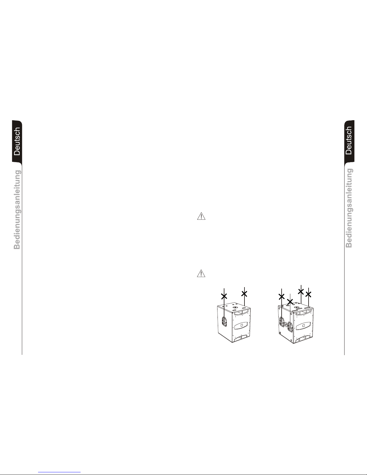
Belüftung
Das Gerät an einem geeigneten Ort oder Bereich installieren, der eine ausreichende Luftzirkulation
gewährleistet. Die Belüftungs- und Ventilationsschlitze bzw. die Kühlkörper des Geräts weder
verstopfen noch bedecken. Es ist angebracht, das Gerät in einer Entfernung zu installieren, die eine
gute Belüftung unter den Geräten gewährleistet.
Wärmequellen
Das Gerät weder in Nähe von Wärmequellen installieren noch benutzen .
Zubehörteile und Opt io n al
Es ist strengstens verboten, das Gehäuse des Geräts zu durchbohren oder irgendeine andere
mechanische Halterung mittels Klebestreifen zu befestigen. Bei Spezialinstallationen und für alle
nicht in diesem Handbuch beschriebenen Weisen wenden Sie sich bitte für die für dieses Gerät
lieferbaren Zubehörteile an den technischen Kundendienst.
Alle Anweisungen befolgen
Alle in diesem Handbuch enthaltenen Anweisungen müssen für einen korrekten Gebrauch und
Betrieb des Geräts vom Benutzer befolgt werden. Insbesondere muss auf Folgendes geachtet
werden:
-Die Bedienelemente (Tasten, Kontrollvorrichtungen, usw.) nicht forcieren.
-Den Betrieb über eine lange Zeit in Überlast vermeiden.
Reinigung
Nur mit einem trockenen Tuch reinigen. Für die Reinigung der Außenteile den Gebrauch von
Verdünnungsmitteln,Alkohol, Benzin oder anderen flüchtigen Substanzen vermeiden.
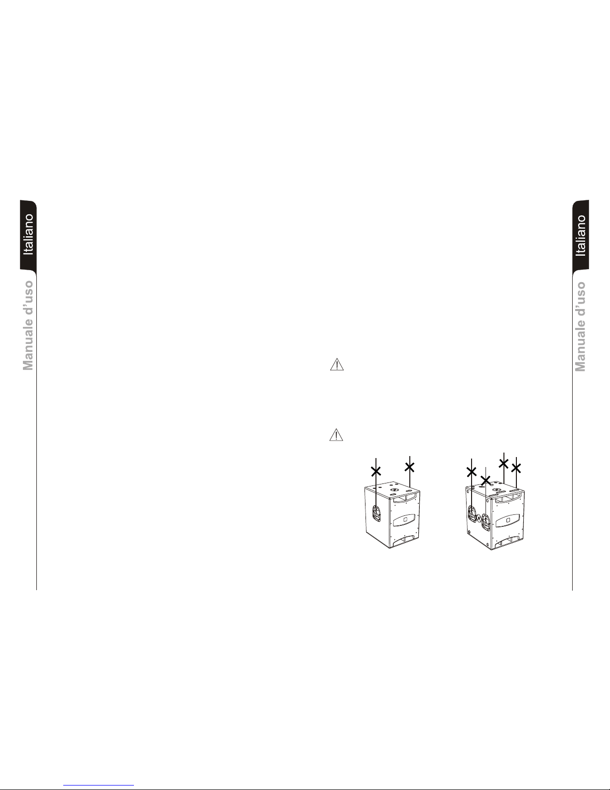
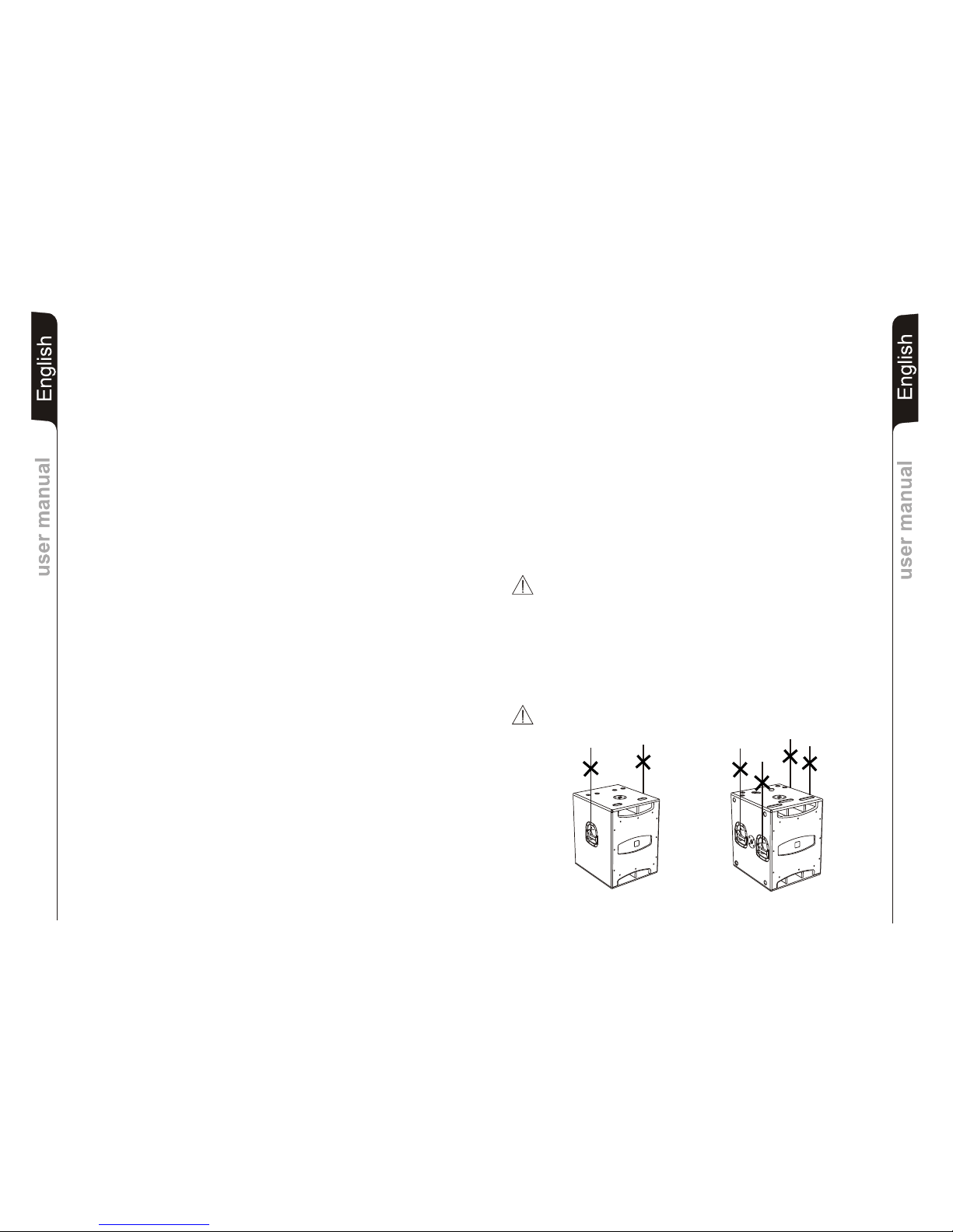
ANSCHLÜSSE
ACHTUNG
-Es wird empfohlen, sich für den Anschluss der Lautsprecherbox an qualifiziertes und
ausgebildetes Personal zu wenden oder aber an Personal, das über eine ausreichende
technische Ausbildung und über die entsprechenden Kenntnisse verfügt, um die Anschlüsse
korrekt auszuführen und die aus der elektrischen Energie hervorgehenden Gefahren zu
vermeiden.
-Zur Vermeidung der Gefahr von elektrischen Schlägen dürfen die Lautsprecher erst nach der
Ausführung sämtlicherAnschlussarbeiten an die Netzspannung angeschlossen werden.
- Vor dem Anlegen der Netzspannung sollten sämtliche Anschlüsse nochmals kontrolliert
werden und insbesondere muss sichergestellt werden, dass keine versehentlichen
Kurzschlüsse vorhanden sind
-Die gesamte Beschallungsanlage muss in Übereinstimmung mit den geltenden
Normbestimmungen und Gesetzen für elektrischeAnlagen ausgeführt werden.
TIPPS
ACHTUNG
Zur Vermeidung von Induktionsphänomenen, die zu Brummen und Störungen führen und den
ordnungsgemäßen Betrieb der Lautsprecherbox stören, müssen die Kabel, die die Mikrofonsignale
oder Signale mit Linepegel übertragen (zum Beispiel 0 dB/V) abgeschirmt sein und sie dürfen nicht in
der Nähe von:
1) Geräten, die starke Magnetfelder erzeugen (zum Beispiel Leistungstransformatoren);
2) elektrischen Leistungskabeln;
3) Leitungen, die Lautsprecher versorgen, verlegt werden.
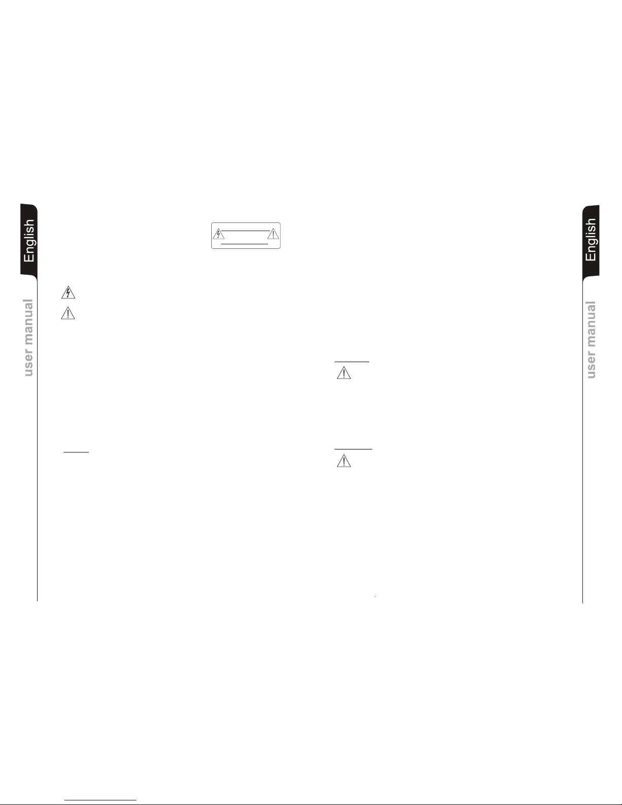
“CAUTION”
TO PREVENT ELECTRICAL SHOCK
DO NOT REMOVE COVER
“AVIS”
RISQUE DE CHOCH ELECTRIQUE
NE PAS OUVRIR

DeutschDeutschDeutsch
BedienungsanleitungBedienungsanleitung
15
DeutschDeutschDeutsch
BedienungsanleitungBedienungsanleitung
16
MERKMALE
Kühlung
Die Kühlung des Verstärkers erfolgt durch die Aluminiumplatte an der Rückseite des
Lautsprechers.
Der Hitzeschutz ist durch einen internen Schaltkreis gewährleistet, der die Temperatur des
Verstärkers überwacht und diesen vor Überhitzung schützt, indem die generelle
Lautstärke begrenzt wird ( bei Temperaturen >70°).
Wenn die Temperatur den maximalen Betriebswert erreicht (>80°), wird das Audiosignal
auf „mute“ gesetzt, was durch das Aufleuchten der gelben Kontrolllampe „MUTE“
angezeigt wird.
Die volle Lautstärke und sämtliche Funktionen werden automatisch wieder aufgenommen,
sobald die normale Betriebstemperatur wieder erreicht wird.
Schutz
Das Aufleuchten der gelben Kontrolllampe “MUTE” bedeutet, dass der Verstärker eine
Funktionsstörung des Lautsprechers festgestellt und diesen daher in den Mute- Zustand
versetzt hat.
In diesem Fall ist folgendes zu überprüfen:
- Den korrektenAnschluss an das Stromnetz kontrollieren
-Sicher stellen, dass die richtige Versorgungsspannung vorliegt
- Kontrollieren, dass der Verstärker nicht überhitzt ist.
- Den Lautsprecher vom Stromnetz trennen, einige Minuten abwarten und ihn dann
nochmals anschließen.
Wenn die Kontrolllampe auch nach dieser Wartezeit nicht erlischt, bitte eine qualifizierte
Kundendienststelle kontaktieren.
ANSCHLÜSSE
Netzanschluss
Jeder Aktivlautsprecher hat ein eigenes Netzkabel. Der Anschluss erfolgt mit einem
Netzstecker Neutrik POWER CON® (blau), der den einfachen und schnellen Anschluss
des Lautsprechers erlaubt und eine sichere Verriegelung garantiert. Der Stecker dient
zugleich als Schalter zum Einschalten undAusschalten der Lautsprecher.
Das Gerät muss an ein Netz angeschlossen werden, dass die verlangte maximale
Leistung abgeben kann.
Power-Weiterführung
Auf der Rückseite des Lautsprechers befindet sich eine Einbaukupplung Neutrik POWER
CON® (grau) für die Weiterleitung der Netzstromversorgung.
Über diese Steckbuchse kann man einen anderen Lautsprecher anschließen, um die
Anzahl der direkten Netzanschlüsse zu reduzieren. Die maximale Stromaufnahme der
Verstärker ist auf ihrem Typenschild angegeben.
Die Anzahl, der maximal aneinander anschließbaren Lautsprecher ist abhängig von ihrer
maximalen Stromaufnahme und vom maximalem Bemessungsstrom der ersten
Netzsteckdose.
VORSICHT
Hängen Sie den Lautsprecher nie an den Griffen auf!
BESCHREIBUNG
®-
Die Lautsprecher der “SUB D” Serie sind mit Class-D -Verstärkern aus der DIGIPRO
Serie ausgestattet. Dieser Hochleistungsverstärker ermöglicht eine hohe
Ausgangsleistungen bei geringstem Gewicht und kompakten Abmessungen. Dank der
sehr geringen Verlustleistung erfolgt die Kühlung des Verstärkermoduls durch Konvektion,
ohne Einsatz eines Lüfters.
Die Versorgungsspannung des SUB 18D wurde für den Vollbereichs-Betrieb ausgelegt.
Dank der SMPS- Technologie (Switched-Mode Power Supplies) mit PFC (Power Factor
Correction) wird der Arbeitsbereich bei Versorgungsspannungen zwischen 100V AC und
240V AC gewährleistet, wobei die gleichen Ausgangsleistungen auch bei schwankenden
und nicht stabilisierten Versorgungsleitungen garantiert sind.
Die Versorgungsspannung des SUB 15D ist für den Mehrbereich-Betrieb ausgelegt.
Wählbar in den Bereichen von 100- 120V, oder von 220 -240 V. Das Netzteil arbeitet
ebenfalls mit der SMPS- Technologie.
“SUB D” ist eine Serie von aktiven Subwoofern mit Holzgehäusen, die für die Beschallung
von mittelgroßen bis großen Räumen hergestellt wurden.
Als Bandpass-Subwoofer bietet der SUB D trotz seiner kompakten Abmessungen einen
beachtlich hohen Schalldruck.
Zur einfachen Anwendung, Installation und Transport, sind alle Subwoofer ausgestattet
mit:
-Seitlichen Griffen
-M20 Hochständerflansch
-Einfräsungen auf der Oberseite um das Aufstellen von FLEXSYS Topteilen oder
eines weiteren Subwoofers zu erleichtern.
-Räder Prädisposition (nur SUB 18D)
Die aktiven Subwoofer sind sowohl für den Stereobetrieb und Monobetrieb konzipiert. Die
Trennfrequenz kann entwerde zu 90 Hz oder 120 Hz gewählt werden, ebenso die Phase
entweder zu 0° oder 180°. Das Ausgangssignal der XLR- Buchse kann als LINK oder X-
OVER gewählt werden.
INSTALLATION DES LAUTSPRECHERS
ACHTUNG
Den Lautsprecher auf eine stabile und sichere Art und Weise installieren, um jede
Gefahr für Personen oder Sachschäden zu vermeiden.
Um gefährliche Situationen zu vermeiden, nie mehrere Lautsprecher ohne angemessene
Abspannsysteme aneinander anschließen.
Bei Verwendung im Freien sollte man darauf achten, das die Lautsprecher vor
witterungseinflüssen wie Sturm, Regen, Hagel, Schnee, usw. geschützt sind.
Aus Sicherheitsgründen, sollten sie beim über einander stellen von Subwoofern darauf
achten, dass diese nicht verrutschen oder umfallen können. Das Gehäuse ist mit einem
M20 Hochständerflansch ausgestattet zurAufnahme von Distanzstangen

DeutschDeutschDeutsch
BedienungsanleitungBedienungsanleitung
17
DeutschDeutschDeutsch
BedienungsanleitungBedienungsanleitung
18
BEDIENELEMENTE UND FUNKTIONEN
1) EINGANGSBUCHSE "BALANCED INPUT1” UND "BALANCED INPUT 2”
Symmetrischer XLR Eingang für Line-Pegel.
2) AUSGANGSBUCHSE "OUT 1” UND "OUT 2”
Zur Weiterleitung des Signals an weitere Lautsprecher. Das Signal kann als LINK/X-
OVER gewählt werden. Siehe (10).
3) LED “LIMITER”
Diese rote LED leuchtet auf, um das Ansprechen der Limiterschaltung zu
signalisieren, welche die Verzerrung des Verstärkers verhindert und die Lautsprecher
gegen Überlastung schützt.
4) LED “SIGNAL”
Diese LED leuchtet grün, wenn dasAudiosignal anliegt (mit einem Pegel von -20dB).
5) LED “MUTE”
Diese gelbe LED zeigt den Zustand “MUTE” des Verstärkers an.
Während des normalen Betriebs ist die LED ausgeschaltet.
6) LED “READY”
Diese LED leuchtet grün, wenn das Gerät an die richtige Netzspannung
angeschlossen ist. Während des normalen Betriebs leuchtet die LED.
7) EMPFINDLICHKEITSREGLER EINGANG “INPUT SENS”
Dieser Regler dient zum Einstellen der Eingangs-Empfindlichkeit des Verstärkers für
den Subwoofer. Diese Einstellung beeinflusst nicht den Ausgangspegel der Buchsen
"OUT 1” U ND " OUT 2” .
8) WAHLSCHALTER “PHASE”
Der Schalter dreht die Phase um 180°.
Durch das Drehen der Phase kann man die Wiedergabe der Bässe auch bei
ungünstigen akustischen Bedingungen in einfacher Weise optimieren. Nach
Abschluss der Installation ein Musikstück abspielen und ausprobieren, in welcher
Schaltstellung die tiefen Frequenzen am besten klingen.
9) WAHLSCHALTER FÜR DIE CROSSOVER-FREQUENZ “X-OVER”
Der Wahlschalter mit zwei Schaltstellungen dient zur Wahl der Crossover-Frequenz
zwischen dem Subwoofer und den Lautsprechern amAusgangs X-OVER.
Die Wahl der Trennfrequenz sollte vom Lautsprechertyp abhängig gemacht werden,
der für die Wiedergabe der mittleren und hohen Frequenz verwendet wird.
Bei 12” Lautsprechern empfiehlt sich die Trennfrequenz 120 Hz und bei 15”-
Lautsprechern die Trennfrequenz 90 Hz.
10) WAHLSCHALTER “MODE”
Er konfiguriert, welches Signal an den Buchsen OUT 1 und 2 ausgegeben werden
soll: In der Stellung “LINK” wird das Eingangs-Signal der Buchsen (1) parallel
abgegriffen . Nun können z.B. Weitere Subwoofer angeschlossen werden.
In der Stellung “X-OVER” wird der Hochpass der aktiven Frequenzweiche “X-
OVER” ausgegeben zumAnschluss der Satellitenlautsprecher.
11) EINBAUKUPPLUNG “MAINS INPUT”
Für denAnschluss des Netzkabels.
Für den Netzanschluss wird ein POWER CON® (blau) Einbaukupplung verw en det.
12) EINBAUKUPPLUNG FÜR DIE POWER-WEITERLEITUNG “MAINS OUTPUT
LINK”
Er dient zum Durchschleifen der Netzspannung. Der Ausgang ist parallel an den
Eingang (11) angeschlossen und kann zur Versorgung eines weiteren aktiven
Lautsprechers verwendet werden.
Der Steckverbinder ist eine POWER CON® (grau) Einbaukupplung .
13) SICHERUNGSHALTER “MAINS FUSE”
Er enthält die Netzsicherung.
TECHNISCHE DATEN
SUB 15D SUB 18D
System Aktiv Aktiv
Verstärker typ Class D Class D
RMS Leistung 800W 1000W
Frequenzgang 40- 120 Hz ( -3d B) 35-120Hz (-3dB)
Crossover 90Hz - 120Hz Wählbare 90Hz - 120Hz Wählbare
24dB/oct 24dB/oct
Schalldruck (max SPL) 133dB 134dB
Komponenten 1x15” Woofer - 3” voice coil 1x18” Woofer - 4” v oic e co il
Empfindlich keit Eingang max - 3dB u max -3dBu
Impedanz Eingang Symmetrisch 20Kohm Symmetrisch 20Kohm
Unsymmetrisch 10Kohm Unsymmetrisch 10Koh
Netzspannung Inte rn Wä hlb ar e Vollbereich mit PFC
100-120Vac 50-60Hz 100-240Vac 50-60Hz
220-240Vac 50-60Hz
Gehäuseform Rec hte ck ig Re cht eck ig
Farbe Schwarz Schwarz
Abmessungen (Bx HxT ) 436x600x600mm 530x700x600mm
Gewicht 32Kg 44Kg
Ständerflansch M20 (aluminium) 2x M20 ( alu mi niu m)
Griffe 2 (1x p ro Se it e) 4 (2 x pr o Sei te )

Caracteristiques techniquesCaracteristiques techniques Français
20
INSTRUCTIONS DE SÉCURITÉ
IMPORTANT
Le présent manuel fait partie intégrante du produit et doit accompagner celui-ci même en cas de
passage de propriété afin de permettre au nouveau propriétaire de connaître les modalités
d'installation et d'utilisation ainsi que les avertissements relatifs à la sécurité.
L'installation et l'utilisation qui ne sont pas conformes avec les prescriptions et modalités contenues
dans ce manuel d'emploi dégage le producteur de toute responsabilité en cas de dommages à
personnes, choses et structures.
Lire les instructions suivantes
Toutes les instructions de sécurité et de fonctionnement doivent être lues et comprises avant de mettre
l'appareil en fonction.
Tenir compte de tous les avertissements
Tous les avertissements concernant l'appareil et les instructions de fonctionnement doivent être
fidèlement suivis.
Inutilisation prolongée de l'appareil
Dans le cas où l'on prévoit de ne pas utiliser l'appareil pendant une longue période, il convient de le
débrancher du réseau électrique, le replacer dans son emballage et le recouvrir afin qu'il ne soit pas
exposé à la poussière.
Pannes et réparations
En cas de panne de l'appareil, il est absolument interdit pour l'utilisateur de tenter de le réparer ou de
retirer le couvercle de protection. Débrancher l'appareil du réseau d'alimentation et contacter
l'assistance technique pour la réparation.
PRECAUTIONS POUR L'INSTALLATION ET POUR L'UTILISATION
GENERALITES
Conserver les instructions
Pour une utilisation correcte de l'appareil, ce manuel d'instructions doit être maintenu avec soin pour
qu'il puisse être consulté ultérieurement.
Positionnement de l'appareil
Placer l'appareil en position stable et sûre de manière à éviter des situations de danger à choses,
personnes ou structures.
Mise à la terre de protection
L'appareil est réalisé en Classe I de protection contre la secousse électrique et le raccordement au
réseau électrique doit être fait à une prise dotée de conducteur de terre de protection. Avant d'effectuer
la connexion électrique de l'appareil, s'assurer que le système de distribution soit conforme aux
normes en vigueur en matière d'installations électriques.
Alimentation
L'appareil doit être branché à une source d'alimentation du type et dotée des caractéristiques
indiquées sur la plaque de l'appareil et spécifiées dans le présent manuel (Voir spécifications
techniques). Avant de brancher la fiche d'alimentation, s'assurer que la tension soit du type requis par
l'appareil.
Câble d'alimentation
Afin de garantir la sécurité d'utilisation de l'appareil, utiliser exclusivement le câble d'alimentation
fourni en ayant soin de le positionner et de le protéger pour ne pas l'endommager pendant l'utilisation.
En cas d'endommagement, contacter l'assistance technique et demande à ce qu'il soit changé. Ne pas
utiliser de câbles autres que ceux fournis.
AVERTISSEMENTS: AFIN DE LIMITER LES RISQUES DE DÉCHARGE
ÉLECTRIQUE NE PAS ENLEVER LE COUVERCLE (OU
LE PANNEAU ARRIÈRE). LES COMPOSANTS
INTERNES NE PEUVENT PAS ÊTRE RÉPARÉS PAR
L'UTILISATEUR; CONFIER LES RÉPARATIONS À DU
PERSONNELQU A L I F IÉ.
ATTENTION: AFIN DE RÉDUIRE LES RISQUES D'INCENDIE OU DE
DÉCHARGE ÉLECTRIQUE, NE PAS EXPOSER CET
APPAREIL À LA PLUIE OU À L'HUMIDITÉ.
Ce symbole a la fonction de signaler à l'utilisateur, là où il est apposé, la présence de tension
dangereuse à l'intérieur du produit, avec une valeur suffisante pour représenter un risque de
décharge électrique pour les personnes.
Ce symbole, là où il est reporté, a la fonction de signaler à l'utilisateur la présence d'instructions
d'utilisation et entretien (assistance) importantes dans la documentation qui accompagne
l'appareil.
“CAUTION”
TO PREVENT ELECTRICAL SHOCK
DO NOT REMOVE COVER
“AVIS”
RISQUE DE CHOCH ELECTRIQUE
NE PAS OUVRIR
Eau et humidité
L'appareil ne doit pas être installer à proximité de zones avec une présence de liquides ( ex. lavabos,
douches, baignoires, bords piscines, sols mouillés ou dans d'autres positions en présence d'eau et
liquides en général).
Pénétration d'objets et de liquides
L'appareil doit être positionné dans un lieu approprié. Eviter de positionner des objets et récipients de
liquides sur l'appareil, un renversement accidentel pourrait en causer l'intrusion à l'intérieur des grilles
de refroidissement avec, comme conséquence, un danger électrique.
Ventilation
Installer l'appareil dans une position ou zone adéquate de manière à garantir une recirculation d'air.
Ne pas obstruer ou couvrir les fentes d'aération et de ventilation ou les dissipateurs de l'appareil. Il
convient d'installer l'appareil à une distance qui assure une bonne ventilation entre les appareils.
Sources de chaleur
Ne pas installer ou utiliser l'appareil à proximité de sources de chaleur.
Accessoires et options
Il est absolument interdit de perforer le boîtier de l'appareil ou de fixer toute autre type de support
mécanique au moyen d'un adhésif. Dans le cas d'installations particulières et, dans tous les cas, non
décrites dans le présent manuel, contacter le service technique pour la liste des accessoires
disponibles pour l'appareil.
Suivre toutes les instructions
Toutes les instructions contenues dans ce manuel doivent être suivies pour une bonne utilisation et
un fonctionnement correct de l'appareil. L'attention est particulièrement attirée sur le fait de :
-Ne pas forcer les organes de commande (touches, contrôles, etc.).
-Eviter de faire travailler l'appareil en surcharge pendant longtemps.
Nettoyage
Nettoyer avec un chiffon sec. Pour le nettoyage des parties extérieures, éviter l'utilisation de diluants,
alcool, benzine ou autres substances volatiles.
BRANCHEMENTS
ATTENTION
-Pour brancher l’enceinte, adressez-vous à un spécialiste bien formé, c’est-à-dire à une
personne ayant de l’expérience ou des connaissances techniques ou ayant reçu des
instructions spécifiques qui lui permettent de réaliser correctement les connexions et de
prévenir les dangers de l’électricité.
-Pour éviter les risques de chocs électriques, terminez toutes les connexions avant de
brancher l’enceinte sur le secteur.
- Avant d’alimenter l’enceinte, il est de bonne règle de re-contrôler toutes les connexions et de
s’assurer en particulier qu’il n’y a pas de courts-circuits accidentels.
- Tout le système de sonorisation devra être réalisé conformément aux normes et aux lois en
vigueur en matière d’instal-lations électriques.
SUGGESTIONS
ATTENTION
Pour éviter que des phénomènes inductifs provoquent des bourdonnements, perturbent
et compromettent le bon fonctionnement de l’enceinte, blindez les fils qui transmettent
des signaux microphoniques ou des signaux au niveau de la ligne (0 dB/V) et évitez de les
poser à proximité de :
1) appareils produisant de forts champs magnétiques (gros transformateurs
d’alimentation) ;
2) conducteurs de l’énergie électrique.
3) lignes qui alimentent les enceintes.
Français
Caracteristiques techniquesCaracteristiques techniques
19

Caracteristiques techniquesCaracteristiques techniques Français
22
Français
Caracteristiques techniquesCaracteristiques techniques
21
DESCRIPTION
Les diffuseurs de la série “SUB D” sont équipés d'un amplificateur en classe D de la série
®
DIGIPRO . Cet amplificateur, de très haute efficacité, permet d'obtenir des puissances de
sorties élevées avec des poids et encombrements réduits. Grâce à la basse puissance
dissipée, le refroidissement du module amplificateur se fait de manière statique évitant
l'utilisation de ventilateur.
Le circuit d'alimentation de l'amplificateur DIGIPRO® , monté sur SUB 15D diffuseur, a été
conçu pour travailler en fonction de tension d'alimentation et conçu avec la technologie
SMPS (Switched-Mode Power Supplies).
Le circuit d'alimentation de l'amplificateur DIGIPRO®, monté sur SUB 18D diffuseur, a été
conçu pour fonctionner en modalité full-range ; grâce à la technologie SMPS (Switched-
Mode Power Supplies) avec PFC (Power Factor Correction), le fonctionnement à tensions
d'alimentations de 100Vac à 240Vac, assurant les mêmes prestations acoustiques même
avec des lignes d'alimentation fluctuantes et non stabilisées.
“SUB D” est une série de diffuseurs actif en bois de bouleau, étudiés pour la sonorisation
des lieux moyennement grands.
L'enceinte SUB D est réalisée en utilisant la typologie “ BAND PASS ”, qui permet d'obtenir
des pressions acoustiques élevées avec des dimensions réduites.
Pour faciliter l’utilization, l’installation et le transport tous les woofer sont pourvus de:
- poignées latéraux
- support avec filet M20 pour hampe
- sièges pour appui de diffuseurs aux deux voies serie FLEXSYS ou autre subwoofer
dans la partie supérieure du box même
! prédisposition roues (uniquement SUB 18D)
Diffuseurs ont un sub-woofer actif conçu pour fonctionner en modalité stéréo ou en
modalité mono. Il est possible de configurer la fréquence de coupure (90Hz ou 120Hz) et
tournant de phase (0 ° ou 180 °). Les signaux de sortie pourrait être lié ou de contrôle par
XOVER sortie.
CARACTERISTIQUES
Refroidissement
Le refroidissement de l'amplificateur se fait au travers d'un panneau en aluminium situé
derrière le diffuseur.
La protection thermique est assurée par un circuit interne qui contrôle la température de
l'amplificateur et le protège contre la surchauffe limitant le volume général (avec
température >70°).
Si la température atteint celle maximum d'utilisation (>80°), le signal audio est placé en état
de “mute” et sera signalé par l'allumage du voyant lumineux jaune “MUTE”.
Le bon volume et toutes les fonctions seront reprises automatiquement quand les
températures normales de travail auront été atteintes.
Protection
L'allumage du voyant lumineux jaune “MUTE” indique que l'amplificateur a détecté un
disfonctionnement sur le diffuseur le plaçant en état de mute.
Effectuer les vérifications suivantes :
- Contrôler que le branchement au réseau d'alimentation soit correct.
-S'assurer que la tension d'alimentation soit correcte.
- Contrôler que l'amplificateur ne soit pas en surchauffe.
- Débrancher du réseau d'alimentation le diffuseur et attendre quelques minutes et
puis essayer à nouveau
Si après ces tests, le voyant ne s'éteint pas, contacter un centre d'assistance autorisé.
BRANCHEMENTS
Branchement au réseau d'alimentation
Chaque enceinte active est dotée de son cordon d'alimentation. Le branchement
s'effectue au moyen d'un connecteur modèle Neutrik POWER CON® (bleu) qui rend aisé
et rapide le branchement de l'enceinte et assure un excellent blocage.
Le même connecteur sert de passage à allumer et éteindre le haut-parleur.
L'appareil doit être branché à un réseau d'alimentation en mesure de fournir la puissance
maximum requise.
Relance alimentation de réseau
À l'arrière de l'enceinte, on trouve un connecteur Neutrik POWER CON® (gris) pour la
relance de l'alimentation de réseau.
Cette prise sert pour relancer l'alimentation à une autre enceinte et réduire ainsi les
branchements directs au réseau. Les absorptions maximums des amplificateurs sont
reportées sur la façade de l'amplificateur.
Le nombre maximum d'enceintes pouvant être reliées varie aussi bien en fonction des
absorptions maximums des enceintes que du courant maximum de la première prise
d'alimentation.
IINSTALLATION DU DIFFUSEUR
ATTENTION
Installer le diffuseur de façon stable et sûre afin d'éviter toute condition de danger
pour l'intégrité des personnes et des structures.
Afin d'éviter les conditions de danger, ne pas superposer entre eux plusieurs diffuseurs
sans systèmes d'ancrage appropriés.
Lors de l'utilisation en espace aérés, éviter les lieux exposés aux intempéries.
Le diffuseur est fourni par l'entreprise qui le fabrique et il est prédisposé pour l'utilisation en
appui
ATTENTION
Ne jamais utiliser les poignées pour suspendre l'enceinte!

Caracteristiques techniquesCaracteristiques techniques Français
24
Français
Caracteristiques techniquesCaracteristiques techniques
23
COMMANDES ET FONCTIONS
1) CONNECTEURS D'ENTRÉE “BALANCED INPUT 1” ET “BALANCED INPUT 2”
Entrées symétriques au niveau ligne.Accepter "XLR" prises de courant.
2) CONNECTEURS DE SORTIE “OUT 1” ET “OUT 2”
Le "XLR" connecteurs peut être pour envoyer le signal audio d'entrée d'une autre
enceinte amplifiée.
Le signal est de choisir entre “LINK / X-OVER" (10) sélecteur
3) INDICATEUR LUMINEUX “LIMITER”
Cet indicateur s'allume de couleur rouge pour indiquer l'intervention du circuit
limiteur interne qui évite la distorsion de l'amplificateur et protège les haut-parleurs
contre les surcharges
4) INDICATEUR LUMINEUX “SIGNAL”
Cet indicateur s'allume de couleur verte pour indiquer la présence du signal audio (à
un niveau de -20dB).
5) INDICATEUR LUMINEUX “MUTE”
Cet indicateur de couleur jaune indique l'état de l'amplificateur.
Pendant le fonctionnement normal, la LED est éteinte
6) INDICATEUR LUMINEUX “READY”
Cet indicateur s'allume de couleur verte pour indiquer que la tension d'alimentation
de réseau est correcte. Pendant le fonctionnement normal, la LED est allumée.
7) CONTRÔLE SENSIBILITÉ ENTRÉE “INPUT SENS”
Ce contrôle règle la sensibilité du signal en entrée à l'amplificateur.
Ce contrôle n'influence pas le niveau de la sortie“OUT 1” ET“OUT 2”
8) SÉLECTEUR “PHASE”
Le sélecteur à deux positions permet la rotation de 180° du signal audio reproduit par
le caisson de grave.
Cette rotation de phase facilite l'optimisation de la reproduction des basses
fréquences même dans les conditions d'installation les plus difficiles. Une fois
l'installation terminée, reproduire un morceau de musique et agir sur l'interrupteur
afin d'obtenir la meilleure restitution acoustique des basses fréquences.
9) SÉLECTEUR DE FRÉQUENCE DE CROISEMENT “XOVER”
Le sélecteur permet de sélectionner la fréquence de croisement
entre le caisson de grave et les enceintes connectées aux sorties XOVER.
Le choix de la coupure est lié au type d'enceinte que l'on utilise pour la reproduction
des moyennes-hautes fréquences.
Avec des enceintes équipées de cônes de 12”, il est conseillé d'utiliser la coupure à
120Hz; tandis que, avec des enceintes de 15”, il est conseillé d'utiliser 90Hz.
10) SÉLECTER "X-OVER"
Cet interrupteur permet de sélectionner le type de signal à envoyer "OUT 1" et "OUT
2" sorties.
La position “FLAT” permet de lier le même signal d'entrée.
La position "XOVER" permet d'envoyer de signal d'entrée en fonction de fréquence
de coupure de sélectionnés par "XOVER" switch.
11) PRISE D'ALIMENTATION “MAINS INPUT”
Elle permet de connecter le cordon d'alimentation fourni.
Le connecteur utilisé pour le branchement au réseau est du type POWER CON®
(bleu)
12) PRISE D'ALIMENTATION RELANCE “MAINS OUTPUT LINK”
Elle permet de relancer l'alimentation de réseau. La sortie est branchée en parallèle
avec l'entrée (11) et peut être utilisée pour alimenter une autre enceinte amplifiée.
Le connecteur utilisé est du type POWER CON® (gris)
13) BLOC À FUSIBLE “MAINS FUSE”
Logement pour le fusible de réseau.
DONNES TECHINIQUES
SUB 15D SUB 18D
Système
Typologie amplificateur Class D Class D
Puissance RMS 800W 1000W
40 -12 0H z (-3 dB) 35-120Hz (-3dB)
Crossover 90Hz - 120Hz sé lec tio nna bl e 90Hz - 120Hz séle ct ion nab le
24dB/oct 24dB/oct
Pression sonore (max SPL) 133dB 134dB
Composantes 1x15” woo fer - 3 ” vo ice c oil 1x18” woofer - 4” v oic e coi l
Entrée sensibilité max -3d Bu max -3dBu
Impedance entrée Sym étr iq ue 20 Koh m Symétrique 20K ohm
Asymétrique 10Kohm Asymétrique 10Kohm
Alimentation séle cti onn ab le ìn ter nam én t Full-range con PFC
100-120Vac 50-60Hz 100-240Vac 50-60Hz
220-2400Vac 50-60Hz
Forme enceinte Rec tan gu lai re Re cta ng ula ire
Couleurpeinture Noir Noir
Dimensions (WxHxD) 436x600x600mm 530x700x600mm
Poids 32Kg 44Kg
Stand support M20 2x M20
Poignée 2 (1x de chaque côté) 4 (2x de chaque côté)
Active Active
(a lum in ium ) (al umi niu m)
Réponse en fréquence

25
12
PUSH
ON MUTE SGN LIM
PHASE
90Hz
8
0dB
Mono
OUT 1 OUT 2
120Hz 0°
180°
XOVER
SUB-WOOFER
LEVEL
LINK
XOVER
BALANCED
INPUT 1
MONO
BALANCED
INPUT 2
0dB
Stereo
PUSH
8
7
6
5
4
3
1
2
9
10
SUB 15DSUB 15D
11
13 12
MAINS LINK
ACTIVE P.F.C.
MAINS
FUSE
FULL RANGE MAINS INPUT
100-240V~50-60Hz
1000W MAX
OUTPUT
220-240V~ MAX 15A
100-120V~ MAX 10A
220-240V~ (T5A 250V)
100-120V~ (T10A 250V)
“CAUTION”
TOPREVENT ELECTRICAL SHOCK
DONOT REMOVE COVER
“AVIS”
RISQUEDE CHOCH ELECTRIQUE
NEPAS OUVRIR
PUSH
ON MUTE SGN LIM
PHASE
90Hz
8
0dB
Mono
OUT 1 OUT 2
120Hz 0°
180°
XOVER
SUB-WOOFER
LEVEL
LINK
XOVER
BALANCED
INPUT 1
MONO
BALANCED
INPUT 2
0dB
Stereo
PUSH
8
7
6
5
4
3
1
2
9
10
11
13
SUB 18DSUB 18D
“CAUTION”
TOPREVENT ELECTRICAL SHOCK
DONOT REMOVE COVER
“AVIS”
RISQUEDE CHOCH ELECTRIQUE
NEPAS OUVRIR
LINK
MAINS INPUT
MAINS FUSE
O
N
F
F
O
O
N
F
F
O
OUTPUT
100-120V~ MAX 12A
220-240V~ MAX 16A
100-120V~ 50-60Hz
220-240V~ 50-60Hz
(T8A 250V~)
(T4A 250V~)
Internal voltage setup
MODULE POWER
CONSUMPTION
800W MAX
26

SCHEMA A BLOCCHI / BLOCK DIAGRAM
BLOCKSCHALTBILD / SCHEMAS FONCTIONNELS
28
27
DIMENSIONI / DIMENSIONS
ABMESSUNGEN / DIMENSIONS
436436
600600
600600
600600
700700
530530
SUB 18D
SUB 15D
WOOFER 15”
BALANCED
CH2 INPUT
LINK
L
N
MAINS INPUT
Switching Mode
Power Supply
SMPS
MAINS
FUSE
L
N
MAINS OUTPUT
LINK
XOVER FREQ
uPROCESSOR
XOVER
Class D
SUB 15D
®
DIGIPRO
XOVER
LIMITER
M
VOLUE
BALANCED
CH1 INPUT
LINK
XOVER FREQ
XOVER
XOVER
BALANCED
CH1 OUT
BALANCED
CH2 OUT
PFC
Power Factor
Correction
PSE
HA
WOOFER 18”
BALANCED
CH2 INPUT
LINK
L
N
FULL RANGE
MAINS INPUT
Switching Mode
Power Supply
SMPS
MAINS
FUSE
MAINS OUTPUT
LINK
XOVER FREQ
uPROCESSOR
XOVER
Class D
SUB 18D
®
DIGIPRO
XOVER
LIMITER
VOUMEL
BALANCED
CH1 INPUT
LINK
XOVER FREQ
XOVER
XOVER
BALANCED
CH1 OUT
BALANCED
CH2 OUT
PHSE
A
Class D
L
N
LIMITER
SIGNAL
MUTE
READY
LIMITER
SIGNAL
MUTE
READY

CONFIGURAZIONI e
CONFIGURATION and
KONFIGURATIONEN und
CONFIGURATIONS et
COLLEGAMENTI
CABLE CONNECTIONS
VERKABELUNG
CABLAGE
MONO
MIXER
MIXER
PUSH
ON MUTE SGN LIM
PHASE
90Hz
8
0dB
Mono
OUT 1 OUT 2
120Hz 0°
180°
XOVER
SUB-WOOFER
LEVEL
LINK
XOVER
BALANCED
INPUT 1
MONO
BALANCED
INPUT 2
0dB
Stereo
PUSH
MIXER
ACTIVE SUBWOOFER
MIXER
PUSH
ON MUTE SGN LIM
PHASE
90Hz
8
0dB
Mono
OUT 1 OUT 2
120Hz 0°
180°
XOVER
SUB-WOOFER
LEVEL
LINK
XOVER
BALANCED
INPUT 1
MONO
BALANCED
INPUT 2
0dB
Stereo
PUSH
STEREO
MONO
MIXER MIXER
MIXER
PUSH
ON MUTE SGN LIM
PHASE
90Hz
8
0dB
Mono
OUT 1 OUT 2
120Hz 0°
180°
XOVER
SUB-WOOFER
LEVEL
LINK
XOVER
BALANCED
INPUT 1
MONO
BALANCED
INPUT 2
0dB
Stereo
PUSH
ACTIVE SPEAKER
MIXERMIXER
ACTIVE SPEAKER
ACTIVE SPEAKER
READY
MUTE
SIGNAL
LIMITER
SENSITIVITY
0dB
8
+4dB
MODE
-3dB
BALANCED
INPUT
LINK
OUT
PUSH
MIXER
READY
MUTE
SIGNAL
LIMITER
SENSITIVITY
0dB
8
+4dB
MODE
-3dB
BALANCED
INPUT
LINK
OUT
PUSH
READY
MUTE
SIGNAL
LIMITER
SENSITIVITY
0dB
8
+4dB
MODE
-3dB
BALANCED
INPUT
LINK
OUT
PUSH
PUSH
ON MUTE SGN LIM
PHASE
90Hz
8
0dB
Mono
OUT 1 OUT 2
120Hz 0°
180°
XOVER
SUB-WOOFER
LEVEL
LINK
XOVER
BALANCED
INPUT 1
MONO
BALANCED
INPUT 2
0dB
Stereo
PUSH
PUSH
ON MUTE SGN LIM
PHASE
90Hz
8
0dB
Mono
OUT 1 OUT 2
120Hz 0°
180°
XOVER
SUB-WOOFER
LEVEL
LINK
XOVER
BALANCED
INPUT 1
MONO
BALANCED
INPUT 2
0dB
Stereo
PUSH
PUSH
ON MUTE SGN LIM
PHASE
90Hz
8
0dB
Mono
OUT 1 OUT 2
120Hz 0°
180°
XOVER
SUB-WOOFER
LEVEL
LINK
XOVER
BALANCED
INPUT 1
MONO
BALANCED
INPUT 2
0dB
Stereo
PUSH
ACTIVE SPEAKER
READY
MUTE
SIGNAL
LIMITER
SENSITIVITY
0dB
8
+4dB
MODE
-3dB
BALANCED
INPUT
LINK
OUT
PUSH
ACTIVE SUBWOOFER
ACTIVE SUBWOOFER
MONO
LINK
XOVER LINK
XOVER
LINK
XOVER
LINK
XOVER
LINK
XOVER
ACTIVE SUBWOOFER
ACTIVE SUBWOOFER ACTIVE SUBWOOFER
30
29
CONFIGURAZIONI e
CONFIGURATION and
KONFIGURATIONEN und
CONFIGURATIONS et
COLLEGAMENTI
CABLE CONNECTIONS
VERKABELUNG
CABLAGE

Set di 4 ruote - opzione DWK 20
Set of 4 wheels - DWK 20 option
SOLO CON SUB 18D
ONLY WITH SUB 18D
31 32
Table of contents
Languages:
Other AEB Subwoofer manuals