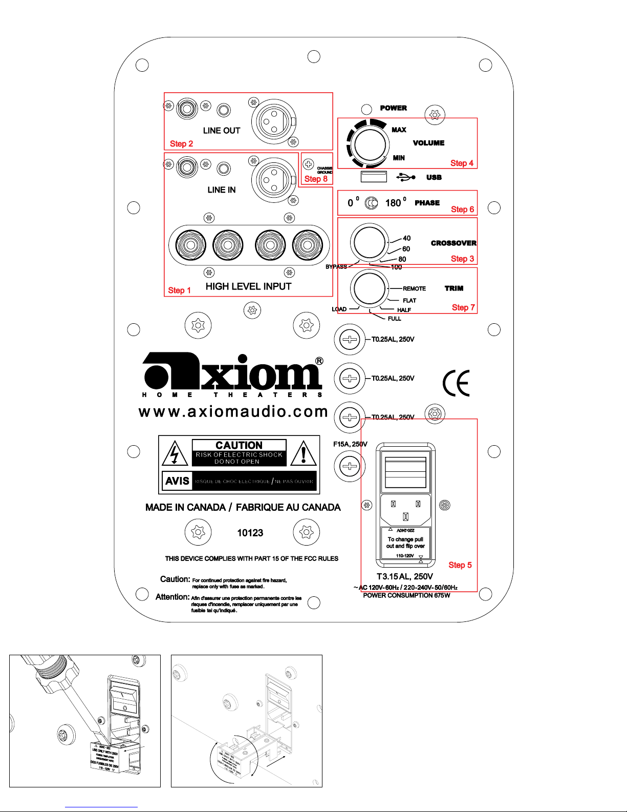
EP400 - ELECTRICAL CONNECTIONS
Step 1:
LINE IN: The RCA line-level female input, second row, accepts a standard
RCA male plug. Connect a shielded coaxial cable, with male RCA plugs on
eachend,fromtheA/VreceiverorA/Vpreampprocessor’sSubwooferOutput
jack to the RCA LINE IN female jack on the EP400.
3.5mm MINI-Jack: This is for any 3-Volt to 30-Volt power-on trigger. It is also
intended for trigger-controlled operation with future Axiom products.
BALANCED XLR LINE IN: If the A/V receiver or A/V preamp-processor has
balanced XLR subwoofer line-out connections, you may connect a Balanced
XLR male connector to the XLR female input. Otherwise, ignore this connector.
Do not use a combination of RCA and XLR input or output connectors.
HIGH LEVEL INPUT: Use these “speaker-level” or high-level 5-way binding
post connectors only if your receiver or preamp lacks a dedicated line-level
subwoofer output jack. Connect speaker cables from your amplier’s left-
channel and right-channel speaker output binding posts to the high-level
inputsusingbananaplugs(singleordual),spadeconnectors,pins,orbare
cable if you wish (unscrew the top of each binding post and insert the cable
intotheholeinthepost;tightentheknurledknobagainstthecable).Runa
second pair of speaker cables from these jacks to your main left and right
front speakers. Do not use these connectors if you are already using an RCA
or XLR line-level connection from the receiver or preamp to the subwoofer.
NOTE: BE SURE TO CONNECT BLACK TO BLACK AND RED TO RED.
Step 2:
LINE OUT (RCA, Trigger and XLR Balanced):
An RCA line-level (female) output and balanced XLR output (male) are
provided for connection to a second subwoofer. Use a standard shielded
coaxial cable for connection of the RCA Line Out to the second subwoofer. If
you are using balanced XLR connectors, then use the balanced Line Out for
operation of a second EP400.
Step 3:
CROSSOVER: If you are using the Bass Management crossover menu
settings in your A/V receiver or processor, turn the subwoofer crossover
control to the setting at or just above the highest crossover point you selected
on your AV receiver menu, i.e. for a 90-Hz or higher receiver menu setting,
use“Bypass”onthesub(“Bypass”selectsa150-Hzcrossover),for70–80
HzontheAVreceiver’smenu,use80Hzonthesub,andsoon.Ifyourleft
and right front satellite speakers have a woofer diameter of 4 inches or less,
use the 150-Hz “Bypass” setting on your subwoofer to enable a smoother
transition between your subwoofer and satellites.
IfyouareusingtheHIGHLEVEL (Speaker Level) binding-post inputs, set
thesubwoofercrossoverswitchto80Hzforinitialsetup.Ifyouhaveoor-
standingspeakers(M50,M60,orM80),trya60Hzcrossoverfrequency,for
theM80try40Hz.Ifyourmainspeakersarebookshelfmodelsusethe80Hz
setting. Ultimately you want to use a crossover frequency that produces the
smoothest blend of sound between the subwoofer and your main speakers.
Step 4:
VOLUME:Setthevolumetothe9o’clockpositionforthetimebeing.Later,
whenyouhavenishedthehookupofyoursubwoofer,youwillreturntothis
volume setting to balance the output of the subwoofer to the other speakers.
Avoid the use of the auto-setup feature in your receiver if it is equipped with
one. These devices rarely work properly. The best method is to balance your
sub to the other speakers using a variety of music you are very familiar with.
Settingupsublevelsandpropersubplacementinyourroomcanbetrickybut
worthputtingsomeeffortintoastheresultswillbesignicant.Foradetailed
description please go to www.axiomaudio.com/archives/subsetup.html
Step 5:
ON/OFF AC POWER/VOLTAGE SETTING: Your subwoofer is supplied with
a pop-out voltage regulator set for use with 100 - 120 volts from the A/C line.
It can be easily removed and turned over to set your EP400 to 220 volts from
theA/Cline.Seediagramsonthenextpage.TheEP400comewithathree-
prongpowercordcompatiblethroughouttheUnitedStatesandCanada.Other
International countries will need to purchase a converter/adaptor or the proper
powercordthattsyourspecicsocket.
Once you have made appropriate connections from the A/V receiver or
preamp/processor to the EP400 and set the subwoofer’s voltage regulator
to the proper voltage, nd a nearbyAC wall outlet and connect the main
power cord to the three-wire socket at the bottom of the control panel. Move
the power switch to the ON setting. The LED POWER indicator should glow
Green. Leave the switch at the ON setting unless you go away for an extended
period. Moving it to OFF will shut down all power to the subwoofer.
Step 6:
0 & 180 PHASE: This synchronizes the in/out movement of the subwoofer
cone driver with the other speakers in your system. Once you have chosen
thebestlocationfor your subwoofer,tryipping the phase switch between
0and180toseeifoneortheothersettingproducesdeeperandsmoother
bass output in your room. Leave the switch at the setting that results in the
smoothest and deepest bass at several listening locations in the room. If you
hear no difference, leave the switch at the 0 position. Quite often the phase
switch makes no difference, but it’s dependent on your particular room’s
dimensions and subwoofer location.
Step 7:
TRIM: Set this to FLAT for normal subwoofer operation in a large room.
The subwoofer will reproduce deep bass at normal levels from the movie
soundtrack or music sources. The LOAD setting is for accessing the internal
microprocessor. Do not use this setting as it will turn off the sub output and
turn the light amber. The REMOTE setting is for operation with future Axiom
remote-controlled products that will enable remote-control adjustment of
subwoofer levels. If you are in a medium or small room you should experiment
withHalfandFulltocompensateforroomloading.SettingtheTRIMtoHalf
will partially increase frequencies above 33 Hz. The Full setting will greatly
increase frequencies above 33 Hz. This may be necessary to overcome room
loadingorboundaryeffects(toomuchortoolittlelowbass).
Step 8:
GROUND LOOP:
If your subwoofer is producing a 60 Hz hum, remove the Chassis Ground
Screw.Ifthisdoesnotsolvethe60Hzhum,call1-866-244-8796orconsult
the troubleshooting page at www.axiomaudio.com/manual_ep400.html
POWER INDICATOR: The LED Power indicator glows Green when it’s on and
Yellow indicating a fault.
USB: This is to be used for future software upgrades to the Digital Signal
ProcessorinsideyourEP400.YoumayalsousetheUSBinputtoconnect
the accessory Axiom light to ease visibility in making subwoofer adjustments
or connections. Visit www.axiomaudio.com/manual_index.html for full owners
manual.
Visit www.axiomaudio.com/manual_index.html for this Owner’s Manual with live links to further helpful information