AEB DVA S09DP User manual

A.E.B. INDUSTRIALE s.r.l.
Via Brodolini, 8 - 40056 Crespellano (Bo) - ITALIA
Tel. + 39 051 969870 - Fax. + 39 051 969725
Internet: www.dbtechnologies.com
E-mail: [email protected]
MANUALE D’USO
USER MANUAL
BEDIENUNGSANLEITUNG
CARACTERISTIQUES TECHNIQUES
Made in Italy
COD. 420120162A Rev 4.0
digital power
RR
SS
00
STEREO ACTIVE SUBWOOFER
ItalianoItalianoItaliano
Manuale d’usoManuale d’uso
2
1
ItalianoItalianoItaliano
Manuale d’usoManuale d’uso
DESCRIZIONE
Il diffusore DVA S09dp è un subwoofer attivo della serie DVA (Digital Vertical Array)
®
equipaggiatoconamplificatoreDIGIPRO 1000s.
Questo è un amplificatore in classe D, ad alta efficienza, che permete di ottenere elevate
potenze di uscita con pesi ed ingombri ridotti. Grazie alla bassa potenza dissipata il
raffreddamentodelmoduloamplificatoreavvieneinmodostatico,evitandol’usodiventola.
®
Il circuito di alimentazione dell’amplificatore DIGIPRO , montato sul diffusore DVAS09dp,
è stato progettato per funzionare in modalità full-range; grazie alla tecnologia SMPS
(Switched-Mode Power Supplies) con PFC (Power Factor Correction) viene garantito il
funzionamento a tensioni di alimentazioni da 100Vac a 240Vac, assicurando stesse
prestazioniacusticheancheconlineedialimentazionefluttuantienonstabilizzate.
Il diffusore DVA S09 dp è stato progettato per funzionare in modalità stereo o modalità
mono. E’ possibile settare la frequenza di incrocio (90Hz oppure 120Hz) e la rotazione di
fase (0° oppure 180°). I segnali di uscita possono essere link oppure pilotati dal circuito
XOVER.
Il DVA S09dp è realizzato in legno di betulla, studiato per sonorizzare ambienti di medie
dimensioni; è costruito utilizzando la tipologia “BAND PASS” che permette di ottenere alte
pressioniacusticheindimensioniridotte.
Perfacilitarel’utilizzo,l’installazioneeiltrasportoèprovvistodi:
- maniglielaterali(esclusoDVAS09dpBianco),
- supportoconfilettoM20perasta(esclusoDVAS09dpBianco),
- sediperappoggiodiunaltrosubwoofer,nellapartesuperioredelbox,
- predisposizioneperstaffeappendibilità,
- predisposizioneperruote(esclusoDVAS09dpBianco).
COLLEGAMENTI
Collegamentoallaalimentazionedirete
Ogni diffusore attivo è provvisto del proprio cavo di alimentazione. Il collegamento
avviene tramite un connettore modello Neutrik POWER CON® (blu) che permette di
avere una facile e rapita connessione al diffusore oltre che a un ottimo sistema di
bloccaggio.
Lostessoconnettoresvolgelafunzionediinterruttoredirete.
L’apparecchio dovrà essere collegato ad una rete di alimentazione che possa erogare la
massimapotenzarichiesta.
Rilancioalimentazionedirete
Sul retro del diffusore è presente un connettore Neutrik POWER CON® (grigio) per il
rilanciodell’alimentazionedirete.
Questa presa ha lo scopo di rilanciare l’alimentazione ad un altro diffusore riducendo i
collegamentidirettiallarete. Gliassorbimentimassimidegliamplificatori sonoriportatisul
pannellodell’amplificatore.
Il numero massimo dei diffusori collegati insieme varia sia per gli assorbimenti massimi
deidiffusoriesiadallacorrentemassimadellaprimapresadialimentazione.
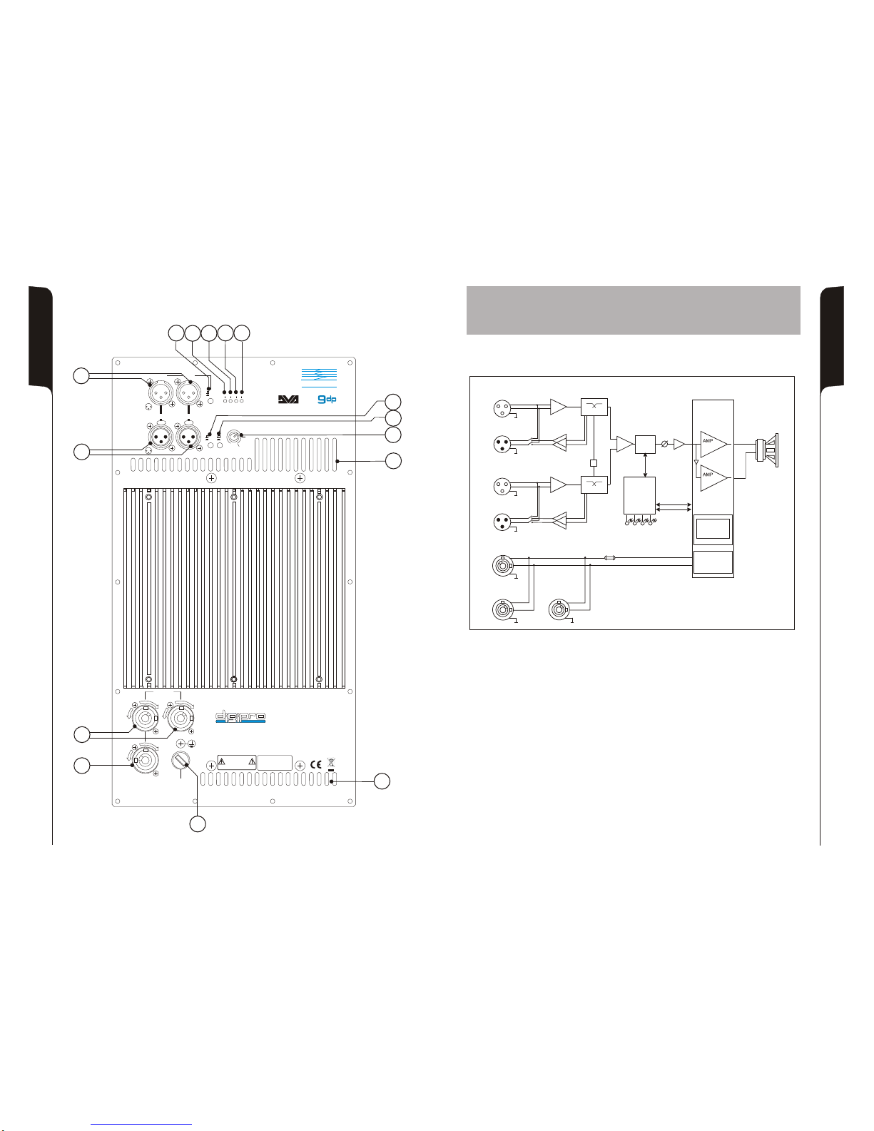
COMANDI E FUNZIONI (riferimento figura a pag.21)
1) CONNETTORI INGRESSO"BALANCEDINPUTS”“INPUT 1”e "INPUT2”
Connettori“XLR”diingressobilanciatoalivello linea.
2) CONNETTORIDIUSCITA“BALANCEDOUTPUTS”"OUT1”e "OUT2”
I connettori “XLR” sono utilizzati per inviare il segnale audio ad un altro diffusore
amplificato.
Iltipodisegnaleèselezionabiletramitel’interruttore”LINK/XOVER”(10)
3) INDICATORELUMINOSO“LIM”(LIMITER)
Questo indicatore s’illumina di colore rosso per indicare l'intervento del circuito
limitatore interno, il quale evita la distorsione dell'amplificatore e protegge gli
altoparlantidasovraccarichi.
4) INDICATORELUMINOSO“SGN”(SIGNAL)
Questo indicatore s'illumina di colore verde per indicare la presenza del segnale
audio(adunlivellodi-20dB).
5) INDICATORELUMINOSO“MUTE”
Questoindicatoredicoloregialloindicalostatodell’amplificatore.
Nelnormalefunzionamentoilledèspento.
6) INDICATORELUMINOSO“ON”(READY)
Questo indicatore s'illumina di colore verde per indicare che la tensione di
alimentazionedireteècorretta.
Nelnormalefunzionamentoilledèacceso.
7) CONTROLLOSENSIBILITA’INGRESSO“SUB-WOOFERLEVEL”
Questocontrolloregolalasensibilitàdelsegnaleiningressoall’amplificatore.
Talecontrollononinfluiscesullivellodell’uscita“OUT1”e“OUT2”
8) SELETTORE“PHASE”
Questo interruttore a due posizioni permette la rotazione di 180°del segnale audio
riprodottodalsubwoofer.
La rotazione facilita l’ottimizzazione della riproduzione alle basse frequenze anche
nelle situazioni di installazioni difficili. Completata l’installazione, riprodurre un brano
musicale ed agire sull’interruttore per ottenere la migliore resa acustica alle basse
frequenze.
9) SELETTORE“XOVER”
Questo interruttore permette di selezionare la frequenza di incrocio tra subwoofer e i
diffusori collegati alle uscite “OUT 1” e “OUT 2”. La scelta del taglio è legata al tipo di
diffusorechesiutilizzaperlariproduzionedellefrequenzemedio-alte.
Peri diffusoricon i coni a 12” èconsigliabile utilizzare un taglio a 120Hz,mentre con i
diffusoriconconida15”usareuntaglioa90Hz.
10) SELETTORE“LINK/XOVER”
Questo interruttore permette di selezionare il segnale da rilanciare sulle uscite “OUT
1”e“OUT2”.
Laposizione“LINK”permettedirilanciarelostessosegnalediingresso.
La posizione “XOXER” permette d’ inviare il segnale di ingresso tagliato alla
frequenzadiincrocioselezionatatramiteilselettore“XOVER”(9)
11) PRESADIALIMENTAZIONE“MAINSINPUT”
Consente la connessione del cavo di alimentazione e svolge la funzione di
interruttoredirete.
IlconnettoreutilizzatoperilcollegamentoallareteèunPOWERCON® (blu)
12) PRESEDIALIMENTAZIONERILANCIO“MAINS LINK”
Consentonodi rilanciarel’alimentazionedirete.Le ’uscitesonoconnesse inparallelo
conl’ingresso(11)epossonoessereutilizzateperalimentarealtri diffusoriamplificati.
IconnettoriutilizzatisonoPOWERCON® (grigio).
13) PORTAFUSIBILE“MAINSFUSE”
Alloggioperfusibiledirete.
14) GRIGLIEDIRAFFREDDAMENTO
Queste griglie permettono il raffreddamento dell’amplificatore durante il
funzionamento. Non ostruire gli accessi e pulire le griglie quando necessita per
garantireilcorrettocircolodell’aria.

ItalianoItalianoItaliano
Manuale d’usoManuale d’uso
3
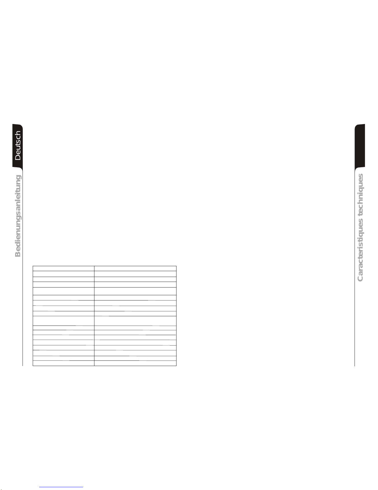
DATI TECNICI
Sistema Attivo
Tipologiaamplificatore ClasseD (DIGIPRO )
PotenzaRMS 1000W
Potenzamusicale 2000W
Rispostain frequenza 40-120Hz(-3dB)
38Hz-XOVER(-10dB)
Crossover 90Hz - 120Hz selezionabile , 24dB/oct
Pressionesonora (max SPL) 135dB
Componenti 1x15” woofer neodimio,4”voicecoil
Sensibilitàingresso max-3dBu
Impedenzaingresso Bilanciato 20Kohm
Sbilanciato 10Kohm
Alimentazione Full-rangeconPFC, 100-240Vac, 50-60Hz
Formadiffusore Rettangolare
Colorediffusore Nero
Dimensioni(WxHxD) 515x440x720mm
Peso 37,5Kg
Peso(constaffeper appendibità) 41,5Kg
Supportopiantana M20(alluminio)
Maniglie 4inmetallo (2per lato)
®
4
EnglishEnglishEnglish
user manualuser manual
CARATTERISTICHE
Il raffreddamento dell’amplificatore avviene attraverso il pannello in alluminio posto sul
retrodeldiffusore.
La protezione termica è garantita da un circuito interno che controlla la temperatura
dell’amplificatore stesso e lo protegge dal surriscaldamento limitando in proporzione il
volumegenerale(contemperatura>70°).
Se la temperatura raggiunge quella massima di utilizzo (>80°), il segnale audio viene
posto in stato di “mute” e verrà segnalato tramite l’accensione dell’indicatore luminoso
giallo“MUTE”.
Ilcorrettovolume e tutte le funzioni verranno ripreseautomaticamente al raggiungimento
dellenormalitemperaturediesercizio.
L’accesione dell’indicatoreluminosogiallo“MUTE”indica chel’amplificatore harilevatoun
malfunzionamentosuldiffusore,ponendoloinstatodimute.
Eseguireleseguentiverifiche:
- Controllarelacorrettaconnessioneallareted’alimentazione.
- Assicurarsidellacorrettatensioned’alimentazione.
- Controllarechel’amplificatorenonsiasurriscaldato.
- Scollegare dalla rete di alimentazione il diffusore, attendere qualche minuto e
riprovare
Sedopotaleprovel’indicatorenonsispengecontattareuncentroassistenzaautorizzato.
Raffreddamento
Protezioni
CLASSIFICAZIONEEMI
In accordo alle normative EN 55103, l'apparato è progettato e idoneo all'utilizzo in ambiente
ElettromagneticoE4.
DESCRIPTION
TheDVAS09dp is an active subwoofer of DVA(DigitalVerticalArray)series equipped with
®
DIGIPRO 1000samplifier.
Thisclass D high-efficiencyamplifier,deliver high output power in acompactsizeand low
weight. Thanks to its high efficiency, the cooling of the amplifier module is obtained
statically,thusavoidingtheuseofafan. ®
Thepowersupplycircuitsofthe DIGIPRO amplifier,assembledonDVAS09dp, hasbeen
designed to work in full-range mode; thanks to the SMPS (Switched-Mode Power
Supplies) technology with PFC (Power Factor Correction) the operation with supply
voltages between 100 Vac and 240Vac is guaranteed by ensuring the same sound
performancesevenwithfloatingandnon-stabilizedpowersupplysystems.
TheDVAS09dpspeakerisdesignedto functioninstereo andinmonomodes.It ispossible
tosetcrossoverfrequency(90Hzor120Hz)andturningofphase(0°or180°).
TheoutputsignalscanbelinkedorcontrollerbyX-OVERcircuit.
DVA S09dp is made of birch wood, designed for medium size rooms. The subwoofer
speaker is made using “BAND PASS” so that high sound pressures can be achieved in
compactdimensions.
Foreasyuse,installationandtransport,areprovidedwith:
- handlesonsides(DVAS09dpWhiteexcluded),
- standard (M20)polemountplate(DVAS09dpWhiteexcluded),
- top part of the box features recesses for making it easier to superimpose another
subwoofer.
- riggingpredisposition
- wheels predisposition(DVAS09dpWhiteexcluded)
CONNECTIONS
Connectingtothemainssupply
Each active speaker features its own power cable. Connection is done by a Neutrik
POWER CON® (blue) model which permits easy and fast connection to the speaker as
wellasbeinganexcellentlockingsystem.
The same connector serves as a switch to turn ON and OFF the active loudspeaker by
turningtheconnectortotheleft(OFF)orright(ON).
The active speaker must be connected to a power supply able to deliver the maximum
requiredpower.
Mainpowersupplylinking
On the rear of the speaker, a Neutrik POWER CON® connector (grey) offers linking the
mainspowersupply.
This socket links the power supply to another speaker, thereby reducing the direct
connectionstothemains.Maximumamplifierinputpowerisshownontheamplifierpanel.
Themaximumnumberof speakersconnectedtogethervaries ofmax inputpower andof
themaximumallowedcurrentofthefirstpowersocket.

5
EnglishEnglishEnglish
user manualuser manual
6
EnglishEnglishEnglish
user manualuser manual
CONTROLS AND FUNCTIONS (picture ref. pag.21)
1) "BALANCEDINPUT1”AND"BALANCEDINPUT2”INPUT CONNECTORS
Balancedinputsatlinelevel.Accept“XLR”sockets.
2) "OUT1”AND"OUT2 ”OUTPUTCONNECTORS
The “XLR” connectors be used to send the input audio signal to another amplified
speaker.
Thesignalischoosingbetween“LINK/XOVER”(10)switch.
3) “LIM”LIMITER INDICATORLIGHT
Thisindicatorshowsredtoindicatethattheinternallimiterstartsworking.
Thispreventsamplifierdistortionandprotectsthespeakersagainstoverloads.
4) “SGN”SIGNALINDICATORLIGHT
Thisindicator showsgreento indicatethepresenceof theaudiosignal (at alevelof -
20dB).
5) “MUTE”INDICATORLIGHT
This yellow indicator indicates amplifier status.
The LED is off in normal operating conditions.
6) “ON”READYINDICATORLIGHT
Thisindicatorshowsgreentoindicatethatthemainpowervoltageiscorrect.
TheLEDshows greennormaloperatingconditions
7) “SUBWOOFERLEVEL”INPUTSENSITIVITYCONTROL
Thiscontroladjusts thesensitivityofthesignalamplifierinput.
Thiscontroldoesnotaffectthe"OUT1”and"OUT2”outputs levels
8) “PHASE”SWITCH
Thistwo-positionswitchpermitsturningtheaudiosignal’sphase by180°.
Rotationmakesiteasier to optimisethereproduction ofthelowfrequencies evenin
themost difficult installationsituations.Aftercompleting installation, play apiece of
music and move the switch to achieve the best sound reproduction at low
frequencies.
9) “XOVER”SWITCH
This switch permits selecting the crossover frequency between the
subwooferandthespeakersconnectedtothe"OUT1”and"OUT2”outputs.
Choicedependson the type of speaker used for reproduction of mid-high
frequencies.
For speakers with 12” cones, it is best to use 120Hz, while with 15”
speakers 90Hz.
10) "LINK/XOVER"SWITCH
This switchallowstoselectthesignaltypetosend "OUT1”and"OUT2”outputs.
The“LINK”positionallowstolinkthesameinputsignal.
The“XOVER”position allows to send input signal accordingto crossover frequency
selectbyXOVER(9)switch.
11) "MAINS INPUT"POWERSOCKET
Forconnectingthepowercableprovided.
TheconnectorusedformainsconnectionisaPOWERCON®(blue)socket.
12) “MAINSLINK”POWERSOCKETS
Forlinkingthemainspower.Theoutputsareconnectedinparallelwithinput(11)and
canbeused topowerother activespeakers.
Theconnectorsare POWERCON®(grey)sockets.
13) "MAINSFUSE" FUSECARRIER
Mainsfusehousing.
14) COOLINGGRILLE
Thesegrillespermitcoolingtheamplifierduringoperation.
Do not block accesses and clean the grilles whenever necessary to ensure correct
aircirculation.
TECHNICAL SPECIFICATIONS
System Active
®
Type of amplifier Class D (DIGIPRO )
RMSpower 1000W
Musicpower 2000W
Frequencyresponse 40-120Hz(-3dB)
38Hz-XOVER(-10dB)
Crossover 90Hz-120Hzselectable 24dB/oct
Soundpressure (max SPL) 135dB
Woofer 1x15”neodymium - 4”voicecoil
Inputsensitivity max-3dBu
Impedanceinput Balanced 20Kohm
Unbalanced 10Kohm
Powersupply Full-rangewithPFC,100-240Vac, 50-60Hz
Housingshape Rectangular
Colour Black
Dimension(WxHxD) 515x440x720mm
Weight 37,5Kg
Weight(withbrackets) 41,5Kg
Polemountcup M20(aluminium)
Handle 4metal(2 perside)
CHARACTERISTICS
Cooling
Theamplifieriscooledbymeansofthealuminiumpanelplacedonthebackofthespeaker.
The thermal protection is ensured by an internal circuit which controls the temperature of
theamplifierand protectsthisagainst anyrisk ofoverheatingthuslimitinginproportion the
generalvolume(temperature>70°C).
If the temperature reaches the maximum operating temperature (>80°C), the audio signal
is set to the “MUTE” position and it will be indicated by the switching on of the yellow
“MUTE”LED.
The requiriered volume and all functions will be restored automatically when the normal
operatingtemperaturesarereached.
Protections
When the yellow “MUTE” LED turns on, it means that a malfunction has been detected on
thespeaker,thussettingthistothemuteposition.
Perform thecheckslistedbelow:
- Checkifthespeaker isproperlyconnectedtothepowersupply.
- Makesure thatthepowersupplyisofcorrectvoltage.
- Checkthattheamplifierisnotoverheated.
- Disconnect the speaker from the mains power supply, wait for a few minutes and
connectit again.
If after these tests the yellow “MUTE” LED is still on, please contact an authorised service
centre.
EMICLASSIFICATION
AccordingtothestandardsEN55103thisequipmentisdesignedandsuitabletooperate inE4
Electromagneticenvironment.
DeutschDeutschDeutsch
BedienungsanleitungBedienungsanleitung
7
DeutschDeutschDeutsch
BedienungsanleitungBedienungsanleitung
8
ANSCHLÜSSE
Netzanschluss
Jeder Aktivlautsprecher hat ein eigenes Netzkabel. Der Anschluss erfolgt mit einem
NetzsteckerNeutrik POWER CON® (blau), der den einfachen und schnellenAnschluss
des Lautsprechers erlaubt und eine sichere Verriegelung garantiert. Der Stecker dient
zugleich alsSchalterzumEinschaltenundAusschaltenderLautsprecher.
Das Gerät muss an ein Netz angeschlossen werden, dass die verlangte maximale
Leistungabgebenkann.
Power-Weiterführung
Auf der Rückseite des Lautsprechers befinden sich zwei Einbaukupplungen Neutrik
POWERCON®(grau)fürdieWeiterleitungderNetzstromversorgung.
Über diese Steckbuchse kann man einen anderen Lautsprecher anschließen, um die
Anzahl der direkten Netzanschlüsse zu reduzieren. Die maximale Stromaufnahme der
VerstärkeristaufihremTypenschild angegeben.
Die Anzahl, der maximal aneinander anschließbaren Lautsprecher ist abhängig von
deren maximalen Stromaufnahme und von der maximalen Stromabgabe der ersten
Netzsteckdose.
BESCHREIBUNG
®
Der DVA S09dp ist ein aktver Subwoofer der DVA Serie und ist mit einem digipro 1000s
Verstärker ausgestattet. Dieser Class-D -Verstärker Hochleistungsverstärker ermöglicht
eine hohe Ausgangsleistungen bei geringstem Gewicht und kompakten Abmessungen.
Dank der sehr geringen Verlustleistung erfolgt die Kühlung des Verstärkermoduls durch
Konvektion,ohneEinsatzeinesLüfters.
DieVersorgungsspannungdesDVA S09dpwurde fürden Vollbereichs-Betriebausgelegt.
Dank der SMPS- Technologie (Switched-Mode Power Supplies) mit PFC (Power Factor
Correction) wird der Arbeitsbereich bei Versorgungsspannungen zwischen 100VAC und
240VAC gewährleistet, wobei die gleichen Ausgangsleistungen auch bei schwankenden
undnichtstabilisiertenVersorgungsleitungengarantiertsind.
Die aktiven Subwoofer sind sowohl für den Stereobetrieb und Monobetrieb konzipiert. Die
Trennfrequenz kann entwerde zu 90 Hz oder 120 Hz gewählt werden, ebenso die Phase
entweder zu 0° oder 180°. Das Ausgangssignal der XLR- Buchse kann als LINK oder X-
OVERgewähltwerden.
DVA S09dp ist ein aktiver Subwoofer mit Holzgehäusen, der für die Beschallung von
mittelgroßenbisgroßenRäumenhergestelltwurden.
Als Bandpass-Subwoofer bietet der DVA S09dp trotz seiner kompakten Abmessungen
einenbeachtlichhohenSchalldruck.
ZureinfachenAnwendung,InstallationundTransport,istderSubwooferausgestattetmit:
- SeitlichenGriffen(DVAS09dpWhiteausgeschlossen)
- M20Hochständerflansch (DVAS09dpWhiteausgeschlossen)
- Einfräsungen auf der Oberseite um das Aufstellen eines weiteren Subwoofers zu
erleichtern.
-FlughardwareSRK09(optional)
BEDIENELEMENTE UND FUNKTIONEN (Hinweis siehe, S.21)
1) EINGANGSBUCHSE"BALANCEDINPUT1”UND"BALANCED INPUT2”
SymmetrischerXLREingangfürLine-Pegel.
2) AUSGANGSBUCHSE"OUT1”UND"OUT 2”
ZurWeiterleitung des SignalsanweitereLautsprecher. Das Signal kann als LINK/X-
OVERgewähltwerden.Siehe(10).
3) LED“LIM”(LIMITER)
Diese rote LED leuchtet auf, um das Ansprechen der Limiterschaltung zu
signalisieren,welchedie VerzerrungdesVerstärkersverhindertund dieLautsprecher
gegenÜberlastung schützt.
4) LED“SGN”(SIGNAL)
DieseLEDleuchtetgrün,wenndasAudiosignalanliegt(miteinemPegelvon-20dB).
5) LED“MUTE”
Diese gelbe LED zeigt den Zustand “MUTE” des Verstärkers an.
Während des normalen Betriebs ist die LED ausgeschaltet.
6) LED“ON”(READY)
Diese LED leuchtet grün, wenn das Gerät an die richtige Netzspannung
angeschlossenist.WährenddesnormalenBetriebsleuchtet dieLED.
7) EMPFINDLICHKEITSREGLEREINGANG“SUBWOOFER LEVEL”
Dieser Regler dient zum Einstellen der Eingangs-Empfindlichkeit des Verstärkers für
denSubwoofer.DieseEinstellung beeinflusst nicht denAusgangspegel der Buchsen
"OUT1”UND"OUT2”.
8) WAHLSCHALTER“PHASE”
DerSchalterdrehtdiePhaseum180°.
Durch das Drehen der Phase kann man die Wiedergabe der Bässe auch bei
ungünstigen akustischen Bedingungen in einfacher Weise optimieren. Nach
Abschluss der Installation ein Musikstück abspielen und ausprobieren, in welcher
Schaltstellung dietiefenFrequenzenambestenklingen.
9) WAHLSCHALTERFÜRDIECROSSOVER-FREQUENZ“X-OVER”
DerWahlschaltermit zwei Schaltstellungen dient zurWahlder Crossover-Frequenz
zwischendemSubwooferunddenLautsprechernamAusgangsX-OVER.
DieWahlderTrennfrequenzsolltevomLautsprechertyp abhängig gemacht werden,
derfürdieWiedergabedermittlerenundhohenFrequenzverwendetwird.
Bei 12” Lautsprechern empfiehlt sich die Trennfrequenz 120 Hz und bei 15”-
LautsprecherndieTrennfrequenz90Hz.
10) WAHLSCHALTER“LINK/XOVER”
Er konfiguriert, welches Signal an den Buchsen OUT 1 und 2 ausgegeben werden
soll: In der Stellung “LINK” wird das Eingangs-Signal der Buchsen (1) parallel
abgegriffen.Nunkönnenz.B.WeitereSubwooferangeschlossenwerden.
In der Stellung “X-OVER” wird der Hochpass der aktiven Frequenzweiche “X-
OVER”ausgegebenzumAnschlussderSatellitenlautsprecher.
11) EINBAUKUPPLUNG “MAINSINPUT”
FürdenAnschlussdesNetzkabels.
FürdenNetzanschlusswirdeinPOWERCON®(blau)Einbaukupplung verwendet.
12) EINBAUKUPPLUNGFÜRDIEPOWER-WEITERLEITUNG “MAINS LINK”
Er dient zum Durchschleifen der Netzspannung. Der Ausgang ist parallel an den
Eingang (11) angeschlossen und kann zur Versorgung eines weiteren aktiven
Lautsprechersverwendetwerden.
DerSteckverbinderisteinePOWERCON®(grau)Einbaukupplung.
13) SICHERUNGSHALTER“MAINS FUSE”
ErenthältdieNetzsicherung.
14) LÜFTUNGSGITTER
Diese Gitter erlauben die Kühlung der Endstufe während des Betriebs. Die
Lüftungsöffnungen nicht abdecken und die Gitter nötigenfalls säubern, um die
ordnungsgemäßeLuftzirkulationzugewährleisten.
DeutschDeutschDeutsch
BedienungsanleitungBedienungsanleitung
9
TECHNISCHE DATEN
System Aktiv
®
Verstärkertyp ClassD (DIGIPRO )
RMSLeistung 1000W
Musikleistung 2000W
Frequenzgang 40-120Hz(-3dB)
38Hz-XOVER (-10dB)
Crossover 90Hz-120HzWählbare 24dB/oct
Schalldruck(maxSPL) 135dB
Komponenten 1x15” Neodymwoofer- 4”voicecoil
Empfindlichkeit Eingang max-3dBu
ImpedanzEingang Symmetrisch 20Kohm
Unsymmetrisch 10Kohm
Netzspannung VollbereichmitPFC, 100-240Vac, 50-60Hz
Gehäuseform Rechteckig
Farbe Schwarz
Abmessungen (BxHxT) 515x440x720mm
Gewicht 37,5Kg
Gewicht(mitFlughardware) 42,5Kg
Ständerflansch M20(aluminium)
Griffe 4Metal (2proSeite)
Caracteristiques techniquesCaracteristiques techniques Français
10
MERKMALE
Kühlung
Die Kühlung des Verstärkers erfolgt durch die Aluminiumplatte an der Rückseite des
Lautsprechers.
DerHitzeschutzistdurcheineninternenSchaltkreisgewährleistet, derdieTemperaturdes
Verstärkers überwacht und diesen vor Überhitzung schützt, indem die generelle
Lautstärkebegrenztwird(beiTemperaturen>70°).
Wenn die Temperatur den maximalen Betriebswert erreicht (>80°), wird das Audiosignal
auf „mute“ gesetzt, was durch das Aufleuchten der gelben Kontrolllampe „MUTE“
angezeigtwird.
Die volle Lautstärke und sämtliche Funktionen werden automatisch wieder
aufgenommen,sobalddienormaleBetriebstemperaturwiedererreichtwird.
Schutz
Das Aufleuchten der gelben Kontrolllampe “MUTE” bedeutet, dass der Verstärker eine
Funktionsstörung des Lautsprechers festgestellt und diesen daher in den Mute- Zustand
versetzthat.
IndiesemFallistfolgendeszuüberprüfen:
- DenkorrektenAnschlussandasStromnetzkontrollieren
- Sicherstellen,dassdierichtigeVersorgungsspannungvorliegt
- Kontrollieren,dassderVerstärkernichtüberhitztist.
- Den Lautsprecher vom Stromnetz trennen, einige Minuten abwarten und ihn dann
nochmals anschließen.
Wenn die Kontrolllampe auch nach dieser Wartezeit nicht erlischt, bitte eine qualifizierte
Kundendienststellekontaktieren.
EMVEinstufung
Entsprechend der Norm EN 55103 ist diese Gerät entwickelt um in E4 elektromagnetischen
Umgebungenzuarbeiten.
DESCRIPTION
Le diffuseur DVA S09dp est un subwoofer actif série DVA (Digital VerticalArray) équipé
®
de l'amplificateur DIGIPRO 1000s. Cet est un amplificateur en classe D, de très haute
efficacité, permet d'obtenir des puissances de sorties élevées avec des poids et
encombrements réduits. Grâce à la basse puissance dissipée, le refroidissement du
module amplificateur se fait de manière statique évitant l'utilisation de ventilateur.
®
Le circuit d'alimentation de l'amplificateur DIGIPRO , monté sur DVA S09dp diffuseur, a
été conçu pour fonctionner en modalité full-range ; grâce à la technologie SMPS
(Switched-ModePower Supplies)avec PFC(PowerFactor Correction),lefonctionnement
à tensions d'alimentations de 100Vac à 240Vac, assurant les mêmes prestations
acoustiquesmêmeavecdeslignesd'alimentationfluctuantesetnonstabilisées.
DiffuseurDVAS09dpontunsub-wooferactifconçu pourfonctionnerenmodalitéstéréo ou
en modalité mono. Il est possible de configurer la fréquence de coupure (90Hz ou 120Hz)
ettournantdephase (0°ou 180°).Les signauxde sortiepourraitêtre liéoude contrôlepar
XOVERlecircuit.
DVAS09dpest un diffuseur actif en bois de bouleau, étudiés pour lasonorisationdeslieux
moyennement grands, est réalisée en utilisant la typologie “ BAND PASS ”, qui permet
d'obtenirdespressionsacoustiquesélevéesavecdesdimensionsréduites.
Pourfaciliterl’utilization,l’installationetletransport lesubwooferestpourvusde:
- poignéeslatéraux DVAS09dpBlancexclus ,
- supportavecfiletM20pourhampe DVAS09dpBlancexclus ,
- siègespourappuideautresubwooferdanslapartiesupérieureduboxmême,
- prédispositionpoursupport àsuspendre,
- prédispositionroues DVAS09dpBlancexclus
()
()
()
BRANCHEMENTS
Branchementauréseaud'alimentation
Chaque enceinte active est dotée de son cordon d'alimentation. Le branchement
s'effectueau moyen d'un connecteur modèle Neutrik POWERCON®(bleu)quirendaisé
etrapidelebranchementdel'enceinteetassureunexcellentblocage.
Lemêmeconnecteursertdepassageàallumeretéteindrelehaut-parleur.
L'appareildoit êtrebranchéà un réseau d'alimentation en mesuredefournir la puissance
maximumrequise.
Relancealimentationderéseau
À l'arrière de l'enceinte, on trouve un connecteur Neutrik POWER CON® (gris) pour la
relancedel'alimentationderéseau.
Cette prise sert pour relancer l'alimentation à une autre enceinte et réduire ainsi les
branchements directs au réseau. Les absorptions maximums des amplificateurs sont
reportéessurlafaçadedel'amplificateur.
Le nombre maximum d'enceintes pouvant être reliées varie aussi bien en fonction des
absorptions maximums des enceintes que du courant maximum de la première prise
d'alimentation.

Français
Caracteristiques techniquesCaracteristiques techniques
11
Caracteristiques techniquesCaracteristiques techniques Français
12
13 14
SCHEMA A BLOCCHI
BLOCK DIAGRAM
BLOCKSCHALTBILD
DIAGRAMA EM BLOQURES
PFC
Power Factor
Correction
WOOFER 15”
BALANCED
CH2 INPUT
LINK
L
N
FULL RANGE
MAINS INPUT
Switching Mode
Power Supply
SMPS
MAINS
FUSE
MAINS LINK
XOVER FREQ
uPROCESSOR
XOVER
Class D
®
DIGIPRO
XOVER
LIMITER
U
VOLME
BALANCED
CH1 INPUT
LINK
XOVER FREQ
XOVER
XOVER
BALANCED
CH1 OUT
BALANCED
CH2 OUT
HE
P
A
S
Class D
L
N
LIMITER
SIGNAL
MUTE
READY
MAINS FUSE
FULL RANGE MAINS INPUT
100-240V~ 50-60Hz
1250W MAX
220-240V~ (T5A 250V)
100-120V~ (T10A 250V)
ACTIVE P.F.C.
MAINS LINK
220-240V~ MAX 15A
100-120V~ MAX 10A
ON MUTE SGN LIM
PHASE
90Hz
8
0dB
Mono
OUT 1 OUT 2
120Hz 0°
180°
XOVER
SUB-WOOFER
LEVEL
LINK
XOVER
0dB
Stereo
SERIAL N.SERIAL N.
“CAUTION”
TO PREVENT ELECTRICAL SHOCK
DO NOT REMOVE COVER
“AVIS”
RISQUE DE CHOCH ELECTRIQUE
NE PASOUVRIR
Made in Italy
O
N
F
F
O
O
N
F
F
O
O
N
F
F
O
B
d
TECHNOLOGIESTECHNOLOGIES
digital powerdigital powerdigital powerdigital power
INPUT 1
MONO
BALANCED
INPUTS
BALANCED
OUTPUTS
INPUT 2
12
3
1 = GND
2 = HOT
3 = COLD
12 3
S
0
PUSHPUSH PUSHPUSH
STEREO ACTIVE SUBWOOFER
14
7
9
8
14
5
6
10 3
4
2
1
13
11
12
MAINS LINK
L
N

15 16
Digital Vertical Array
T
4
Digital Vertical Array
T
4
ON MUTE SGN LIM
PHASE
90Hz
8
0dB
Mono
OUT 1 OUT 2
120Hz 0°
180°
XOVER
SUB-WOOFER
LEVEL
LINK
XOVER
INPUT 1
MONO
BALANCED
INPUTS
BALANCED
OUTPUTS
INPUT 2
1122
33
1 = GND
2 = HOT
3 = COLD
12 3
PUSHPUSH PUSHPUSH
BALANCED
INPUT
BALANCED
LINK / OUT
1 = GND
2 = HOT
3 = COLD
PUSH
BALANCED
INPUT
BALANCED
LINK / OUT
1 = GND
2 = HOT
3 = COLD
PUSH
Digital Vertical Array
T
4
BALANCED
INPUT
BALANCED
LINK / OUT
1 = GND
2 = HOT
3 = COLD
PUSH
Digital Vertical Array
T
4
BALANCED
INPUT
BALANCED
LINK / OUT
1 = GND
2 = HOT
3 = COLD
PUSH
MIXER
SS
00
LINK
XOVER
LINK
XOVER
Digital Vertical Array
T
4
Digital Vertical Array
T
4
BALANCED
INPUT
BALANCED
LINK / OUT
1 = GND
2 = HOT
3 = COLD
PUSH
BALANCED
INPUT
BALANCED
LINK / OUT
1 = GND
2 = HOT
3 = COLD
PUSH
Digital Vertical Array
T
4
BALANCED
INPUT
BALANCED
LINK / OUT
1 = GND
2 = HOT
3 = COLD
PUSH
Digital Vertical Array
T
4
BALANCED
INPUT
BALANCED
LINK / OUT
1 = GND
2 = HOT
3 = COLD
PUSH
MIXER
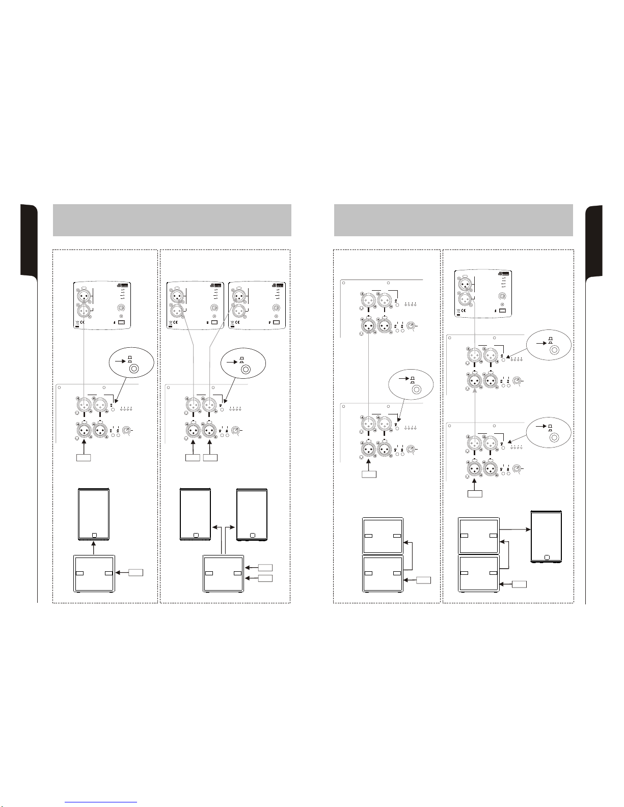
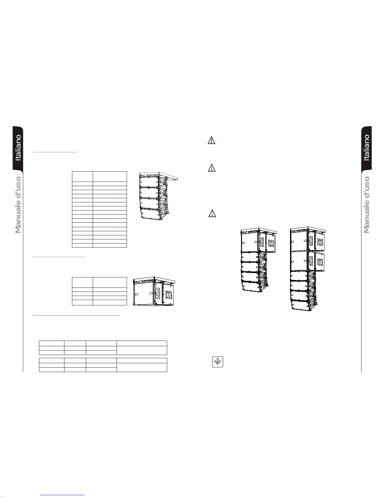
CONFIGURAZIONI e
CONFIGURATION and
KONFIGURATIONEN und
CONFIGURATIONS et
COLLEGAMENTI
CABLE CONNECTIONS
VERKABELUNG
CABLAGE
CONFIGURAZIONI e
CONFIGURATION and
KONFIGURATIONEN und
CONFIGURATIONS et
COLLEGAMENTI
CABLE CONNECTIONS
VERKABELUNG
CABLAGE
LINK
XOVER
ON MUTE SGN LIM
PHASE
90Hz
8
0dB
Mono
OUT 1 OUT 2
120Hz 0°
180°
XOVER
SUB-WOOFER
LEVEL
LINK
XOVER
0dB
Stereo
INPUT 1
MONO
BALANCED
INPUTS
BALANCED
OUTPUTS
INPUT 2
1122
33
1 = GND
2 = HOT
3 = COLD
12 3
PUSHPUSH PUSHPUSH
ON MUTE SGN LIM
PHASE
90Hz
8
0dB
Mono
OUT 1 OUT 2
120Hz 0°
180°
XOVER
SUB-WOOFER
LEVEL
LINK
XOVER
0dB
Stereo
INPUT 1
MONO
BALANCED
INPUTS
BALANCED
OUTPUTS
INPUT 2
1122
33
1 = GND
2 = HOT
3 = COLD
12 3
PUSHPUSH PUSHPUSH
MIXER
SS
00
SS
00
LINK
XOVER
MIXER
CONFIGURAZIONI e
CONFIGURATION and
KONFIGURATIONEN und
CONFIGURATIONS et
COLLEGAMENTI
CABLE CONNECTIONS
VERKABELUNG
CABLAGE
MONO
MIXER MIXER
ACTIVE SUBWOOFER
STEREO
MONO
MIXER
MIXER
ACTIVE SPEAKER
MIXER
ACTIVE SPEAKER
MONO
LINK
XOVER
LINK
XOVER
ACTIVE SUBWOOFER
ACTIVE SUBWOOFER
18
17
CONFIGURAZIONI e
CONFIGURATION and
KONFIGURATIONEN und
CONFIGURATIONS et
COLLEGAMENTI
CABLE CONNECTIONS
VERKABELUNG
CABLAGE
READY
MUTE
SIGNAL
LIMITER
SENSITIVITY
0dB
8
+4dB
MODE
-3dB
BALANCED
INPUT
LINK
OUT
PUSH
FLAT
STAGEMONITOR
ON MUTE SGN LIM
PHASE
90Hz
8
0dB
Mono
OUT 1 OUT 2
120Hz 0°
180°
XOVER
SUB-WOOFER
LEVEL
LINK
XOVER
0dB
Stereo
INPUT 1
MONO
BALANCED
INPUTS
BALANCED
OUTPUTS
INPUT 2
1122
33
1 = GND
2 = HOT
3 = COLD
12 3
PUSHPUSH PUSHPUSH
ACTIVE SPEAKER
MIXER
LINK
XOVER
ACTIVE SUBWOOFER
MIXER
LINK
XOVER
READY
MUTE
SIGNAL
LIMITER
SENSITIVITY
0dB
8
+4dB
MODE
-3dB
BALANCED
INPUT
LINK
OUT
PUSH
FLAT
STAGEMONITOR
ON MUTE SGN LIM
PHASE
90Hz
8
0dB
Mono
OUT 1 OUT 2
120Hz 0°
180°
XOVER
SUB-WOOFER
LEVEL
LINK
XOVER
0dB
Stereo
INPUT 1
MONO
BALANCED
INPUTS
BALANCED
OUTPUTS
INPUT 2
1122
33
1 = GND
2 = HOT
3 = COLD
12 3
PUSHPUSH PUSHPUSH
LINK
XOVER
LINK
XOVER
MIXER
READY
MUTE
SIGNAL
LIMITER
SENSITIVITY
0dB
8
+4dB
MODE
-3dB
BALANCED
INPUT
LINK
OUT
PUSH
FLAT
STAGEMONITOR
ON MUTE SGN LIM
PHASE
90Hz
8
0dB
Mono
OUT 1 OUT 2
120Hz 0°
180°
XOVER
SUB-WOOFER
LEVEL
LINK
XOVER
0dB
Stereo
INPUT 1
MONO
BALANCED
INPUTS
BALANCED
OUTPUTS
INPUT 2
1122
33
1 = GND
2 = HOT
3 = COLD
12 3
PUSHPUSH PUSHPUSH
ON MUTE SGN LIM
PHASE
90Hz
8
0dB
Mono
OUT 1 OUT 2
120Hz 0°
180°
XOVER
SUB-WOOFER
LEVEL
LINK
XOVER
0dB
Stereo
INPUT 1
MONO
BALANCED
INPUTS
BALANCED
OUTPUTS
INPUT 2
1122
33
1 = GND
2 = HOT
3 = COLD
12 3
PUSHPUSH PUSHPUSH
ACTIVE SUBWOOFER
ACTIVE SUBWOOFER
ON MUTE SGN LIM
PHASE
90Hz
8
0dB
Mono
OUT 1 OUT 2
120Hz 0°
180°
XOVER
SUB-WOOFER
LEVEL
LINK
XOVER
0dB
Stereo
INPUT 1
MONO
BALANCED
INPUTS
BALANCED
OUTPUTS
INPUT 2
1122
33
1 = GND
2 = HOT
3 = COLD
12 3
PUSHPUSH PUSHPUSH
MIXER
ON MUTE SGN LIM
PHASE
90Hz
8
0dB
Mono
OUT 1 OUT 2
120Hz 0°
180°
XOVER
SUB-WOOFER
LEVEL
LINK
XOVER
0dB
Stereo
INPUT 1
MONO
BALANCED
INPUTS
BALANCED
OUTPUTS
INPUT 2
1122
33
1 = GND
2 = HOT
3 = COLD
12 3
PUSHPUSH PUSHPUSH
READY
MUTE
SIGNAL
LIMITER
SENSITIVITY
0dB
8
+4dB
MODE
-3dB
BALANCED
INPUT
LINK
OUT
PUSH
FLAT
STAGEMONITOR
ACTIVE SPEAKER
LINK
XOVER
MIXER

19 20
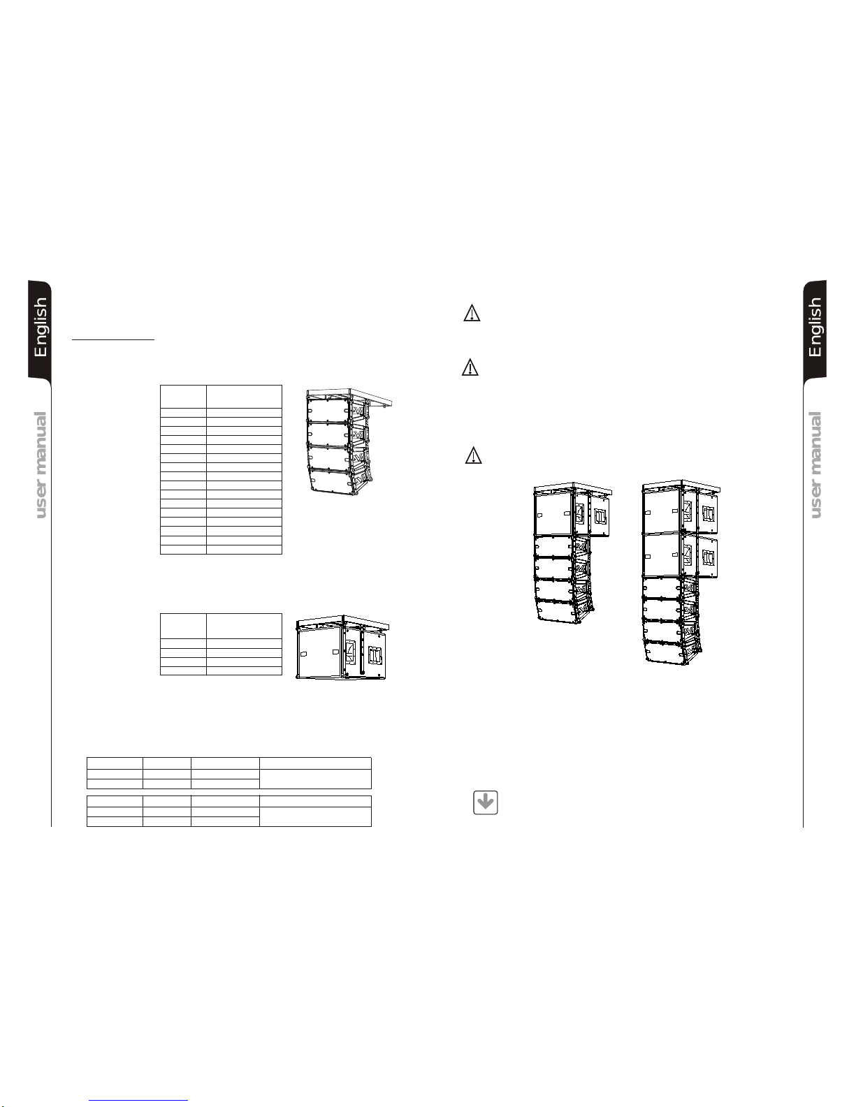
ATTENZIONE
Installareildiffusoreinmodostabileesicuro,cosìdaevitarequalsiasicondizione
dipericoloperl’incolumitàdipersoneestrutture.
Per evitare condizioni di pericolo non sovrapporre fra loro più diffusori senza
adeguatisistemidiancoraggio.
Nell’utilizzoall’apertoevitareluoghiespostialleintemperie.
Il diffusore viene fornito dalla ditta costruttrice predisposto per l’utilizzo in
appoggio.
ATTENZIONE
Non utilizzare mai le maniglie per appendere il diffusore!
INSTALLAZIONE DEL DIFFUSORE
LOUDSPEAKER INSTALLATION
INSTALLATION DES LAUTSPRECHERS
INSTALLATION DU DIFFUSEUR
WARNING
Never use the handles to hang the speaker!
WARNING
Make sure that the loudspeaker is securely installed in a stable position to avoid
anyinjuriesordamagestopersonsorproperty.
Forsafetyreasonsdonotplaceoneloudspeakerontopofanotherwithoutproper
fasteningsystems.
If you use the loudspeakers outdoors avoid places that are exposed to bad
weather.
VORSICHT
Hängen Sie den Lautsprecher nie an den Griffen auf!
ACHTUNG
DenLautsprecher aufeinestabileund sichereArtund Weiseinstallieren,um jede
GefahrfürPersonenoderSachschädenzuvermeiden.
Um gefährliche Situationen zu vermeiden, nie mehrere Lautsprecher ohne
angemessene Abspannsysteme aneinander anschließen. Zum Fliegen
verwendensienurdasSRK09originaldBTechnologiesFlyKit!
Bei Verwendung im Freien sollte man darauf achten, das die Lautsprecher vor
witterungseinflüssenwieSturm,Regen,Hagel,Schnee,usw.geschütztsind.
Aus Sicherheitsgründen, sollten sie beim über einander stellen von Subwoofern
daraufachten, dassdiesenicht verrutschen oderumfallenkönnen. DasGehäuse
ist mit einem M20 Hochständerflansch ausgestattet zur Aufnahme von
Distanzstangen
ATTENTION
Installerle diffuseur de façon stableetsûreafind'évitertouteconditiondedanger
pourl'intégritédespersonnesetdesstructures.
Afin d'éviter les conditions de danger, ne pas superposer entre eux plusieurs
diffuseurssanssystèmesd'ancrageappropriés.
Lorsdel'utilisationenespaceaérés,éviterleslieuxexposésauxintempéries.
Le diffuseur est fourni par l'entreprise qui le fabrique et il est prédisposé pour
l'utilisationenappui
ATTENTION
Ne jamais utiliser les poignées pour suspendre l'enceinte!
I
E
D
F
F
D
I
E
Escluso DVA S09dp Bianco
DVA S09dp White excluded
DVA S09dp White ausgeschlossen
DVAS09dp Blanc exclus
ContattaredBTechnologiesper gliaccessoridautilizzareacorredo.
Si declina ogni responsabilità da un utilizzo inappropriato degli accessori o di dispositivi aggiuntivi non idonei allo
scopo.
ContactdBTechnologiesforaccessoriestobe usedwithspeakers.
Willnotacceptanyresponsibilty wheninappropriateaccessoriesornotsuitableadditional devicesareused.
KontaktierensiedBTechnologies fürpassendesLautsprecherzubehör.
FallsunpassendesZubehörverwendetwird, wirdjeglicheHaftungausgeschlossen.
ContactdBTechnologies pourlesaccessoiresà utiliseraveclamachine.
N'accepterons pas toutes les responsabilités lorsque des accessoires inappropriés ou ne conviennent pas à des
dispositifssupplémentairessontutilisés.
ISTRUZIONI DI SICUREZZA PER ACCESSORI /
ZUBEHÖR NSTRUCTIONS DE SÉCURITÉ
SAFETY INSTRUCTIONS FOR ACCESSORIES
SICHERHEITSHINWEISE / I POUR LES ACCESSOIRES
21 22
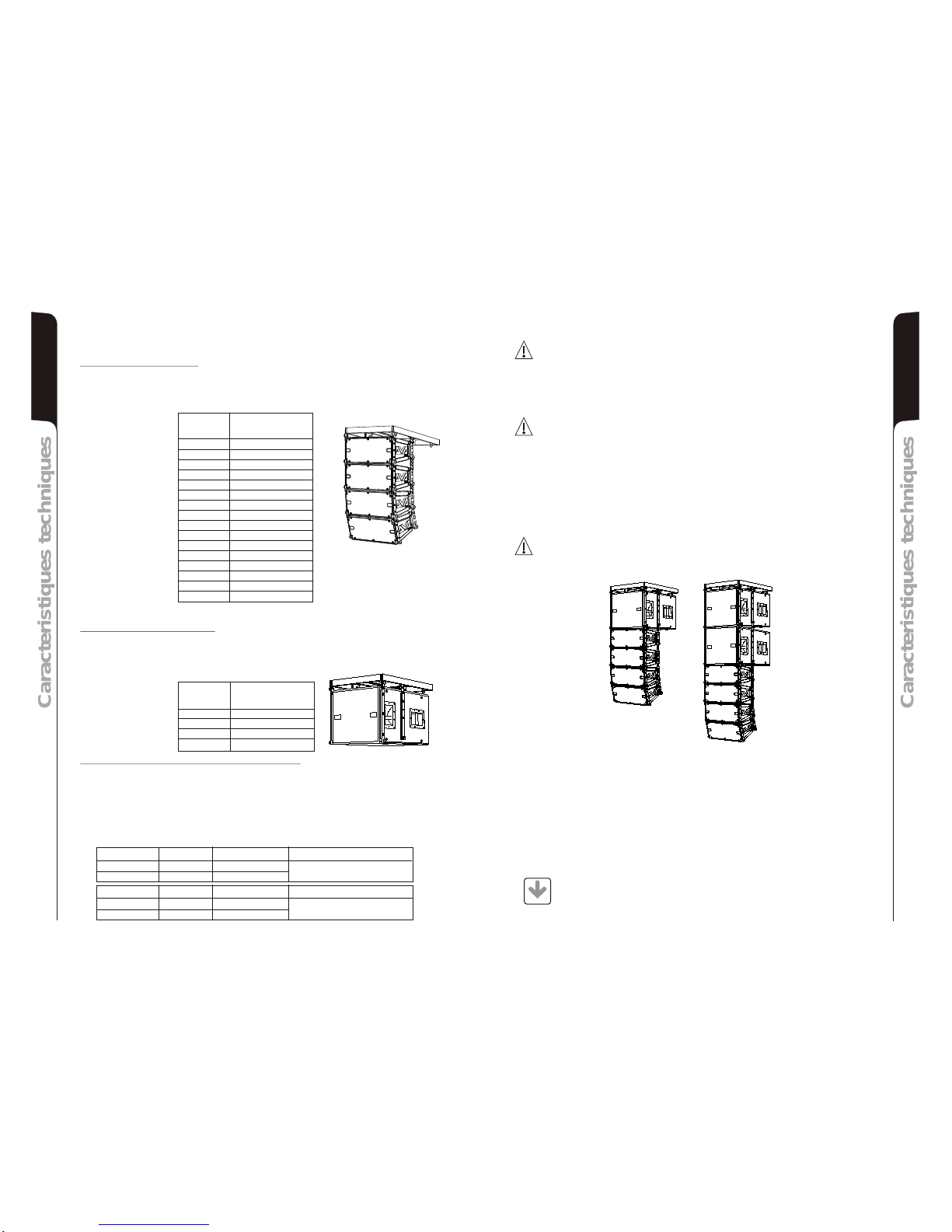
INSTALLAZIONE
La sospensione dei diffusori DVA T4 e DVA S09dp viene effettuata tramite la staffa
flybarDRK10.
IlpesomassimoapplicabilealflybarDRK10 èdi250kg.
Configurazioni con DVAT4
IlflybarDRK10ècertificatoperunmassimodi16diffusoriT4
Fare riferimento alla tabella 1 per determinare il peso complessivo sopportato dal flybar
condiffusoriDVAT4indiverse configurazioni
Tabella1 Quantità Peso
[kg] [lbs.]
1 15 33
2 30 66
3 45 99
4 60 132
5 75 165
6 90 198
7 105 231
8 120 264
9 135 297
10 150 330
11 165 363
12 180 396
13 195 429
14 210 462
15 225 495
16 240 528
Configurazioni con DVAS09dp
IlflybarDRK10ècertificatoperunmassimodi4diffusoriDVAS09dp
Fare riferimento alla tabella 2 per determinare il peso complessivo sopportato dal flybar
condiffusoriDVAS09dpindiverse configurazioni
Tabella2
Quantità Peso
[kg] [lbs.]
1 51 113
2 102 225
3 153 337
4 204 449
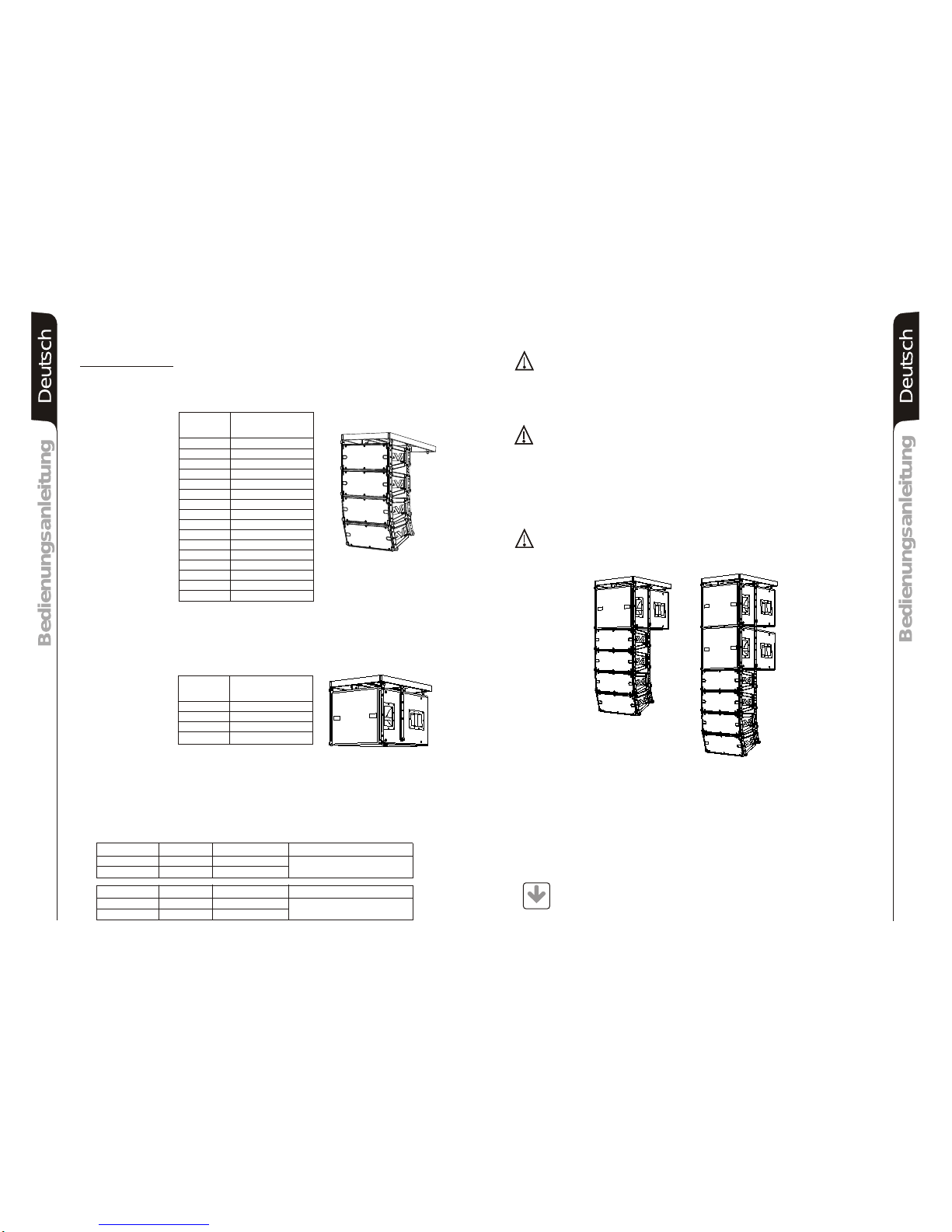
Configurazioni con miste con DVA T4 e DVA S09dp
La modularità del sistema DVA permette configurazioni sospese miste tra diffusori
DVAT4 e DVA S09dp. E’necessario considerare che un subwoofer DVAS09dp appeso
corrisponde,interminidipeso,a4diffusoriDVAT4.
Perquestomotivoènecessariocalcolareilcaricototalenellediversecombinazioni.
Esempio:
Modifiche strutturali alla supporto flybar DRK10
Accessori originali dBTechnologies
Nonpossonoessereeseguitemodifichesenzailconsensodelproduttore.
Attenzione
Nel caso in cui le suddette norme di sicurezza e il calcolo dei peso totale non siano
rispettate la dB Technologies non è responsabile di eventuali danni a cose e
persone!
UtilizzaresolopartiaccessorieoriginalidBTechnologies.
Attenzione
Non è stato omologato nessun altro accessorio per questo uso, pertanto
dBTechnologiesdeclinaogniresponsabilitàdieventualidanniacoseepersone!
Installaresemprelepartiinconformitàconquesteistruzionidiinstallazione!
CompilareearchiviaretuttiidocumentidelsistemaDVA inunpostosicuro!
Note
Duranteleinstallazioniaccertarsiche nella struttura portantedelsistemavenganoinclusi
nelcalcolodeipesi totali ancheilpesodel flybar DRK 10, delle catene dei sollevatori,dei
motori,deicavieulterioripesiaggiuntivi.
Attenzione
Le normative sulla sicurezza possono essere diverse in funzione del paese di
destinazione. Verificare le normative valide in accordo con il regolamenti sulle
sicurezzedelpaese!
Quantità Peso x qtà Peso configurazione
DVA T4 8 120Kg
DVA S09dp 2 102Kg 222Kg
Quantità Peso x qtà Peso configurazione
DVA T4 12 180Kg
DVA S09dp 1 51Kg 231Kg
ItalianoItalianoItaliano
ItalianoItalianoItaliano
Manuale d’usoManuale d’uso
Manuale d’usoManuale d’uso
DVA Composer - Simulazione acustica di sistemi serie DVA
DVA Composer è un software di puntamento e simulazione acustica per tutti i modelli
Line Array della serie DVA e relativi Subwoofer.
Tale software permette di gestire un sistema stereo composto da line array e subs,
simulando separatamente la risposta acustica di entrambi.
Vengono inoltre fornite all'utente una serie di informazioni quali allineamento in fase
tra i sistemi sospesi e i relativi subwoofer a terra e vengono suggeriti angoli ottimali tra
i moduli line array e relativi preset di equalizzazione, al fine di ottimizzare le
performance del sistema anche per utenti non esperti.
Si raccomanda di scaricare il software gratuito DVA_Composer
direttamente dal sito dB Technologies (www.dbtechnologies.com) nella
sezione dedicata «Software & Controller»
DOWNLOAD
23 24
INSTALLATION
The suspension of DVA T4 and speakers is made through flybar stirrup
DRK 10.
The maximum weight applying to DRK 10 flybar is 250Kg.
TheDRK10flybaratteststhatthemaximumnumberofDVAT4is16.
Refer to table 1 to determine the total weight borne by flybar according to the different
DVAT4configurations.
Table1 Quantity Weight
[kg] [lbs.]
1 15 33
2 30 66
3 45 99
4 60 132
5 75 165
6 90 198
7 105 231
8 120 264
9 135 297
10 150 330
11 165 363
12 180 396
13 195 429
14 210 462
15 225 495
16 240 528
TheDRK10flybaratteststhatthemaximumnumberof is 4.
Refer to table 2 to determine the total weight borne by flybar according to the different
onfigurations.
Table2
Quantity Weight
[kg] [lbs.]
DVA S09dp
DVAS09dp
DVAS09dpc
1 51 113
2 102 225
3 153 337
4 204 449
The modular structure of DVA system permits mixed suspension configuration between
DVA T4 and DVA S09dp. It is necessary to consider that one DVA S09dp hanging
subwoofercorresponds,inweightterms,tofourDVAT4speakers.
For this reason it is necessary to calculate the total weight according to the different
configurations.
DVA T4 configuration
configuration
Mixed configuration with DVA T4 and
DVA S09dp
DVA S09dp
Structural modification of DRK 10 flybar
Note
Nostructuralmodificationsmaybemadewithoutthemanufacturer'sconsent.
Warning
Ifthesecurity normsand totalweightcalculationsarenotobserved,dBTechnologies
isnotresponsibleforanypossibledamagetopeopleandthings.
UseonlydBTechnologiesoriginalparts.
Warning
For this use no other parts are homologated, dB Technologies to refuse all
responsabilityforanypossibledamagetopeopleandthings.
Alwaysinstallpartsinaccordancewiththeseinstallationinstruction!
CompileandstoreallDVAsystemdocumentsinasafeplace!
During installation ensure that carrying structure of the system has added in the total
weightalsotheDRK10flybarweight,chainhoists,motors,cablesandfurtherweights.
Warning
The safety regulations might be different in other countries. Please check with your
nationalsafetyauthoritythevalidregulations!
Original parts dB Technologies
Quantity Weight x qty Configuration weight
DVA T4 8 120Kg
DVA S09dp 2 102Kg 222Kg
Quantity x qty Configuration weight
DVA S09dp 51Kg
Weight
DVA T4 12 180Kg
1 231Kg
EnglishEnglishEnglish
EnglishEnglishEnglish
user manualuser manual
user manualuser manual
DVAComposer AcousticalSimulationandaimingforDVASystems
DVA Composer is a 2D software for aiming and simulating acoustical response of all line
arraysandSubwoofersfromDVASeries.
The software allows you to set up a stereo system composed by tops and subs, and
simulatesseparatelytheacousticalresponseofboth.
DVA Composer also gives to the user all the information about phase alignment between
flown systems and ground stacked subwoofers, as well as it suggests an optimized
aiming of the line arrays modules and their suggested EQ presets, in order to guarantee
maximumperformancesevenfornon-expertcustomers.
It is recommended to download DVA_Composer free software directly from
dBTechnologies(www.dbtechnologies.com)inthespecialsection«Software
&Controller»
DOWNLOAD
26
INSTALLATION
DieAufhängungdesDVAT4undS09dperfolgtmittels demFlugrahmenDRK10.
DasmaximalzulässigeGewichtdesFlugrahmensDRK10250kg.
DVA T4 Konfiguration
Es dürfen maximal 16 T4 Topteile an einem DRK 10 Flugrahmen befestigt werden.
Entsprechend Tabelle 1 bestimmen sie das Gesamtgewicht und Belastung des DRK 10
FlugrahmensverschiedenerDVAT4Konfigurationen
Tabelle1 Anzahl Gewicht
[kg] [lbs.]
1 15 33
2 30 66
3 45 99
4 60 132
5 75 165
6 90 198
7 105 231
8 120 264
9 135 297
10 150 330
11 165 363
12 180 396
13 195 429
14 210 462
15 225 495
16 240 528
DVA S09dp Konfigurationen
Es dürfen maximal 4 S09dp Subwoofer an einem DRK 10 Flugrahmen befestigt werden.
Entsprechend Tabelle 2 bestimmen sie das Gesamtgewicht und Belastung des DRK 10
FlugrahmensverschiedenerDVAS09dpKonfigurationen
Tabelle2
Anzahl Gewicht
[kg] [lbs.]
1 51 113
2 102 225
3 153 337
4 204 449
Gemischte Konfigurationen mit DVA T4 und DVA S09dp
Die mechanische Konstruktion des DVA Systems erlaubt eine gemischte Konfiguration
zwischen DVA T4 und DVA S09dp. Es ist wichtig zu beachten, dass ein geflogener DVA
S09dp Subwoofer dem Gewicht von vier DVA T4 entspricht. Aus diesem Grund ist es
notwendig, das Gesamtgewicht entsprechend der unterschiedlichen Konfigurationen zu
bestimmen.
Beispiele:
Veränderungen an dem DRK 10 Flugrahmen
Hinweis
Es dürfen ohne zustimmung des Herstellers keine bauartlichen Veränderungen
vorgenommenwerden.
Warnung
Werden die Sicherheitsvorschriften und die maximal zulässigen Gewichte nicht
beachtet, ist dB Technologies nicht verantwortlich für irgendwelche Schäden an
PersonenoderSachen.
NuroriginaleZubeh rteilevon dBTechnologieswerwenden.
Warnung
Für diesen Zweck ist kein anderes Zubeh rzugelassen, deswegen wendet dB
Technologiesjeglice Verantwortung an Personen-oder Sachscäden ab.
DieTeileimmer gemäß derBedienungsanleitunginstallieren!
AlleDokumentedesDVA-Systemssorgfältigaufbewahren!
Stellen Sie zur Installation sicher, dass die Tragevorrichtung für das Systems auch die
Gewichte des DRK 10 Flugrahmens, des Motors, des Kettenzuges, der Kabel und
andererGewichtetragenkann.
Warnung
Sicherheits-Vorschriften kann sich je nach dem Bestimmungsland. Überprüfen
Sie die geltenden Vorschriften in Einklang mit den Vorschriften über die
Sicherheit in dem Land!
OriginaldBTechnologiesTeile
ö
ö
Anzahl Gewicht x Anzahl Konfigurationen Gewicht
DVA T4 8 120Kg
DVA S09dp 2 102Kg 222Kg
Anzahl Gewicht x Anzahl Konfigurationen Gewicht
DVA T4 12 180Kg
DVA S09dp 1 51Kg 231Kg
DeutschDeutschDeutsch
DeutschDeutschDeutsch
25
BedienungsanleitungBedienungsanleitung
BedienungsanleitungBedienungsanleitung
DVA Composer Akustiksimulation für Systeme der Serie DVA
DVA Composer ist eine Software zur Beschallungsplanung und simulation für alle Line
Array-ModellederSerieDVAunddenzugehörigenSubwoofern.
SieermöglichtdieVerwaltungeinesStereosystems,dasausLineArraysundSubwoofern
besteht,wobeidasakustischeAnsprechprofiljeweilsseparatsimuliertwird.
DemNutzer werdeneineReihe vonDatengeliefert,z.B. diePhasenanpassungzwischen
den Hängesystemen und den entsprechenden Subwoofern am Boden. Außerdem
werdendieoptimalenWinkel zwischendenLineArray-Modulenunddenentsprechenden
Equalizer-Presetsangegeben,so dass auch weniger erfahrene Benutzer die Leistungen
desSystemsoptimierenkönnen.
Wir empfehlen, die Software DVA_Composer direkt von der Webseite dB
Technologies (www.dbtechnologies.com) im Abschnitt «Software &
Controller»herunterzuladen
DOWNLOAD
27 28
INSTALLATION
LasuspensiondesDVAT4etDVAS09dp sefaità traverslesupport flybarDRK10.
Lepoidsmaximalapplicableàlaflybar DRK10est250 kg.
Configurations avec DVAT4
LeflybarDRK10estcertifiépourunmaximumde16diffuseursT4
Consulter le tableau 1 afin de déterminer le poids compressif supporté par le flybar avec
diffuseursDVAT4dansdifférentesconfigurations.
Tableau1 Quantité Poids
[kg] [lbs.]
1 15 33
2 30 66
3 45 99
4 60 132
5 75 165
6 90 198
7 105 231
8 120 264
9 135 297
10 150 330
11 165 363
12 180 396
13 195 429
14 210 462
15 225 495
16 240 528
Configurations avec DVAS09dp
LeflybarDRK10estcertifiépourunmaximumde4diffuseurs4DVAS09dp.
Consulter le tableau 2 afin de déterminer le poids compressif supporté par le flybar avec
diffuseursDVAS09dpdansdifférentesconfigurations.
Tableau2
Quantité Poids
[kg] [lbs.]
1 51 113
2 102 225
3 153 337
4 204 449
Configurations avec mélange DVA T4 et DVA S09dp
La modularité du système DVA permetdesconfigurationssuspenduesmixtesentreles
diffuseurs DVA T4 et DVA S09dp. Il est nécessaire de considérer qu'un subwoofer DVA
S09dpsuspenducorrespond,entermedepoids,à4diffuseursDVAT4.
C'est pour ce motif qu'il est nécessaire de calculer la charge totale dans les différentes
combinaisons.
Exemple:
Modifications de structure sur le support flybar DRK10
Notes
Aucunemodificationnepeutêtrefaitesansl'accordduproducteur.
Attention
Dans le cas où lesdites mesures de sécurité et de calcul de poids total ne sont pas
respectées, dB Technologies n'est en aucun cas responsable des éventuels
dommagesprovoquésauxobjetsetauxpersonnes!
N'utiliser exclusivement que des pièces originales dBTechnologies.
Attention
Il n'y a pas d'autre accessoire approuvé pour cet usage, afin dB Technologies
n'assume aucune responsabilité pour les dommages causés à des biens et des
personnes!
Installertoujourslespartiesenconformitéaveccesinstructionsd'installation!
RempliretmettreauxarchivestouslesdocumentsdusystèmeDVA dansunlieusûr!
Durant les installations, bien s'assurer que dans la structure portante du système soient
inclusdanslecalculdespoidstotauxainsiquelepoidsduflybarDRK10,deschaînesdes
élévateurs,desmoteurs,descâblesetautrespoidsajoutés.
Attention
Les normes sur la sécurité peuvent être différentes en fonction du pays de
destination. Vérifier les normes en rigueur en accord avec les règlements sur les
sécuritésdupays!
Accessoires originaux dBTechnologies
Quantité Poids par quantité Poids configuration
DVA T4 8 120Kg
DVA S09dp 2 102Kg 222Kg
Quantité Poids par quantité Poids configuration
DVA T4 12 180Kg
DVA S09dp 1 51Kg 231Kg
Français
Caracteristiques techniquesCaracteristiques techniques
Caracteristiques techniquesCaracteristiques techniques Français
DVAComposer SimulationacoustiquedesystèmesdesériesDVA
DVA Composer est un logiciel de direction et simulation acoustique pour tous les
modèles de lignes de source de la série DVA et les caissons de basse relatifs.
Ce logiciel permet de gérer un système stéréo composé de ligne source et de
caissons de basse, simulant séparément la réponse acoustique de chacun des deux.
De plus, de nombreuses informations sont fournies à l'utilisateur, comme l'alignement
en phase entre les systèmes suspendus et les relatifs caissons de basse à terre, ou la
syggestion d'angles optimisés entre les modules de ligne de source et les préréglages
d'égaliseur relatifs. Cela permet d'optimiser les performances du système, même pour
des utilisateurs non experts.
On conseille de télécharger gratuitement le logiciel DVA_Composer
directement à partir du site dB Technologies (www.dbtechnologies.com)
dans la section dédiée « Software & Controller »
DOWNLOAD

29 30
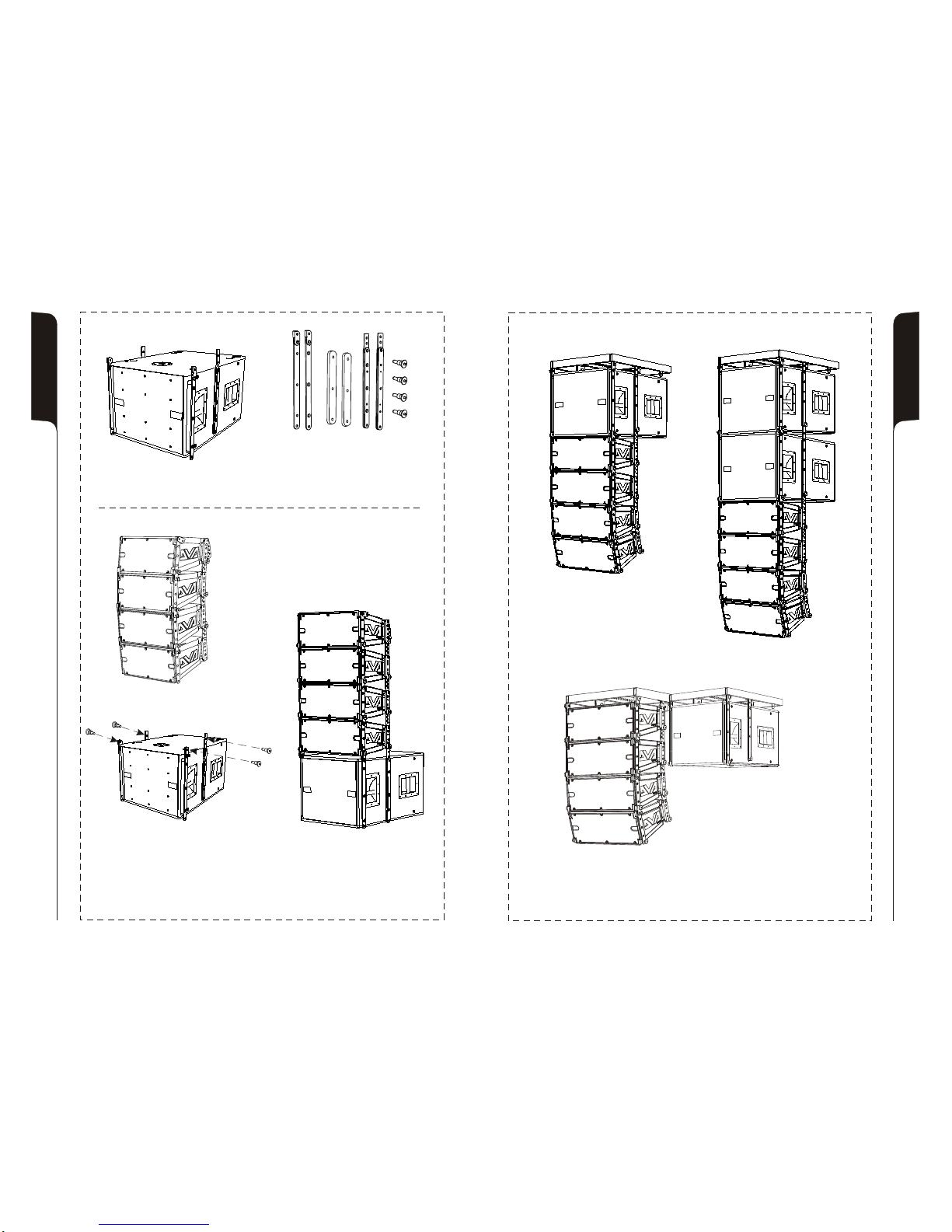
INSTALLAZIONE
INSTALLATION
INSTALLATIONEN
INSTALLATIONS
In appoggio - impilato
Groundstack - stacked
In appoggio
Groundstack
In appoggio con flybar (opzione DRK 10)
Groundstack with flybar (DRK 10 option)
Escluso DVA S09dp Bianco
DVA S09dp White excluded
DVA S09dp White ausgeschlossen
DVAS09dp Blanc exclus
32
31
Appeso con kit staffe (opzione SRK-09) e flybar (opzione DRK-10)
Hang with stirrups kit (SRK-09 option) and flybar (DRK-10 option)
Kit staffe- opzione SRK-09
Kit stirrups - SRK-09 option
In appoggio con kit staffe
Groundstack with kit stirrups

33 34
In appoggio son supporto su asta
per Groundstack with stand adaptor
Set di 4 ruote - opzione DWK 20
Set of 4 wheels - DWK 20 option
In appoggio a pavimento con supporto asta provvisto di piedi
Groundstack to floor with stand adaptor with feet
Per supporto asta
Stand adaptor
Opzione DSA 4
DSA 4 Option
In appoggio
Floor stack
Escluso DVA S09dp Bianco
DVA S09dp White excluded
DVA S09dp White ausgeschlossen
DVAS09dp Blanc exclus
Escluso DVA S09dp Bianco
DVA S09dp White excluded
DVA S09dp White ausgeschlossen
DVAS09dp Blanc exclus
Table of contents
Other AEB Subwoofer manuals


