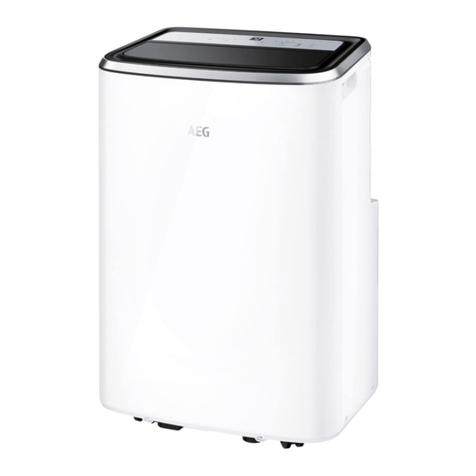
AEG EXN09C58HW User manual

EN AIR CONDITIONER
NO KLIMAANLEGG
DA KLIMAANLÆG
SE LUFTKONDITIONERING
FI ILMASTOINTILAITE
INSTALLATION MANUAL
INSTALLASJONSHÅNDBOK
INSTALLATIONSMANUAL
INSTALLATIONSMANUAL
ASENNUSOHJEET
2
24
46
68
90
EXN09C58HW
EXN12C58HW
EPN09C58HW
EPN12C58HW
EPN09C38HW
EPN12C38HW
EPN18C38HW

2 www.electrolux.com
WE’RE THINKING OF YOU
Thank you for purchasing an Electrolux appliance. You’ve chosen a product that brings
with it decades of professional experience and innovation. Ingenious and stylish, it
has been designed with you in mind. So whenever you use it, you can be safe in the
knowledge that you’ll get great results every time.
Welcome to Electrolux.
Visit our website to:
Get usage advice, brochures, trouble shooter, service information:
www.electrolux.com
Register your product for better service:
www.electrolux.com/productregistration
Buy Accessories, Consumables and Original spare parts for your appliance:
www.electrolux.com/shop
CUSTOMER CARE AND SERVICE
We recommend the use of original spare parts.
When contacting Service, ensure that you have the following data available.
The information can be found on the rating plate. Model, PNC, Serial Number
Warning / Caution-Safety information.
General information and tips.
Environmental information.
Subject to change without notice.
CONTENTS
1. SAFETY INSTRUCTIONS ..................................................................................3
2. BEFORE INSTALLATION ...................................................................................5
3. PRODUCT INSTALLATION ................................................................................8
4. TEST AND RUNNING.......................................................................................19
5. APPENDIX ........................................................................................................21
6. F-GAS INFORMATION .....................................................................................22

3ENGLISH
1. SAFETY INSTRUCTIONS
Before the installation and use of the
appliance, carefully read the supplied
instructions. The manufacturer is not
responsible if an incorrect installation
and use causes injuries and damages.
Always keep the instructions with the
appliance for future reference.
1.1 Children and vulnerable
people safety
WARNING!
Risk of suocation, injury or
permanent disability.
• This appliance can be used by
children aged from 8 years and above
and persons with reduced physical,
sensory or mental capabilities or
lack of experience and knowledge
if they have been given supervision
or instruction concerning use of
the appliance in a safe way and
understand the hazards involved.
• Children shall not play with the
appliance.
• Cleaning and user maintenance
shall not be made by children without
supervision.
1.2 Installation and Use
WARNING!
Risk of suocation, injury or
permanent disability.
• Contact an authorised installer for
installation of this unit.
• Contact an authorised service technician
for repair or maintenance of this unit.
• The socket outlet required to
supply power must be connected
and commissioned by a licenced
contractor.
• If the supply cord is damaged, it must
be replaced by the manufacturer, its
service agent or similarly qualied
persons in order to avoid a hazard.
• Installation work must be performed
in accordance with the national wiring
standards and the electricity suppliers
service rules by authorised personnel
only.
• If the unit is to be moved to another
location or disposed of, only a suitably
qualied person is permitted to
undertake such work.
• If you notice an unusal situation, such
as a burning smell, please switch o
the power to the air conditioner and
contact the brand service agent. If
this abnormal status continues the air
conditioner may be damaged or even
cause electric shock or re.
• Do not operate the air conditioner with
wet hands. This may cause electric
shock.
• Do not damage or cut o the power
cord or other wires. If this occurs,
please have it repaired or replaced by
an accredited technician.
• Do not connect this air conditioner to a
multi outlet power board.
• Please switch o the power supply to
the air conditioner if it is not to be used
for an extended period. Otherwise, it
will accumulate dust and may cause
a re.
• Before cleaning the air conditioner,
please disconnect the power supply
in order to eliminate the possibility of
electric shock.
• The power supply should be
matched with the air conditioner. Air
conditioners provided with a supply
cord should be connected directly to
a power outlet with a suitable safety
switch. Air conditioners that are hard
wired must be connected to a suitable
safety circuit breaker.
• Please ensure that the power supply
to the air conditioner is stable and
meets the requirements set out in the
installation manual.
• Always ensure the product is installed
with appropriate earthing.
• For safety, be sure to turn o the
circuit breaker before performing any
maintenance or cleaning or when the
product is not used for an extended
period of time. Accumulated dust may
cause re or electric shock.
• Select the most appropriate
temperature. It can save electricity.

4 www.electrolux.com
• Do not keep windows and doors open
for a long time during operation. It will
result in insufcient performance.
• Do not block the air inlet or outlet. It
will result in insufcient performance
and cause malfunctions.
• Keep combustible materials away from
the units at least 1meter. It may cause
re.
• Do not step on the top of the outdoor
unit or place heavy things on it. It may
cause damage or injury.
• Do not attempt to repair the air
conditioner by yourself. Incorrect repairs
may cause electric shock or re. Please
contact your local authorised service
centre.
• Do not insert your hands or objects into
the air inlet or outlet. It may cause injury.
• Do not expose animals or plants
directly to the airflow.
• Do not use the unit for any other
purpose, such as preserving food or
drying clothes.
• Do not splash water on the air
conditioner. It may cause electric
shock or malfunction.
R32 refrigerant warning
This product uses R32 difluoromethane
refrigerant, which is a mildly flammable
gas class 2.2 according to ISO 5149
and must be handled by a refrigeration
mechanic with appropriate refrigerant
handling licence.
1.3 Minimum Floor Areas
This product uses mildly flammable R32
refrigerant. Certain levels of refrigerant
require minimum room sizes. Please
ensure that these minimum room sizes
are adhered to for standard installations.
7\SH
5
/)/
NJP
7RWDO0DVV&KDUJHGNJ
0LPLPXPURRPDUHDP
KY
P

5ENGLISH
2. BEFORE INSTALLATION
2.1 Tools needs for installation
1. Level gauge
2. Screw driver
3. Electric drill
4. Hole core drill
5. Flaring tool set
6. Specied torque wrenches
7. Spanner (half union)
8. A glass of water
9. Hexagonal wrench
10. Gas-leak detector
11. Vacuum pump
12. Gauge manifold
13. Pipe expander
14. Multimeter
15. Pipe cutter
16. Measuring tape
17. Other tools
2.2 Accessories
Number Name of Accessories Quantity
1Indoor unit mounting plate 1
2Clip anchor Varies by models
3Self-tapping screws (for mounting plate) Varies by models
4Remote controller 1
5Remote controller Holder / Screws Optional
6Battery (AAA 1.5V) 2
7Piping hole cover Optional
8Pipe insulation belt 1
9Refrigerant piping (Liquid/Gas pipe) Optional
10 Signal cable
11 Drain hose 1
12 Cushion Optional
13 Drain connector (Heat Pump model only) Optional
14 Drain plug (Heat Pump model only) Optional
15 Flare nut (for gas pipe) Optional
16 Flare nut (for liquid pipe) Optional
17 Handle screw (for outdoor unit) Optional
18 Wall mud Optional
19 Magnetic ring Optional
20 Healthy lter** (Packed in the plastic bag) Varies by models
Note:
The accessory parts may vary from each model, please refer to the actual parts.
Other necessary parts for the installation, besides the above mentioned, must be
provided by the customer/installer.
** Please install the Healthy lter like Active carbon lter, Bio-Hepa lter, Vitamin C
lter, Silver ion lter or any other lters with the dust lter in the indoor unit. For some
models, we already have the Healthy lters installed in the indoor unit.
Optional

6 www.electrolux.com6 www.electrolux.com
2.3 Product Description
NOTE
All the pictures in this manual are for explanation purposes only. The actual
shape of the indoor unit you purchased may be slight different on front panel
and display window.The actual shape shall prevail.
≥15cm
≥15cm
Space to the wall
Space to obstruction
≥30cm
≥2m
Air outlet side
Air inlet side
≥50cm
Space to the wall
Space to the ceiling
≥15cm
Space to the wall
≥3m
Air outlet side
Space to the wall
≥50cm
1 23
4
20
5
6
13
14
15
16
11
7
10
9
8
17
18
19 12
≥30cm

7ENGLISH
2.4 Installation site
• Do not install the unit in areas with:
– strong heat sources;
– vapours or flammable gases;
– contamination with oil particles;
– high frequency electromagnetic
equipment (e.g. welding equipment
or medical devices);
– high salinity (e.g. close to coastal
areas);
– sulphuric gas (e.g hot water
springs);
– poor air quality.
Indoor unit
• Maintain the minimum installation
distances specied in this document.
Do not block the air inlet or the air
outlet.
• Do not use the unit in places with
extremely high humidity.
• Install the indoor unit out of reach of
children.
• The wall must be strong enough to
support the weight and vibration of
the unit.
• Install the indoor unit at least 230 cm
above the floor surface.
• Leave sucient space for cleaning and
maintenance.
• The air lter should remain accessible.
• Leave at least 1 m distance between
the unit and other electrical appliances.
• Install the indoor unit in a place where
the condensate water can be easily
drained.
• Install at a location protected from
direct sunlight.
Outdoor unit
• Maintain the minimum installation
distances specied in this document.
• Do not block the air inlet or the air outlet.
• Install the outdoor unit out of reach of
children.
• Install the outdoor unit where there is
sucient ventilation.
• Install the outdoor unit where produced
noise and airflow will not disturb
neighbors or animals.
• Install the outdoor unit in a dry place.
• Install the outdoor unit in a place not
exposed to direct sunlight or strong
wind.
• Install the outdoor unit in a place can
support the weight and vibration of
the unit.
• Leave sucient space for cleaning and
maintenance.
Safety precautions for electrical
appliances
• Use a dedicated mains circuit.
• The unit must be properly grounded.
• Install a Residual-current device (RCD)
to protect against personal injury in
case of leakage currents.
• The installation must comply with local
electrical safety regulations and with
other relevant local regulations.
• The unit must be installed in
accordance with national wiring
regulations.
• Do not subject the mains cable
to force.
• The distance between the unit and heat
sources is at least 1.5 m.
NOTE
• Make sure that the live wire, the
neutral wire and the ground wire in the
mains socket are properly connected.
• Inadequate or incorrect electrical
connections can cause electric shock
or re.

8 www.electrolux.com
3.1 Indoor unit installation
3.1.1 Installing the Wall
Mounting Plate
1. Install the wall mounting plate
horizontally over the structural parts
on the wall using the spaces indicated
on the plate, as shown in Fig.3.1.1.
2. In the case of tiled, concrete or
similar walls, create 5mm diameter
holes. Place anchor supports for the
appropriate assembly screws.
3. Install the wall mounting plate to the
wall with screws.
Fig.3.1.1
NOTE:
• Fit the wall mounting plate and drill
holes in the wall according to the wall
structure and corresponding mounting
points on the wall mounting plate.
• Refer to Appendix(1) for type details
about the mounting plates.
3.1.2 Drilling the Hole
1. Determine the position of the hole
for the pipes using the wall mounting
bracket and drill the pipe hole so that it
is tilted slightly downward.
2. Always use a pipe cover with an
opening when drilling.
Fig.3.1.2
PP
Wall
Indoor Outdoor
3. PRODUCT INSTALLATION
3.1.3 Connective pipe
1. For the left-hand and right-hand
piping, remove the pipe cover from the
side panel. The pipe cover can be kept
as it may be used when relocating the
air conditioner to any other place.
2. For the rear-right-hand and rear-
left-hand piping, install the piping
as shown in Fig.3.1.3-1. Bend the
connective pipe to be laid at a height
of 43mm or less from the wall. Fix the
end of the connective pipe.
Fig.3.1.3-1
Pipe Cover
(right)
Right
Piping
Rear Right
Piping Rear Left
Piping
Pipe Cover
(left)
Pipe Holder
Fig.3.1.3-2
Indoor Unit
Outline Connective Pipe
43mm
3.1.4 Drainage
1. Run the drain hose sloping downward.
Do not install the drain hose as
illustrated in Fig.3.1.4.
Fig.3.1.4
Do not block water flow by a rise or
put the end of drain hose into water.

9ENGLISH
2. When connecting extension drain
hose, insulate the connecting part of
extension drain hose with a shield
pipe, do not let the drain hose slack.
3.1.5 Fastening the Indoor Unit
1. Pass the piping through the hole in
the wall.
2. Put the upper claw at the back of
the indoor unit on the upper hook of
the wall mounting bracket, move the
indoor unit from side to side to see
that it is securely hooked.
Fig.3.1.5-1
3. Piping can easily be made by lifting
the indoor unit with a cushioning
material between the indoor unit and
the wall.
Fig.3.1.5-2
4. Push the lower part of the indoor unit
up on the wall, Then move the indoor
unit from side to side, up and down to
check if it is hooked securely.
Lower Hook
Upper Hook
Cushioning material
3.1.6 Piping and wrapping
1. Bundle the tubing, connecting cable,
and drain hose with tape securely and
evenly as shown in the Fig.3.1.6.
2. Because the condensed water from
rear of the indoor unit is gathered in
ponding box and is piped out of room,
do not put anything else in the box.
Fig.3.1.6
NOTE:
• Connect the indoor unit rst, then the
outdoor unit.
• Be careful not to let the drain hose
slack.
• Both of the auxiliary piping should be
heat insulated.
• Be sure that the drain hose is located
at the lowest side of the bundle.
Locating at the upper side may cause
drainage overflow inside the unit.
• Never intercross nor intertwist the
power wire with any other wire.
• Run the drain hose sloped downward
to drain out the condensed water
smoothly.
3.2 Outdoor unit installation
3.2.1 Securing of Outdoor Unit
1. Install the outdoor part of the unit on
a flat surface to avoid excess noise
and vibration. A condenser pad is
recommended.
2. Direct the air vent toward an area
without obstacles.
Cable
Connection
Ponding
Box
Pipe
Room
Connective
Pipe
Wrapping
Belt
Drain
Hose

10 www.electrolux.com
3. Install the unit at the site where it is
exposed to as little wind as possible,
especially not in areas where it is
frequently windy.
4. If the installation site is exposed to
heavy winds, such as in coastal areas,
place the unit along the widest part of
the wall or use protective plates.
5. Be sure there is no obstacle which
blocks exhausting air, including shrubs
or bushes.
Fig.3.2.1-1
NOTE:
• Settlement of outdoor unit. Anchor the
outdoor unit tightly and horizontally
on a concrete or flat mount with a bolt
and nut 10mm diameter (Purchased
separately).
Fig.3.2.1-2
Strong Wind
Air Inlet
Air Inlet
Air Outlet
3.2.2 Condensate drainage of
outdoor unit (only for heat
pump model)
1. During heating operation, the
condensate and defrosting water
should be drained out reliably through
the drain hose.
2. Install the outdoor drain connector in
the drain-water hole on the chassis of
outdoor unit, and attach the drain hose
to the connector so that the waste
water formed in the outdoor unit can
be drained out.
3. The drain-water hole must be plugged.
Whether to plug other holes will be
determined by the installer according
to actual conditions.
4. In case of a drain hose, the unit must
be installed on a base more than 3cm
height.
Fig.3.2.2
NOTE:
• For some heat pump models, no drain
connecter provided due to enough
drain-water hole designed.
3.3 Refrigerant piping
connection
NOTE:
• Keep original bend so no kinking of the
tube occurs.
Drain
connecter
Hose
(not provided)
Chassis
Drain-water
hole

11ENGLISH
3.3.1 Flaring work
Main cause for refrigerant leakage is due
to defect in the flaring work.
Carry out correct flaring work using the
following procedure:
1. Cut the pipes and the cable.
• Use the piping kit accessory or
pipes purchased locally.
• Measure the distance between the
indoor and the outdoor unit.
• Cut the pipes a little longer than the
measured distance.
• Cut the cable 1.5m longer than the
pipe length.
Fig.3.3.1-1
2. Burr removal
• Completely remove all burrs from
the cut cross section of pipe/tube.
• Put the end of the copper tube/
pipe in a downward direction as
you remove burrs in order to avoid
dropping burrs into the tubing.
Fig.3.3.1-2
Oblique BurrRoughness
Pipe
Reamer
Face Down
3. Put nut on
• Remove flare nuts attached to
indoor and outdoor unit, then put
them on pipe/tube after completed
burr removal. (It is not possible to
put them on after flaring work.)
Fig.3.3.1-3
4. Flaring work
• Carry out flaring work using flaring
tool as shown below.
Fig.3.3.1-4
• Firmly hold copper pipe according
to the dimension shown in the table
below.
2XWHUGLDPPP $PP
0D[ 0LQ
ರ
ರ
ರ
ರ
Flare Nut
Copper Tube
Bar
Copper
Pipe
Yoke
Handle
Bar
Cone
Red arrow
mark
Clamp Handle
"A"
Pipe

12 www.electrolux.com
3.4 Piping Connection
3.4.1 Indoor Unit
1. Connecting the indoor unit tubing to
the connection piping:
• Align the centers of the pipes and
suciently tighten the flare nut with
your hands rst.
Fig.3.4.1-1
Fig.3.4.1-2
• Then tighten the flare nut with
spanner and torque wrench by
referring the following table:
2XWHUGLDP
PP
7RUTXH
1P
$GGLWLRQDO
7RUTXH1P
ರ NJP NJP
ರ NJP NJP
ರ NJP NJP
ರ NJP NJP
2. Wrap the insulation material around
the connecting portion:
• Cover the indoor unit pipe and
the connection pipe with the heat
insulation material. Bind them
together with vinyl tape so that there
is no gap.
Spanner (xed)
Flare nut
Pipings
Wrench Torque
Indoor unit tubing
Fig.3.4.1-3
• Ensure to isolate separately the
suction pipe from the liquid pipe.
Fig.3.4.1-4
• Wrap the insulated pipes with vinyl
tape in the rear section for pipe
housing. Fasten the power cable
to the pipes with vinyl tape.
Fig.3.4.1-5
Fig.3.4.1-6
• Wrap the piping, drain hose and
power cable tightly with vinyl tape so
that they can t into the rear piping
housing section.
Fig.3.4.1-7
Cable Ties Insulation
Material
Heat Insulation
Suction line pipe Liquid line pipe
Connection pipe
Vinyl tape (wide) Wrap with vinyl tape
Indoor
Unit pipe
Pipe
Vinyl tape
(narrow)
Connection
cable
Pipe
Vinyl tape
(narrow)
Drain hose
Connection
power cable Wrap with
vinyl tape
(wide)
Indoor unit tubing
Torque wrench
Spanner
Flare nut Pipes

13ENGLISH
3. Hang the indoor unit:
• Remove the spacer.
• Hook the indoor unit onto the
upper portion of the mounting plate
(Engage the hooks of the mounting
plate into the openings at the rear
top of the indoor unit).
• Ensure that the hooks are properly
seated on the mounting plate
by moving the indoor unit in all
directions.
Fig.3.4.1-8
• Press the lower left and right sides
of the unit against the mounting
plate until the hooks engage into
their slots (clicking sound).
Fig.3.4.1-9
3.4.2 Outdoor Unit
1. Align the centers of the pipes and
sucientlytighten the flare nut with
your hands.
Upper hook
Mounting
plate
Spacer
Upper hook
Connecting
cable
Drain hose
Mounting plate
Fixing lower hook
Fig.3.4.2-1
2. Then, tighten the flare nut with torque
wrenchuntil the wrench clicks.
Fig.3.4.2-2
ZD\
YDOYH
• Make sure to follow the torque table
value as below table:
2XWHUGLDP
PP
7RUTXH
1P
$GGLWLRQDO
7RUTXH1P
ರ NJP NJP
ರ NJP NJP
ರ NJP NJP
ರ NJP NJP
3.4.3 Piping Formation
1. Form the piping by wrapping the
connecting portion of the indoor unit
with insulation material and secure it
with narrow vinyl tape and wide vinyl
tape.
• If you want to connect an additional
drain hose, the end of the drain
hose outlet should be routed above
the ground. Secure the drain hose
appropriately.
2. In cases where the outdoor unit is
installed below the indoor unit level:
• Wrap the piping, drain hose and
connecting cable from the down
to up.
Liquid
pipe
Outdoor Unit
Suction
pipe
3-way valve

14 www.electrolux.com
• Secure the wrapped piping along
the exterior wall using saddle or
equivalent.
Fig.3.4.3-1
3. In cases where the outdoor unit is
installed above the indoor unit level:
• Wrap the piping and connecting
cable from the down to up.
• Form a trap to prevent water from
entering the room.
• Secure the wrapped piping along
the exterior wall using saddle or
equivalent.
Fig.3.4.3-2
Seal small openings
around piping with
a gum type sealer
Trap is required to prevent water
from entering into electrical parts
Wrapping
Pipe
Drain
hose
Connection
cable
Drain hose
Seal small openings
around piping with
a gum type sealer
Trap
Trap
Drain hose
3.4.4 Checking the Drainage
1. Open and lift the indoor unit front
panel.
• Hold the lower part of the left and
right sides of the panel, pull it
against you and lift it stops with
support.
Fig.3.4.4-1
2. Check the drainage
• Carefully pour a glass of water on
the evaporator.
• Ensure the water flows through the
drain hose of the indoor unit without
any leakage and goes out the drain
exit.
Fig.3.4.4-2
3. Dain piping
• The drain hose should point
downward for easy drain flow.
Drain
hose

15ENGLISH
Fig.3.4.4-3
• Do not place drain piping as
indicated below:
Fig.3.4.4-4
3.5 Electrical Installation
3.5.1 Safety Precautions
Electrical safety rules before starting the
installation:
1. A dedicated power supply circuit and
breaker should be provided for the
products which are not supplied with
a service cord and plug in accordance
with local electrical safety regulations.
2. The circuit breaker must have the
functions of magnetic tripping and heat
tripping to prevent short circuit and
overload.
3. The appliance shall be installed
in accordance with national wiring
regulations.
4. A circuit breaker with proper capacity
must be installed.
5. In case of problems in power supply,
the air conditioner must not be
installed before the customer xes the
problem.
6. Be sure the power supply matches the
air conditioner.
Downward slope
Do not rise
Water leakage Water leakage
Water leakage
Accumulated
drain water
Tip of drain hose
dipped in water Space less
than 50mm
Air
Ditch
7. Ensure the live wire, neutral wire and
earth wire in the power socket are
properly connected.
8. Inadequate or incorrect electrical
connections may cause electric
shock, re or some electrical parts
to malfunction.
9. Before performing any electrical work,
turn o the main power to the system.
NOTE:
• Refer to Appendix(2) for correlative
specs about the Electrical Installation.
Earthing Requirements
1. The unit must be reliably earthed and
connected to the special earth device
by the qualied elctrician.
2. The yellow-green wire in air
conditioner is the earthing wire which
can not be used for other purposes.
Improper earthing may cause electric
shock.
3. The earth resistance should accord
to the national wiring regulation.
4. The user’s power must have reliable
earthing terminal. Do not connect the
earthing wire with the following:
• Water pipe
• Gas pipe
• Contamination pipe
3.5.2 Installation of Indoor
Electric Wires
1. Open the front panel and remove the
wiring cover by loosening the screw.
Fig.3.5.2-1
2. Route the power connection cable
and signal control wire (for heat pump
model only) from back of the indoor
unit and pull it toward the front through
the wiring hole for connection.
3. Pass the wires through the hole of the
Magnetic ring (If supplied).
Wiring cover

16 www.electrolux.com
4. Connect and screw the wires onto the
terminal block as identied by their
colors.
5. Wrap wires that are not connected
with insulating tape so that they do not
touch any electrical or metal parts.
6. Secure the wires rmly with the cable
clamp.
7. Put the wiring cover back and screw it.
8. Reinstall the front panel.
Fig.3.5.2-2
NOTE:
• The wiring diagram as shown just for
reference only, please refer to the
label stickerd on the unit for correct
connection.
• All wires between indoor and outdoor
units must be connected by a qualied
electric contractor.
• If the length of the power cord is not
enough, please contact your supplier
for new power cord. Lengthen the
power cord by yourself is not allowed.
• After tightening the screws, pull the
wire slightly to conrm whether it’s rm
or not.
• Do not connect two power cables
together to supply power to the air
conditioner.
• Do not extend the power cable
conductor by cutting.
Magnetic ring
(If supplied and
packed with the
accessories)
3.5.3 Installation of Outdoor
Electric Wires
1. Remove the handle on the right side
plate of outdoor unit.
Fig.3.5.3-1
2. Take o wire cable clamp. Pass the
wires through the hole of the Magnetic
ring(If supplied).
3. Connect and screw the power
connection cable and signal control
wire (for heap pump model only)
onto the terminal block following
corresponding identication numbers
and colors on the terminal blocks of
indoor and outdoor units.
4. To prevent water from entering, make
a trap (“U”) in the connection wires as
shown in Fig.3.6.2-2.
5. Wrap wires that are not connected
with insulating tape so that they do not
touch any electrical or metal parts.
6. Fix the power connection wires with
wire clamps.
7. Reinstall the handle.
Handle
Terminal
block

17ENGLISH
Fig.3.5.3-2
NOTE:
• The wiring diagram as shown just for
reference only, please refer to the
label stickerd on the unit for correct
connection.
After conrming the above conditions,
prepare the wiring as follows:
• The screws which fasten the wiring
to the terminal block may come loose
from vibrations during transportation.
• Check and make sure all screws are
well xed. Otherwise, it could burn-out
of the wires.
• Be sure the circuit capacity is
sucient.
• Ensure the starting voltage is
maintained at over 90% of the rated
voltage marked on the nameplate.
• Conrm that the cable thickness is
as specied in the power source
specication.
• Always install a Residual Current
Device (RCD) in wet or moist area.
• The following may be caused by
voltage drop: Vibration of a contactor,
which will damage the contact point,
fuse blowing, disturbance of the
normal function of the overload.
• The means for disconnection from a
power supply shall be incorporated in
the xed wiring and have an air gap
contact separation of at least 3mm in
each active (phase) conductor.
Magnetic ring
(If supplied and
packed with the
accessories)
3.6 Air Purging and Leakage
Test
Air and moisture in the refrigeration
system have undesirable eects as
indicated below:
• Pressure in the system rises.
• Operating current rises.
• Cooling or heating (only for models
with heating function) eciency drops.
• Moisture in the refrigerant circuit may
freeze and block capillary tubing.
• Water may lead to corrosion of parts in
the refrigeration system.
Therefore, the indoor unit and tubing
between the indoor and outdoor unit
must apply leakage test and be evacuated
to remove any noncondensables and
moisture from the system.
3.6.1 Air Purging With Vacuum
Pump
1. Check that each tube (both liquid and
gas side tubes) between the indoor
and outdoor units have been properly
connected and all wiring for the test
run has been completed. Remove the
service valve caps from both the gas
and the liquid side on the outdoor unit.
Note that both the liquid and the gas
side service valves on the outdoor unit
are kept closed at this stage.
2. When relocating the unit to another
place, perform evacuation using
vacuum pump.
3. Make sure the refrigerant added into
the air conditioner is in liquid form in
any case.
4. Oil trap should be installed every 5-7m
(Refer to Fig.3.6.1).
NOTE:
• No oil trap needed when outdoor unit
installed at a lower place than indoor
unit.
• Refer to Appendix(3) for correlative
specs about the Pipe length and
refrigerant amount for split type air
conditioner.

18 www.electrolux.com
3.6.2 Caution in handling the
packed valve integrated in
the outlets of outdoor unit
1. Operation of opening packed valve:
Open the valve stem until it hits
against the stopper. Do not try to open
it further.
2. Operation of closing packed valve:
Securely tighten the valve stem with a
special tool. Then securely tighten the
valve stem cap with a spanner or the
like. Refer to the table on page 15 for
valve cap tightening torque.
Fig.3.6.2-1
Refrigerant
Indoor
Unit
Outdoor
Unit
Lo stop valve
(3-way valve)
Gas side
Liquid side
Hi stop valve
(2-way valve)
Half union
NOTE:
• There is a charging port integrated
in the low side outlet, but not in the
high side outlet. The low side outlet is
shown in the sketch map below.
Fig.3.6.2-2
Flare nut
Valve body
Charge port
Valve stem
Cap
Stopper
3.6.3 When using the vacuum
pump
For method of using a manifold valve,
refer to its operation manual.
1. Completely tighten the flare nuts
at connection point A, B, C and D.
Connect valve core removal tool to the
charging port, then connect vacuum
hose to valve core tool. Open the
schrader valve.
NOTE:
• The schrader valve is inside the
charging port.
2. Connect the other charge hose of
manifold valve to the vacuum pump.
3. Fully open the Low Side handle of the
manifold valve.
Fig.3.6.1
2XWGRRUXQLW
3LSLQJOHQJWKXQGHUP 3LSLQJOHQJWKPRUPRUH
2XWGRRUXQLW
2LOWUDS
,QGRRUXQLW ,QGRRUXQLW
$
$0D[LPXP3LSLQJ/HQJWK
%0D[LPXP3LSLQJ+HLJKW
$
% %

19ENGLISH
4. Operate the vacuum pump to
evacuate. After starting evacuation,
slightly loose the flare nut of the Low
Side valve on the gas pipe side and
check if the air is entering (Operation
noise of the vacuum pump changes
and a compound meter indicates 0
instead of minus), then tighten the
flare nut. The procedure veries if
there are blocks inside the tubes.
5. Make evacuation for 15 minutes or
more and check that the compound
meter indicates -7-3/5 x 10 Microns
Hg (-1x10 Pa). After the evacuation
is completed, fully close the Low Side
handle of the manifold valve and stop
the operation of the vacuum pump.
6. Turn the stem of the packed valve B
about 45° counter clockwise for 6~7
seconds after the gas comes out, then
tighten the flare nut again. Make sure
the pressure display in the pressure
4. TEST AND RUNNING
4.1 Gas Leakage Check
1. Soap water method
• Apply a soap water or a liquid
neutral detergent on the indoor
unit connection or outdoor unit
connections (A: Low side valve, B:
High side valve, C and D are ends
of indoor unit connection) by a soft
brush to check for leakage of the
connecting points of the piping. If
bubbles come out, the pipes have
leakage point.
Fig.4.1
Indoor unit
check points
Liquid pipe
Gas pipe
Outdoor
Unit Outdoor unit
check points
2-way
valve
3-way
valve
B
D
C
A
2. Leak detector
• Use the leak detector to check for
leakage.
4.2 Electrical Safety Check
Perform the electric safety check after
completing installation:
1. Earthing work
• After nishing earthing work, measure
the earthing resistance by visual
detection and earthing resistance
tester.
2. Electrical leakage check (performing
during test running)
• During test operation after nishing
installation,the service person
can use the electric probe and
multimeter to perform the electrical
leakage check. Turn o the unit
immediately if refrigerant leakage
happens. Check and nd out
thesolution ways till the unit operate
properly.
indicator is a little higher than the
atmospheric pressure. This procedure
veries if the refrigerant goes through
the tubes correctly.
7. Close the schrader valve, then remove
the valve core tool. Replace the
charging port cap.
8. Fully open the packed valve stems B
and A.
9. Securely tighten the cap of the packed
valve.
Fig.3.6.3
2XWGRRU8QLW 0DQLIROG
YDOYH
0XOWLPHWHU
FP+J
/R+DQGOH +L+DQGOH
&KDUJLQJKRVH
/RZSUHVVXUH
YDOYH &KDUJLQJ
KRVH
9DFXXP3XPS

20 www.electrolux.com
4.3 Operation Test
1. Before Operation Test
• Do not switch on power before
installation is nished completely.
• Electric wiring must be connected
correctly and securely.
• Stop valves of the connection pipes
should be fully opened.
• All the impurities such as scraps
and waste must be cleared from
the unit.
2. Operation Test Method
• Switch on power and press
“ON/OFF” button on the remote
controller to start the operation.
• Press the button to select the
COOL, HEAT (if applicable), FAN
or any other mode to check if all the
functions work well.
• When the ambient temperature is
lower than setting temperature),
the unit can not be set on the
remote controller to work in COOL
mode. Please use the Emergency
Operation mode which is used only
when the remote is unavailable or in
case of maintenance.
4.4 Pump Down
When relocating or disposing of the air
conditioner, pump down the system
following the procedure below so that
no refrigerant is released into the
atmosphere.
• Connect the hose of manifold valve to
the charge port of stop valve on the
gas pipe side of the outdoor unit.
• Close the stop valve on the gas pipe
side almost completely.
• Fully close the stop valve on the liquid
pipe side.
• Turn on the unit in COOL mode.
• Fully close the stop valve on the gas
pipe side when the pressure gauge
shows 1 - 0.5 kgf/cm2 (100 ~ 50 kPa).
• Stop the operation by turn the unit o
and all the refrigerant gas has been
collected in the outdoor unit.
4.5 Check After Installation
Items to be checked Possible malfunction
Has the unit been xed
rmly? The unit may drop, shake
or emit noise.
Have you done the
refrigerant leakage test? It may cause insucient
cooling (heating)
Is thermal insulation
sucient? It may cause
condensation.
Is water drainage
satisfactory? It may cause water
leakage.
Is the voltage in
accordance with the
rated voltage marked on
the nameplate?
It may cause electric
malfunction or damage
the unit.
Is the electric wiring
or piping connection
installed correctly and
securely?
It may cause electric
malfunction or damage
the parts.
Has the unit been
securely earthed? It may cause electrical
leakage.
Is the power cord
specied It may cause electric
malfunction or damage
the parts.
Is the air inlet or outlet
blocked It may cause insucient
cooling (heating)
Are the stop valves of
the connection pipes
fully opened?
It may cause insucient
cooling (heating)
This manual suits for next models
6
Table of contents
Languages:
Other AEG Air Conditioner manuals
Popular Air Conditioner manuals by other brands

Dettson
Dettson COND-UHD-09 Installation instructions and homeowner's manual

Panasonic
Panasonic S-M20PY3E installation instructions

Seeley
Seeley CP18CW1 owner's manual

Mitsubishi Electric
Mitsubishi Electric BRANCH BOX PAC-MKA52BC installation manual

Marvair
Marvair AVPA12-20-24-30-36-42-48-60 instructions

Kolin
Kolin KLG-SF40-5G1M owner's manual