AER domino 3 User manual
1
Domino 3
user manual
Register your
Domino
3:
www.aer-amps.com
> Produktregistrierung

2
Domino 3
user manual
Contents Page
1. Introduction 3
2. Safety Instructions 4
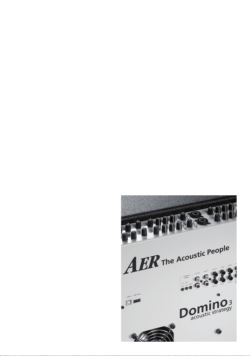
3. Co ntrols and Connections 5
3.1 Front Side 5
3.2 Rear Side 6
4. Starting up 7
4.1 Cabling and Switching-on 7
4.2 Level Adjustment 7
5. Functional characteristics 8
5.1 Mute 8
5.2 Equalization 8
5.3 Eects 8
5.4 Phantom-Power 9
5.5 Stereo-Simulation 9
5.6 Insert-Loop 10
5.7 Connecting AER-amps via Insert-Loop 11
6. Technical Specications 12/13
7. Circuit Diagram 14

3
1. Introduction
Welcome to B
Thank you for purchasing the Domino 3 of our
acoustic-line-series.
To obtain maximum enjoyment from your amplier
please read this manual carefully before using your
Domino 3.
Based on our Compact602-acoustic-system we have
developed the Domino 3 a 2x100-watt system
that combines the excellent tone of the Compact
with increased power and higher eciency.
The Domino 3 is – of course – dynamically controlled
and equipped with two parallel power-ampliers, two
8“-twin-cone loudspeakers, 1“-neodym tweeter for
additional headroom, 4 inputs with mute-option (in-
puts 3 and 4 with shared equalization), channel mute,
insert-link feature and AER-32/24-bit-digital-eects
with 16 presets.
Read on and have fun using your Domino 3!
4
2. Safety Instructions
The following guidelines shall help minimize the risk of injury through re or electric shock.
1. Carefully read these safety notes before you
use the device!
2. Keep these safety notes in a safe place.
3. Pay attention to all warnings, instructions and
additional texts on the unit.
4. This device was only designed for operation
under normal climatic conditions (temperate
climate).
5. Do not install or use your amp in close proximi-
ty to water or if you are wet yourself.
6. Do not subject your device to sudden and
severe temperature changes. This could cause
moisture condensation inside the unit, which
could damage it. In the event of moisture
condensation allow the device to dry out com-
pletely before use.
7. Use your amp in a safe place where nobody can
step on cables or trip over and damage them.
8. Pay attention to an unhindered air circulation
around the amp, never obstruct the air vents or
grilles.
9. Always pull the mains plug before cleaning
your amp or when left unused for a long period
of time. Use only a dry cloth for cleaning. Avoid
the use of detergents and do not let any liquids
seep into the unit.
10. Use only the right fuses with the same current
rating and trigger characteristic as replace-
ments. Never mend fuses! Pull the mains plug
before replacing a fuse. Should a fuse blow
again after a short while, the device needs to
be checked.
11. Never install your amp close to devices with
strong electromagnetic elds such as large
mains transformers, revolving machines, neon
illumination etc. Do not lay signal cables paral-
lel to power current cables.
12. There are no user-serviceable components
inside the unit. To avoid the risk of an electric
shock, the unit must not be opened. All main-
tenance, adjustment and repair works should
be carried out by qualied sta only. Any
unauthorized tampering will void the 2-year
warranty.
13. In keeping with the EMV regulations screened
cables with correctly tted connectors must be
used for all signal connections.
14. Always use an earthed power supply with the
correct mains voltage. If you are in doubt about
the power outlet ground, have it checked by a
qualied technician.
15. Cable up your amp only when it is powered o.
16. This device should be installed near the socket
outlet and disconnection of the device should
be easily accessible. The mains plug of the
powersupply shall remain readily operable.
Protect the power cord from being walked on
or pinched particularly at plugs, convenience
receptacles and the point where they exit from
the apparatus.
17. This product may cause permanent hearing
loss. Do not operate for long periods of time
at a high volume level or at any level that is
uncomfortable. If you experience any hearing
loss or ringing in the ears, you should consult
an audiologist.
18. The product should be located away from heat
sources such as radiators, heat registers or
other products that produce heat.
19. Do not place any open sources of re, like
candles, on the device.
20. Care should be taken so that objects do not fall
onto the device and liquids are not spilled into
the enclosure through openings. Ensure that
no objects lled with liquids, such as vases, are
placed on the device.
21. Do not place this device on an unstable
cart, stand, tripod, bracket or table. The
device may fall, causing serious injury to you
and serious damage to the device itself.
CAUTION
RISK OF ELECTRIC SHOCK
DO NOT OPEN
ATTENTION
RISQUE DE CHOC ELECTRIQUE
NE PAS OUVRIR
The lightning ash with
the arrow head symbol
within an equilateral
triangle is intended to alert the
user to the presence of unisolated
´dangerous voltage´ within this
product´s enclosure that may
be of sucient magnitude to
constitute a risk of electric shock
to persons.
The exclamation point
within an equilateral
triangle is intended to
alert the user to the presence
of important operating and
maintenance (servicing)
instructions in the literature
accompanying this product.

5
3. Controls and Connections
master
channels 1 – 4
effect
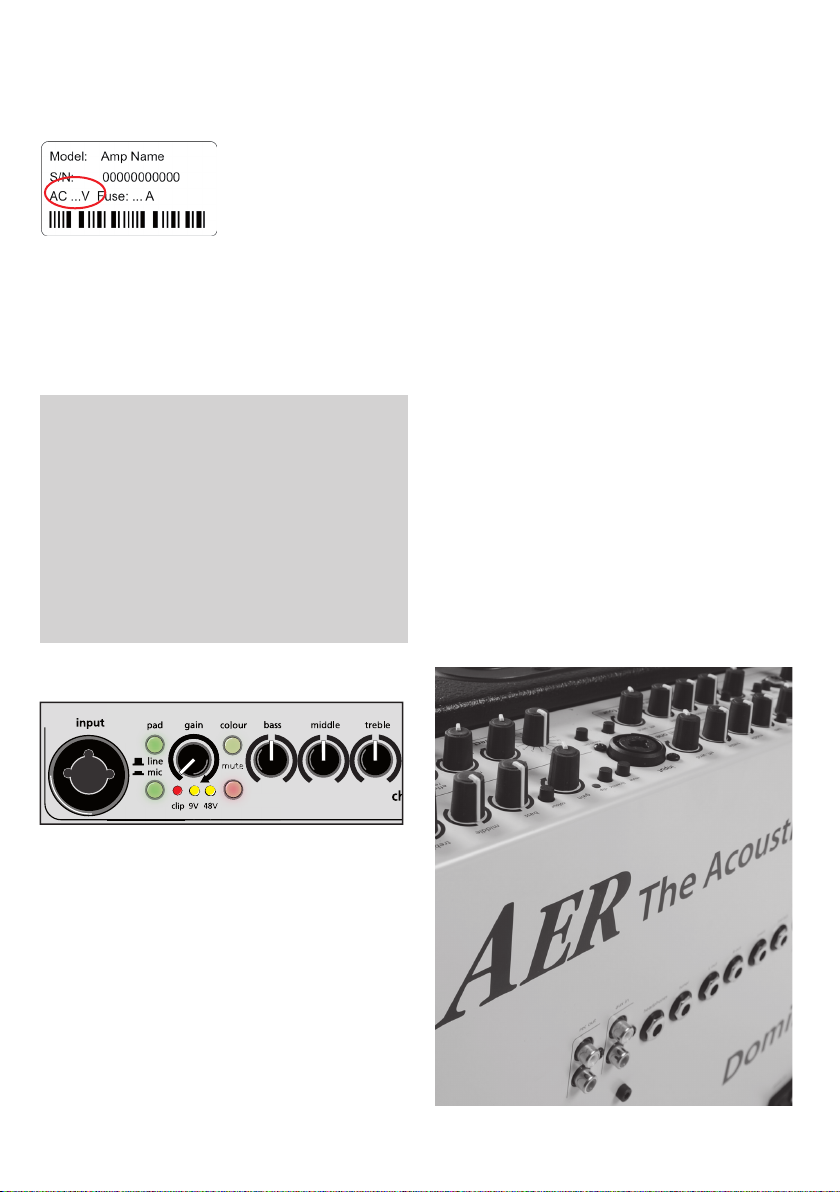
3.1 Front Side
1) input signalinput, Combijacket for 6,3 mm mono or XLR plugs
2) pad input sensitivity switch – attenuator deactivated, activated
3) line/mic signal source selector switch of the combo socket:
line (only via jackplug) for instruments (pickup) and other line level sources
mic (only via XLR-connector) for microphones
4) gain input level control
5) colour tone colour lter activation switch: deactivated , active
6) bass bass frequency control
7) middle middle frequency control
8) treble treble frequency control
9) eff. send eect level control
10) input signal input, 6,3 mm mono jack socket or XLR-male-connetor
11) pad input sensitivity switch – attenuator deactivated, activated
12) line/mic signal source selector switch of the combo socket:
line (only via jackplug) for instruments (pickup) and other line level sources
mic (only via XLR-connector) for microphones
13) gain input level control
14) colour tone colour lter activation switch: deactivated , active
15) mute channel mute switch: deactivated, active
16) bass bass frequency control
17) middle middle frequency control
18) treble treble frequency control
19) effect send eect level control
20) eff. select 1/2 Eect control for channel 1 and 2
21) eff. select 3/4 Eect control for channel 3 and 4
23) eff. level master level control for internal eects
22) aux in aux in level control
24) pre out input level control for L-out und R-out
25) master master level control
23
20
4x24
21x3.2
26x9
Ansicht von
außen
1216
315
414
513
612
7
11 8
10 9
1216
315
414
513
612
7
11 8
10 9
518
21
16
814
6
15
7
124
11
222
23 25
26
3
20
17
94 19
12
13
10
6
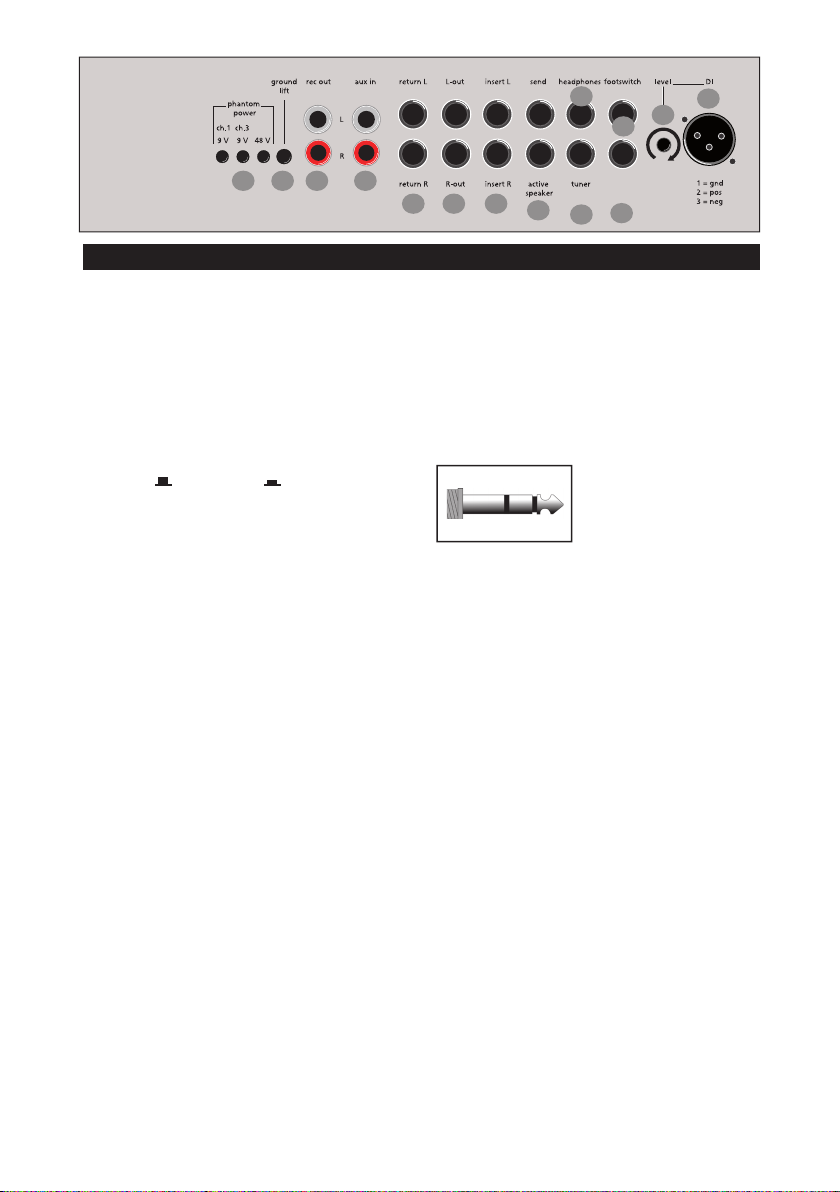
1) phantom power:
ch. 1, 9 V switch to activate 9-V-phantom-
power at chanal 1
ch. 1, 9 V switch to activate 9-V-phantom-
power at chanal 3
48 V switch to activate
48-V-Phantom-power
2) ground lift:
signal-/protective-ground disconnecting
switch: deactivated, acitve
3) rec out: stereo output with equalizer, eect,
stereo-reproduction of ext. eect, aux in and
stereo simulation (switchable), Cinch/RCA-
sockets (white = left channel, red = right
channel).
4) aux in: stereo input for additional signal
sources, e.g. CD-player, Cinch/RCA-sockets
(white = left channel, red = right channel)
5) return:
as part of the eect loop operates as signal
input from an external eect device (from
output of the eect device). The eect can be
switched on or o via footswitch.
6) L-out/R-out: stereo output with equalization,
eects, stereo-reproduction of external eect,
aux in and stereo-simulation (switchable),
6,3 mm jack socket.
7) insert: insert point, 6,3 mm stereo-jack-plug,
tip = send, ring = return, for serial looping of
eect-devices or for connecting AER-amps
with link-feature. (see para. 5.6, page 11)
3.2 Back Side
8) send:
is an output to connect to an external eect
device and in conjunction with return (input)
forms a loop here designed as an external
eect loop. The eect can be switched on or
o via footswitch.
9) headphones:
stereo-headphones socket
!!!
Warning: Only use
headphones with stereo
jackplugs in this output
socket!!!
10) tuner:
tuner output socket (mono, -10 dbV)
pre master
11/12) footswitch mute channel 1/2 + 3/4: Ste-
reo connector socket for a double-footswitch,
mute input 1/2 (tip = input 1, ring = input
2) resp. mute input 3/4 (tip = input 3, ring =
input 4).
13) DI level: signal output control to DI Output.
14) DI-out: signal output, symmetrcal,
XLR-female-socket, without equalization
and eects, pre master15)
15) power on: (not shown)
Combined mains switch with mains socket
and fuse holder. (s. Technical Data Mains Fuse)
tip = int. eff. ch 1
ring = int. eff. ch 2
footswitch
tip = int. eff. ch 3
ring = int. eff. ch 4
1 2 3 4
68
11
9
75
13
14
12
10
7
The clip-LED indicates an overload. A short icker is
of no danger to AER devices. During operation a short
icker can be accepted, to be on the safe side you
should reduce the gain slightly to achieve an optimal
and distortion-free performance.
Please bear in mind: The Domino2.A is equipped with
four inputs. Four individual gain-levels may boost the
input-signal of the eect-section and thus cause dis-
tortion. This distortion can only be heard and in this
case it is imperative, to reduce the gains to elminitate
the distortion.
With the line/mic-switch you can adjust your ampli-
er to your signal-sources (guitar pickup, microphone
etc.). The attn.-switch (attenuator de-/activation),
as well as gain-control and line/mic-switch, helps
with the signal-matching. Start without attenuator
(switch not pressed). Should the input-signal be too
strong and you can’t avoid clipping even by reducing
the gain-control, then activate the attenuator
(switch pressed).
Finally set the desired overall volume level with the
master level control.
4. Starting up
4.1 Cabling and switching on
Before connecting to mains, please ensure that your
local mains voltage is
suitable for the voltage
of the device (e.g. 120V in
the USA, 230V in Europe).
The relevant specs and
safety symbols are prin-
ted on the rear side of the unit.
Connect all cables according to your application and
switch the amplier on. The green power control LED
indicates operational readiness.
4.2 Level Adjustment
Note: Level adjustment
By setting the level correctly we mean the signal level
in one or several devices in a signal chain is neither
too high nor too low. This applies equally to all cir-
cuits in a complete circuit design (EQs, preamps etc.)
Consequently, care must be taken that no part of the
circuit is overloaded or that distortion is unintentio-
nally added to the signal.
We have carefully designed the circuit to achieve this
objective whilst also providing controls for„manual“
intervention.
First ensure, that the master level control is zeroed
(over to far left), so that when you are setting the
sound level, the signal passes through the electronics
only and does not reach the loudspeaker. By pressing
the high-/low- (attn.) resp. line-/mic-switches you
can adapt the amplier to your signal sources (guitar
pickups, microphone etc).
Turn the gain control clockwise until the red clip
indicator ashes momentarily when playing with a
strong attack. Thus you make sure that your signal
source (e.g. instrument) provides the input-stage of
the amplier with the necessary input.
23
20
4x24
21x3.2
26x9
Ansicht von
außen
1216
315
414
513
612
7
11 8
10 9
1216
315
414
513
612
7
11 8
10 9

8
5. Functional characteristics
5.1 Mute
The mute switch turns the appliance to mute as requi-
red. The function can also be activated by a standard
footswitch (on/o switch).
5.2 Equalization
The triple-band equalizer of your Domino2.A provides
you with an active and high quality sound interaction
tool that supports the natural tone of instruments and
voice whilst simultaneously oering you the possibili-
ty of a controlled accentuation.
With all controls in mid position the lters are set to
produce a very pleasing and natural sound impression
that you can„colour up“ by using the colour lter with
the eect of lowering the mids and lifting the trebles
(-3 dB at 700 Hz, +10 dB at 8kHz). The tone becomes
more open and light and is especially suited for nger-
picking techniques.
The equalization can support or soften the eect of
the colour lter and allows a dierentiated mids-
accentuation.
A: with colour-lter (switch pressed)
reduce treble to soften possible sharpness
B: without colour-lter (switch not pressed)
boost treble to brighten the sound
colour bass middle treble
Note:
The active equalization of the Domino 3eects the
signal adjustment. If you spot an intensied ickering
of the clip indicator, level the signal level with the gain
control (s. 4.2 Level adjustment).
5.3 Eects
The Domino 3 has a built-in (internal) digital
32/24-bit-AER-eect processor, with the select-switch
you can choose between 16 diverging presets (s.
chart below).
The return-control determines the intensity of the
internal eects (left stop = no eect), the eff. send-
controls level the ratio of eect and original signal
per channel.
Progr.-No. Description
1 ambience: short
2 ambience: medium
3 ambience: long
4 reverb: short
5 reverb: medium-short
6 reverb: medium
7 reverb: long
8 reverb: very long
9 delay: 100ms
10 delay: 320ms short
11 delay: 320ms long
12 chorus
13 delay (410ms) with reverb-portion short
14 reverb with delay-portion (410ms) long
15 chorus with reverb-portion
16 reverb with chorus-portion
Furthermore an additional eects unit (external
eect) may be connected to the Domino 3. For this
purpose use the send and return sockets on the rear
side of the amplier (send goes to input, return to
the output of the external eects device). The intensi-
ty of the eect is adjusted at the external eects unit.
colour bass middle treble

9
5.4 Phantom power
Microphones requiring 48V phantom power can be
directly connected to the XLR sockets of channels 2
and 3/4. The phantom power can be switched on and
o via the 48V-switch.
The jack sockets of channel 1 and 3/4 can additi-
onally be supplied 15V-Phantomspeisung by an
internal jumper.
Please note: For these alterations the device must
be opened, therefore only qualied service person-
nel may carry out the modications concerning the
activation of phantom power.
5.5 Stereo-Simulation
The Domino2.A is mono – thus L-out and R-out are
carrying the same output-signal. You can use these
sockets to connect additional active AER fullrange-
systems (e.g. AG 82, CX 8, AS Q8, AS 281), whose levels
are adjusted by the pre master-control independent
of the overall volume (master) of your Domino2.A. By
activating the stereo-simulation (stereo sim.-switch
pressed), a stereo-like, wider sound impression is
generated.
On stage (Domino 3 as monitor) the sound remains
unchanged..
P.S. For questions or suggestions contact us:
General Note:
Use of 48V or 24V phantom power
(Phantom power = remote supply, here: powering
an audio device via the connected audio line)
Turn on the phantom power only if the unit con-
nected to the XLR sockets of channels 2 and 3/4 is
designed to handle it!
In general, suitable units are e.g. condenser
microphones, active DI-boxes and other special
audio devices, whose power supply is drawn from
the phantom power. Such devices are also labelled
accordingly; please heed the permissible power
consumption (max.10mA).
High-quality dynamic microphones with a balanced
signal need no phantom power, but can handle it
anyway.
Other devices, which have not been designed
explicitly for phantom power operation, can suer
from considerable malfunctions and damage may
result as well.
Examples of devices that may be damaged by
incorrect application of phantom power include:
Low-cost dynamic microphones with a mono jack-
plug (unbalanced signal) that were tted afterwards
with an XLR connector.
Audio devices with a balanced XLR output (e.g.
DI-boxes, eects devices, instrument preamps with
a DI output etc.) which are not protected against
phantom power applied to their XLR output. (The
DI connectors on AER products are protected
against applied phantom power.)
Other audio devices (such as preamps, eects
pedals etc.) whose unbalanced line output was
replaced by an XLR socket.
If in doubt please consult the manufacturer of the
device you are using.
10
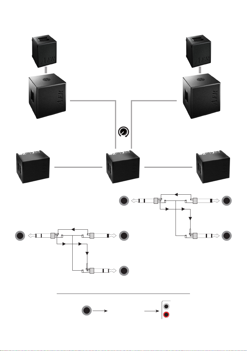
5.6 Insert
The insert-loop is an in-/output on a stereo-socket to
link dierent eect-devices (EQ, compressor etc.) in serial
mode with tip = send (input) and ring = return (output).
This conguration allows several more applications,
such as:
1. use as additional line-output
2. use as additional line-input
3. link between two or more AER-amps with insert-
feature (AG8, Domino, Compact ClassicPro)
For each of these applications you’ll need the appropriate
cable connection, e.g. use as line-output: stereo-jack
(tip and ring = hot, sleeve = ground) to mono-jack.
The particular AER-link-application (s. no. 3 - link bet-
ween AER-amps) is represented on page 11. In link-ope-
ration it is assured, that the signals of all connected amps
are hearable on all devices, even with dierent eect
settings. You just have to be aware, that the dierent
levels depend on each other.
This setting (in combination with active loudspeakers,
pre master-function) works as a complete and easily
operated reinforcement/monitor system.
11
L-out R-out
tip
tip
tip
ring
ring
tip
tip
tip
ring
ring
insert
insert
line out
return
line out
return
send
external eect
In case of occupied return-socket due to insert operation, you can still
loop an external eect using the send- and aux-in-sockets.
Domino2.A
power on
1 = gnd
2 = pos
3 = neg
return
send
DI-out
headphones tuner L-out R-out insert line-out
effect on/off mute channel 3/4
mute channel 1/2
rec out
aux in
ext. effect footswitch
C A UT I O N
RISK OF ELECTRIC SHOCK
DO NOT OPEN
AT T E N T I O N
RISQUE DE CHOC ELECTRIQUE
NE PAS OUVRIR
Made in Germany by B
20120705
clipattn. colourmute
line/micmute
input input
input
gain
gain
bass middle treble eff. send clipline/mic colourmute gain bass middle treble eff. send
clipattn. colourmute 48V stereo sim. power
input gain bass middle treble eff. send select return aux
return effect 2
return
pre
master
master
channel one
channel three + four
channel two
effect master
Domino2.A
12
3
4
5
6
7
8
9
10
11
12
13
14
15
16
20120705
5.7 Example for the linking of AER-amps via the insert connection
PA-System PA-System

12
6. Technical Specications Domino 3, part 1
Inputs (notes 1, 2)
Inputs, channels Combo socket, XLR + jack ¼”(6.35 mm)
1 – 4 Line mode
High impedance, unbalanced jack
input for instruments (pick-ups) and
line-level sources
Sensitivity: 26 mV (–32 dBV)
Pad switch (attenuator): –10 dB
Impedance: 1 Meg
Equivalent input noise,
A-weighted: 1.6 µV (–116 dBV)
Phantom power: +9 V DC at ring of jack
sockets in Ch. 1 and Ch. 3, switchable
per channel (note 4), max. 100 mA (all
channels total), overload protected
Mic mode
XLR (balanced), stereo jack (balanced),
or mono jack (unbalanced) input
Sensitivity: 7.5 mV (–43 dBV)
Pad switch (attenuator): –19 dB
Impedance (balanced): 1.7 k
Equivalent input noise,
A-weighted: 0.3 µV (–130 dBV)
Voice lter: –4 dB at 450 Hz
(referred to 10 kHz)
Phantom power: 48 V, with common
on/o
switch for all four channels (note 4)
Clip indicator: Headroom 6 dB
Return Stereo return from external parallel
eect loop
2 x mono jack, ¼” (6.35 mm, left/right
Sensitivity: 375 mV
Routing: stereo to speakers,
headphones, rec out, and L/R-out;
mono (L+R) to DI out
Aux in Auxiliary stereo input (e.g.,
for CD player)
Level adjustable
Cinch (RCA) sockets (left/right)
Sensitivity: 375 mV
Routing: stereo to speakers,
headphones, rec out, and L/R out;
mono (L+R) to DI out
Outputs (note 3)
Tuner Tuner output, not aected by
mute switch
Mono jack, ¼” (6.35 mm)
Output voltage: 360 mV
Headphones Headphones output. When connected,
internal speakers are muted.
Stereo jack, ¼” (6.35 mm)
Output power:
max. 2 x 100 mW / 32 ohms
Input sensitivity for
2 x 50 mW / 32 ohms:
30 mV at line input (any channel)
Caution: For stereo headphones with
stereo jack plug only.
Do not connect mono plugs.
Active speaker Mono (L+R) output post-master,
suitable for active extension speaker
Mono jack, ¼” (6.35 mm)
Output voltage: 1.4 V
Activates 100 Hz low-cut lter for
internal speaker if plugged in.
L/R-out Stereo line output after tone controls,
with aux in and eects
Level adjustable by pre out
2 x mono jack, ¼” (6.35 mm, left/right)
Output voltage: 0…1.4 V
Rec out Recording output after tone controls,
with aux in and eects
Cinch (RCA) sockets (left/right)
Output voltage: 1.4 V (note 4)
DI Balanced XLR output before master,
after tone controls, with aux in and
eects (note 4)
Level adjustable
Output voltage: 0…145 mV
Send Send for parallel eect loop
Mono jack, ¼” (6.35 mm)
Output voltage: 710 mV (note 4)
USB lamp DC output for a lamp
Data lines are not connected.
Output voltage: 5 V DC, max. 200 mA
Insert points
Insert L/R Stereo insert point after master volume
2 x stereo jack (L/R), ¼”(6.35 mm)
Tip = send, ring = return
Output voltage: 1.4 V
Tone controls (all channels)
colour +10 dB at 8 kHz, –3 dB at 700 Hz
bass ±8 dB at 100 Hz, shelf type
middle ±4 dB at 650 Hz
treble ±9 dB at 10 kHz, shelf type
Eects
Internal eect AER 32-bit digital eect processor
with 16 factory presets
Two independent, simultaneous
eects (one for channels 1 and 2, and
one for channels 3 and 4).
USB interface and PC software for
creating userdened settings

13
6. Technical Specications Domino 3, part 2
External eect Parallel eect loop
(see send and return)
Power
Power amp 2 x 100 W / 4 ohms,
discrete bipolar transistor design
Dynamic range: 100 dB (A-weighted,
see note 2)
Limiter threshold 2 x 85 W
Analog signal Subsonic lter, low distortion
processing RMS limiter
Speaker system Two 8” (200 mm) twin cone
full-range speakers,
bass reex enclosure
Mains power Mains voltage (depending on model):
100, 120, 230, or 240 V AC, 50–60 Hz.
Power consumption: max. 420 W
Mains fuse 5 x 20 mm
Slow 3.15 A for 230 and 240 V models
Slow 6.3 A for 100 and 120 V models
General
Cabinet 15 mm (0.6”) nnish birch plywood
Finish Waterbased acrylic, black spatter nish
Dimensions 365 mm (14.37“) high
420 mm (16.54“) wide
300 mm (11.81“) deep
Weight 16 kg (35.3 lbs)
Notes:
1. Input sensitivity
Input sensitivities refer to 2 x 85 watts into 4 ohms, full
gain and master settings, neutral tone control settings,
and 1 kHz sine-wave test signal.
2. Noise and dynamic range
Equivalent input noise voltage was obtained by measuring
noise voltage at speaker output and dividing by the
eective voltage gain of the amplier. Full gain and master
settings, neutral tone control settings, input shorted,
measuring bandwidth 20 Hz – 20 kHz.
Dynamic range: Range between output signal at limiter
threshold and A-weighted output noise with master
volume in zero position.
3. Output levels
Output levels refer to 50 mV / 1 kHz sine-wave test signal
at channel 1 input in line mode, full gain and master
settings, and neutral tone control settings.
4. Options
The following options can be activated by jumper settings.
9 V phantom power can be enabled for channels 2 and
4 if required. (Not recommended generally, because only
a common switch will be available for channels 1/2, and
channels 3/4 respectively)
48 V phantom power can be disabled for each
of the four channels.
DI output can be changed from post-equalizer to
pre-equalizer (tone controls) for each channel, and
disconncted from aux in, internal, and external eects.
Send level can be made dependent on e. send controls
for each channel.
Rec out level can be made dependent on pre out
control. 0 dBV = 1 V
Specications and appearance subject to change without
notice.
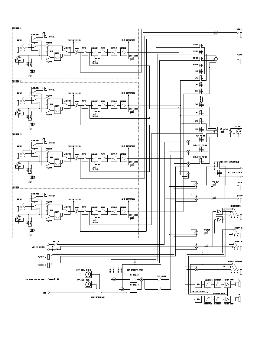
14
7. Circuit diagram Domino 3

15
notes

www.aer-amps.com
DOMINO 3-150225-GB
Other manuals for domino 3
2
This manual suits for next models
1
Table of contents
Other AER Musical Instrument Amplifier manuals


