Aerfast TS55-AC User manual

MODEL: TS55-AC

WARNING Read all safety warnings and instructions. Failure to follow
the warnings and instructions may result in electric shock, fire and/or serious
injury.
Save all warnings and instructions for future reference.
The term ″power tool″ in the warnings refers to your mains-operated
(corded) power tool or battery-operated (cordless) power tool.
1) Work area safety
a) Keep work area clean and well lit. Cluttered or dark areas invite
accidents.
b) Do not operate power tools in explosive atmospheres, such as in
the presence of flammable liquids, gases or dust. Power tools create
sparks which may ignite the dust or fumes.
c) Keep children and bystanders away while operating a power
tool. Distractions can cause you to lose control.
2) Electrical safety
a) Power tool plugs must match the outlet. Never modify the plug in
any way. Do not use any adapter plugs with earthed (grounded)
power tools. Unmodified plugs and matching outlets will reduce risk of
electric shock.
b) Avoid body contact with earthed or grounded surfaces such as
pipes, radiators, ranges and refrigerators. There is an increased risk
of electric shock if your body is earthed or grounded.
c) Do not expose power tools to rain or wet conditions. Water
entering a power tool will increase the risk of electric shock.
d) Do not abuse the cord. Never use the cord for carrying, pulling
or unplugging the power tool. Keep cord away from heat, oil,
sharp edges or moving parts.
Damaged or entangled cords increase the risk of electric shock.
e) When operating a power tool outdoors, use an extension cord
suitable for outdoor use. Use of a cord suitable for outdoor use
reduces the risk of electric shock.
f) If operating a power tool in a damp location is unavoidable, use
a residual current device (RCD) protected supply. Use of an RCD
reduces the risk of electric shock.
1BOPERATING INSTRUCTIONSOPERATING INSTRUCTIONS
AUTOFEED SCREW DRIVER MODEL TS55-AC
1

NOTE The term ″residual current device (RCD)″ may be replaced by
the term ″ground fault circuit
interrupter (GFCI)″ or ″earth leakage circuit breaker (ELCB)″.
3) Personal safety
a) Stay alert, watch what you are doing and use common sense
when operating a power tool. Do not use a power tool while you are
tired or under the influence of drugs, alcohol or medication. A
moment of inattention while operating power tools may result in serious
personal injury.
b) Use personal protective equipment. Always wear eye
protection. Protective equipment such as dust mask, non-skid safety
shoes, hard hat, or hearing protection used for appropriate conditions
will reduce personal injuries.
c) Prevent unintentional starting. Ensure the switch is in the
off-position before connecting to power source and/or battery
pack, picking up or carrying the tool.
Carrying power tools with your finger on the switch or energising power
tools that have the switch on invites accidents.
d) Remove any adjusting key or wrench before turning the power
tool on. A wrench or a key left attached to a rotating part of the power
tool may result in personal injury.
e) Do not overreach. Keep proper footing and balance at all times.
This enables better control of the power tool in unexpected situations.
f) Dress properly. Do not wear loose clothing or jewellery. Keep
your hair, clothing and gloves away from moving parts. Loose
clothes, jewellery or long hair can be caught in moving parts.
g) If devices are provided for the connection of dust extraction and
collection facilities, ensure these are connected and properly used.
Use of dust collection can reduce dust-related hazards.
4) Power tool use and care
a) Do not force the power tool. Use the correct power tool for
your application. The correct power tool will do the job better and
safer at the rate for which it was designed.
2

b) Do not use the power tool if the switch does not turn it on and
off. Any power tool that cannot be controlled with the switch is
dangerous and must be repaired.
c) Disconnect the plug from the power source and/or the battery
pack from the power tool before making any adjustments,
changing accessories, or storing power tools. Such preventive
safety measures reduce the risk of starting the power tool accidentally.
d) Store idle power tools out of the reach of children and do not
allow persons unfamiliar with the power tool or these
instructions to operate the power tool.
Power tools are dangerous in the hands of untrained users.
e) Maintain power tools. Check for misalignment or binding of
moving parts, breakage of parts and any other condition that
may aect the power tool’s operation. If damaged, have the
power tool repaired before use. Many accidents are caused by
poorly maintained power tools.
f) Keep cutting tools sharp and clean. Properly maintained cutting
tools with sharp cutting edges are less likely to bind and are easier to
control.
g) Use the power tool, accessories and tool bits etc. in
accordance with these instructions, taking into account the
working conditions and the work to be performed. Use of the
power tool for operations dierent from those intended could result in
a hazardous situation.
5) Service
a) Have your power tool serviced by a qualified repair person using only
identical replacement parts. This will ensure that the safety of the power
tool is maintained.
Hold power tool by insulated gripping surfaces, when
performing an operation where the fastener may contact hidden wiring or
its own cord. Fasteners contacting a ”live” wire may make exposed metal parts
of the power tool ”live” and cold give the operator an electric shock.
3

△,!WARNING
Operational Precautions
General Safety Instructions
1. Consider work area environment. Do not expose tools to rain. Do not
use tools in damp or wet locations:Keep work area clean and well lit. Do
not use tools in the present of flammable liquids or gases.
2. Guard against electric shock. Avoid body contact with earthed or
grounded surfaces.
3. Keep children away. Do not let visitors touch the tools or extension cord.
All visitors should be kept away from work area.
4. Store idle tools. When not in use, tool should be stored in a dry locked
up place, out of reach of children.
5. Do not force the tool. It will do the job better and safer at the rate for
which it was intended.
6. Stay alert. Watch out what you are doing:Use common sense. Do not
operate tool when you are tired. Check damaged parts. Before further
use of the tool, a guard or other part is damaged should be carefully
checked to determine that it will operate properly and perform its
intended function.
7. Check for alignment of moving parts, blinding of moving parts, breakage
of parts, mounting and any other condition that may affect its operation.
8. A guard or other parts that is damaged should be properly repaired or
replaced by an authorized service center unless otherwise indicated in
this instruction manual. Have defective switches replaced by an
authorized service center. Do not use tool if switch does not turn it on.
9. To ensure the designed operational integrity of power tools, do not
remove installed cover or screws.
10. Use your tool at lower input than specified on the nameplate, otherwise,
the finish may be spoiled and working efficiency reduced by motor
overload.
11. Do not wipe plastic parts with solvent. Solvents such as gasoline,
thinner, benzene, carbon tetrachloride, alcohol, ammonia and oil
containing chloric annex may damage and crack plastic parts. Do not
wipe them with such solvent. Wipe plastic parts with a soft cloth lightly
dampened with soap water.
12. Dress properly. Do not wear loose clothing or jewelry. Contain long hair
keep your hair, clothing, and gloves away from moving parts.
13. Use safety equipment. Always wear eye protection, non-skid safety
shoes, hard hat, or hearing protection.
14. Do not overreach. Proper footing and balance enables better control of
the tool in unexpected situations.
4

△,!WARNING
1.
To ensure the designed operational integrity of power tools, do not
remove installed cover or screws.
2.
Use your tool at lower input than specified on the nameplate, otherwise,
the finish may be spoiled and working efficiency reduced by motor
overload.
3.
Do not wipe plastic parts with solvent. Solvents such as gasoline,
thinner, benzene, carbon tetrachloride, alcohol, ammonia and oil
containing chloric annex may damage and crack plastic parts. Wipe
plastic parts with a soft cloth lightly dampened with soap water.
4.
Use clamps or other practical way to secure and support the work piece
to a stable platform. Holding the work by hand or against your body is
unstable and may lead to a loss of control.
Product Safety Instructions
5.Use only accessories that are recommended by the manufacturer for
your model. Accessories that may be suitable for one tool may create a
risk of injury when used on another tool.
Specific Safety Rules and/or Symbols
--------Recycle
--------Do Not Throw In Garbage
------Class II Tool
V--------Volts
a.c.------Alternating Current Hz-------Hertz
W--------Watts
mm------Millimeter
kg-cm--Kilograms Per Centimeter
kg-------Kilograms
d.c. -----Direct Current
ft-lb------Foot-Pound
/
min-----Revolutions or Reciprocations Per Minute
5

View of the Major Components
Reverse Button
Forward/Reverse Rod
Main Switch
Conduction Ass’y
Power Cord
Carbon Brush Panel
Anti-slip Pad
Depth Control Knob
Screw Length Adjust Button
Specifications
Model No. TS55-AC
Voltage 220V a.c.
No-Load Speed 4200 r.p.m(/min)
Max. Torque 80 kg-cm/7.8 N-m/5.8ft-lb
Tool Weight 1.9kg
Volume L430 x W80 x H190mm
Fastener Range 25-55 mm length
Bit Spec 1/4” x 173Lmm
Quick Release Button
6

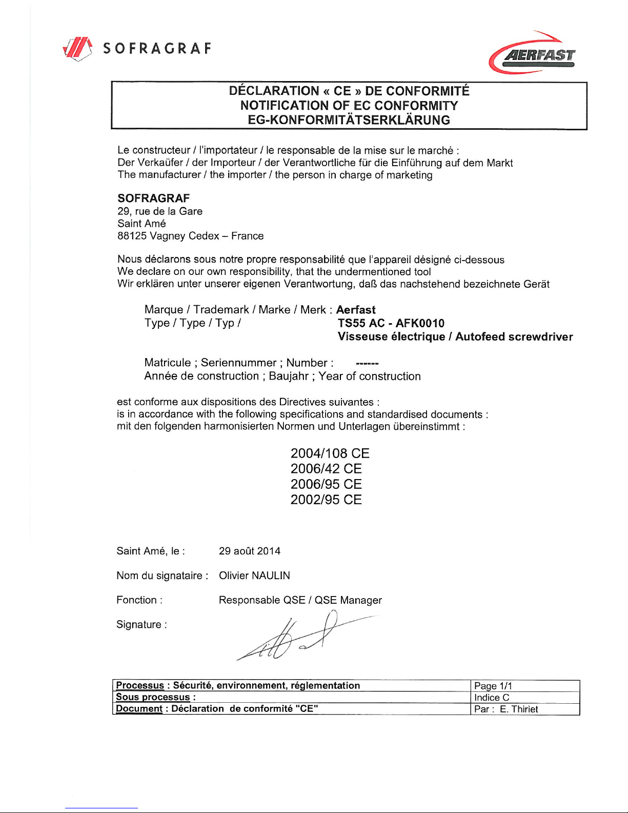
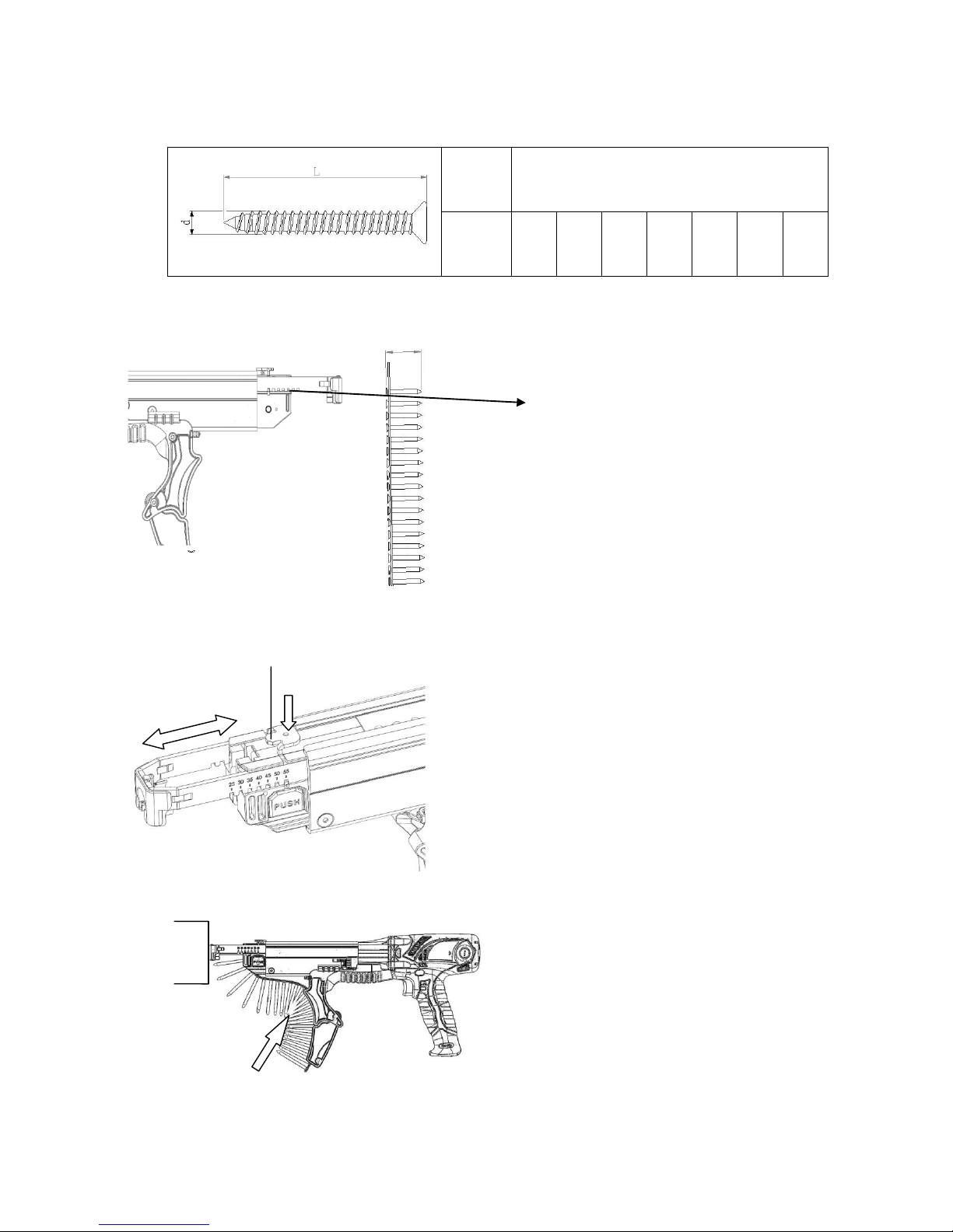
2BStrip Installation
1.Check the scale of the adjust is
totally consistent with length of the
screw.
2.Press the screw length adjust knob
for the correct length of the screw.
Release the knob when the auto feed
assembly has adjusted to the proper
position. Please adjust the length of
screw first. Do not adjust the length
when the collated screw is on.
This tool can be used in the following screw sizes.:
d(mm)
Φ3.5~Φ4.5mm
(#6~#8)
L(mm)
25
30
35
40
45
50
55
3. Feed the strip into the strip guide.
Screw Length
Screw Length Adjust Knob
Scale
Press
7

Tool Operation
4. Move the strip forward until the
2nd empty slot is aligned with
the bit. This will allow for the
proper strip advancement once
the nosepiece is depressed.
2. Whenever possible, hold the
tool at a right angle to the
work surface.
1. Make sure the forward/reverse
rod direction ( )。
Forward/Reverse Rod
(2)
3.
(1)Pull the main switch to start
the motor.
(2)Press the conduction,with
constant force, against the
work surface.
Do not remove the tool from
the work surface until the
clutch disengages and the
bit stops rotating, signaling a
fully driven screw.
(1)
Main Switch
8
Depth Control Knob
6. This tool has a depth sensing
clutch.When the screw is
countersunk to the pre-set
depth,it automatically
disengages and makes a
click or racheting sound. This
is normal and signals
completion of the drive.
4.Continue to allow the motor
to run.The next screw will be
automatically fed into place
when the tool is depressed
against the work surface.(3)
5. The depth display shows the
depth level. Adjust the depth
control knob for appropriate
depth. Please do not adjust the
depth control knob when the
depth display shows the
maximum level.
(3)
Depth Display
9
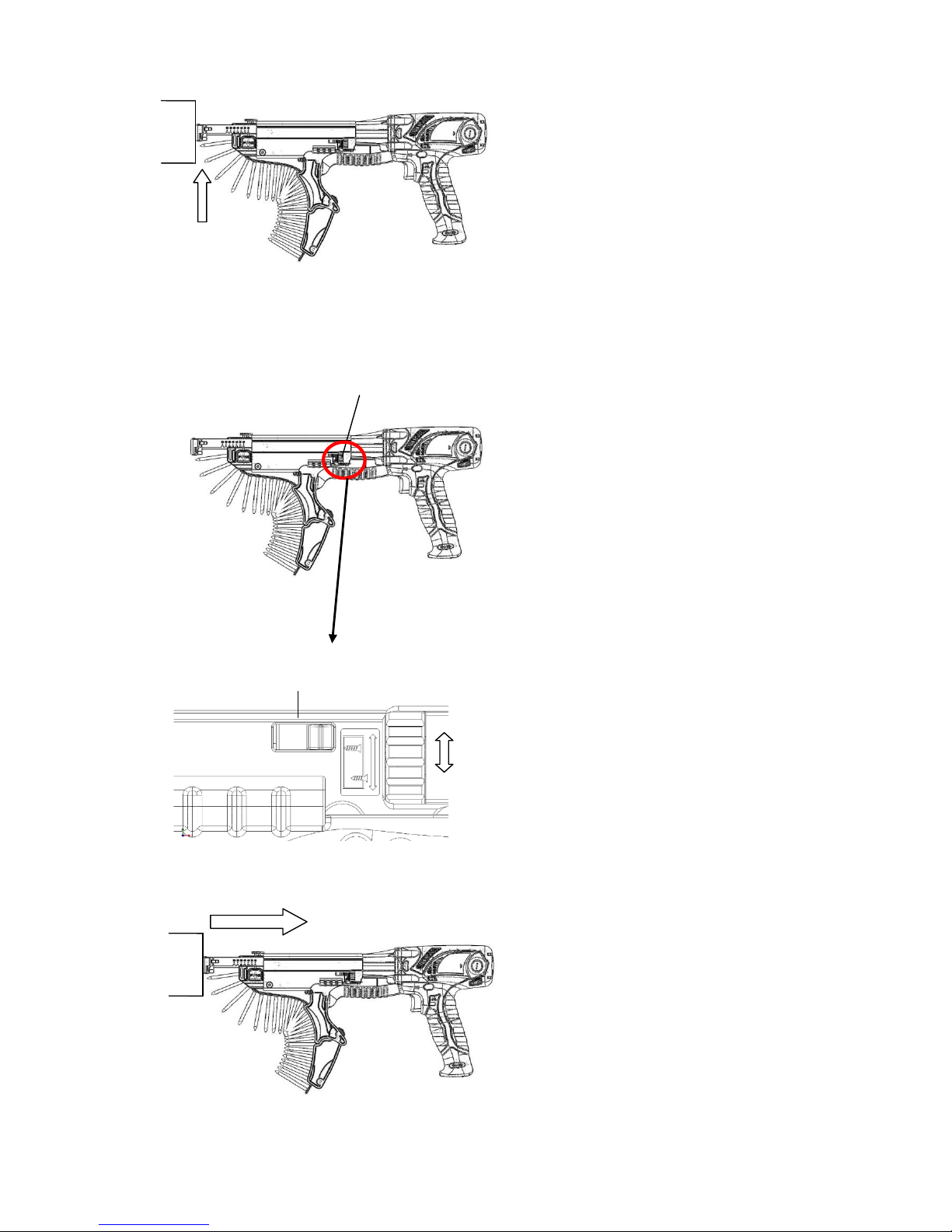
To Remove the Screws
Replaceable Non Slip Pad
Reverse direction
Reverse knob
Press
1.
(1)Remove the strip, pull it through
from the top of the nosepiece.
Pull the collated screw upward
for removing.When the screw
is out of position or stuck, push
the reverse knob while pulling
the collated screw downward at
the same time.
Push the forward / reverse rod
to reverse side ( ).
Depress nose piece while
inserting bit into screw.
(2)Maintain forward pressure on
tool.
(3)Pull the main switch to start
motor. Continue operation until
screw is completely
disengaged.
(3)
Main Switch
Forward /Reverse Rod
(2)
(1)
1.The non slip pad is self
replaceable if damaged or
dirty.
10
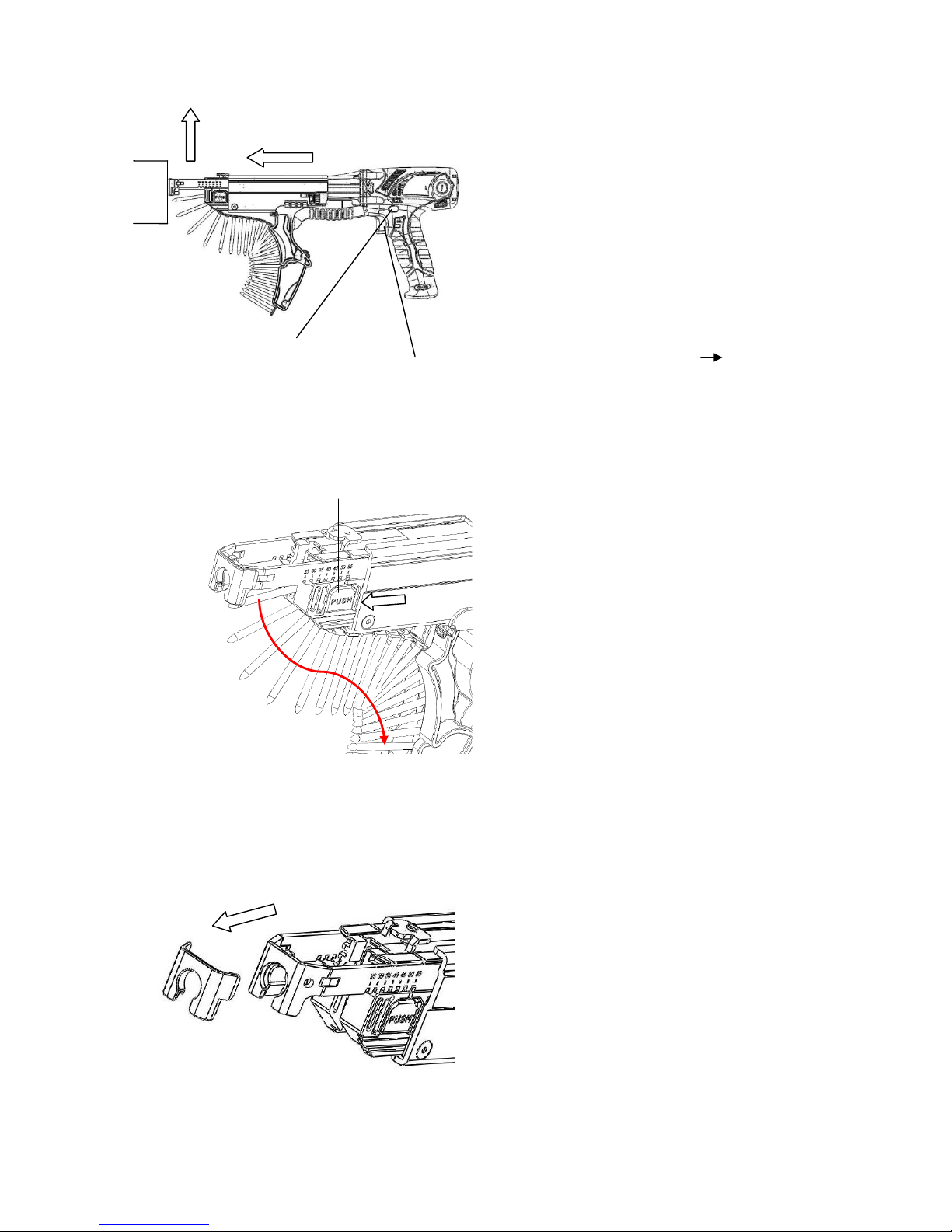
Change the Driving Bit
Note: Use the bit provided by the manufacturer.
1.
(1) Push the quick release button
backward first.
(2) then press down to loose
conduction ass'y.
2. Remove conduction
ass’y.
3. Pull the ring-pull and
replace the bit.
After replacement ﹐
assemble conduction
ass’y and lock in
screw.
Conduction Ass’y
Bit
Ring-Pull
(1) (2)
11

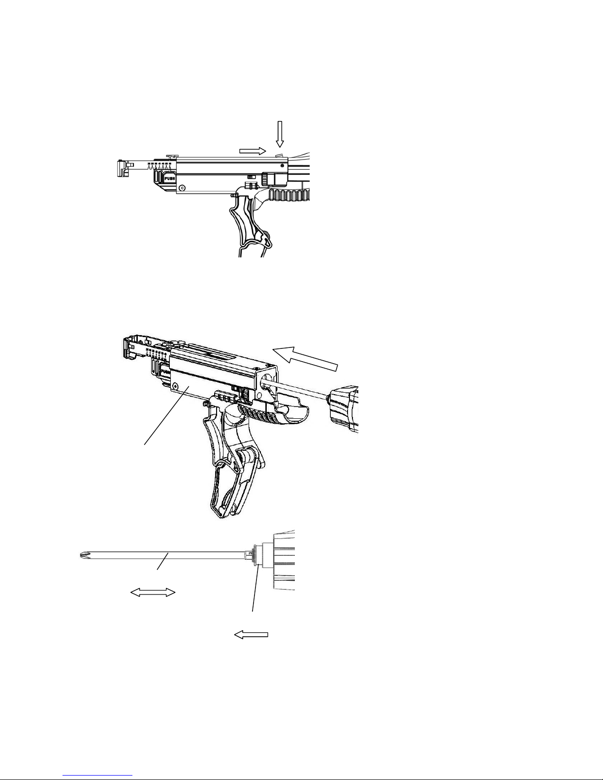
Installing Extended Rod Ass’y
1.. Remove conducti
ass’y and bit.
Conduction Ass’y Bit
3.
(1) Push the ring backward.
(2) Inject the bit.
2.
(1) Pull the ring-pull.
(2) Inject the extended
spindle.
(3) Inject the extended
rod.
※Pull the ring-pull of
the extended rod
can separate the
extended rod.
(2) (1)
Bit Ring
Ring-pull
(2) (1)
(3)
Extended Rod
Ring-pull
Conduction Ass’y
Extended Rod
Handle
4.. Inject the conducti
ass’y .
The handle can be
adjusted 360 degrees,
based on the user's setting
(to tighten: clockwise/ to
loose: anti-clockwise)
Extended Spindle
12
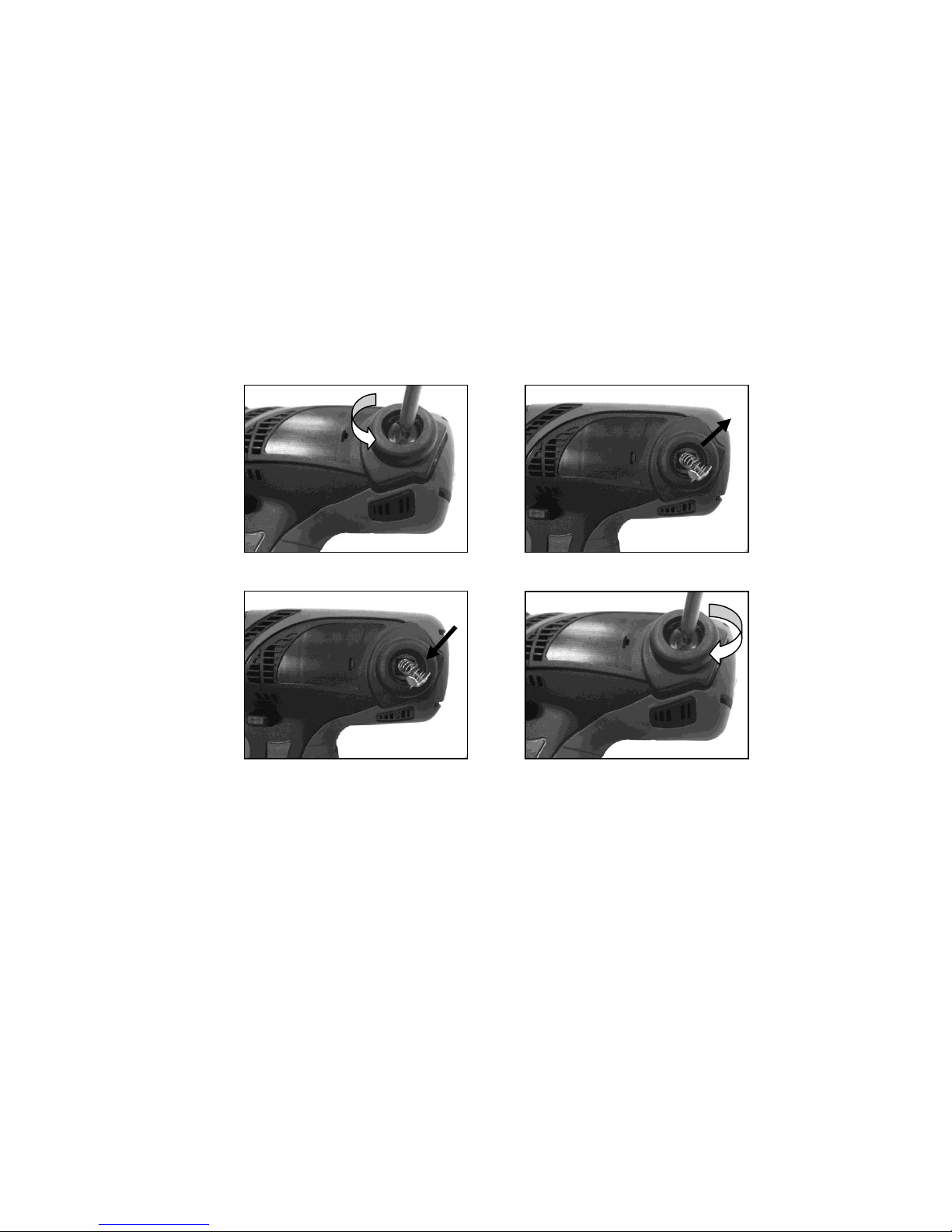
Replaceable Carbon Brush
1. Replace the new carbon brush, while the motor is not rotated and the
carbon brush is run out.(Change the new motor after the carbon brush has
been replaced 2~3 times)
2. Replacement procedure is as follows:
Loose the carbon brush panel counterclockwise by using slotted
bit.(Fig.1).
Take out the carbon brush ( Fig.2 ).
Put the new carbon brush and carbon brush panel back into the housing
in proper order. (Fig.3)
Lock the carbon brush panel back clockwise by using slotted bit. (Fig. 4)
Caution
Always be sure that the machine is switched off and is unplugged from the
power outlet removed before carrying out any work on the machine.
To maintain product safety and reliability, repairs, maintenance or adjustment
should be carried out by an authorized service center.
Fig.3
Fig.1
Fig.2
Fig.4
13

PRECAUTION
Lire ce manuel utilisateur avant d’utiliser la machine. Une mauvaise utilisation
pourrait entrâiner des risques de blessure.
Conserver ce manuel pour un éventuel besoin future.
Les termes “appareil “ ou « machine » ou « outil » employé ci-après
désigne la visseuse automatique.
1) Zone de travail
a) Garder la zone de travail propre, éclairée correctement et dégagée.
b) Ne pas utiliser l’outil en atmosphère potentiellement explosive,
comme en présence de liquide ou gaz inflammables.
Un appareil électrique peut en effet produire des étincelles.
c) Tenir les enfants et les personnes non nécessaires au chantier à
distance.
2) Sécurité électrique
a) La fiche électrique doit être compatible avec la prise réseau
disponible. Ne jamais modifier une prise électrique.
c) Ne pas exposer l’appareil à la pluie ou le plonger dans l’eau. De
l’eau entrant dans un appareil électrique accroît le risque de chocs
électriques.
d) Ne jamais détériorer le cordon. Ne pas utiliser le cordon pour porter,
tirer ou débrancher l’appareil du réseau électrique. Préserver le cordon
de la chaleur, des produits pétroliers, angles vifs coupants ou pièces
en mouvement.
e) En cas d’utilisation en extérieur, utiliser une rallonge électrique
adaptée à une telle utilisation.
3) Sécurité individuelle
a) Rester vigilant et attentif avec un outil en main.
b) Porter tout EPI (Equipement de Protection Individuel) requis par le
type de travail effectué.
1
INSTRUCTIONS UTILISATEUR TS55-AC
1BOPERATING INSTRUCTIONS
Visseuse automatique 230V pour vis en bandes.

c) Prévenir toute mise en route intempestive de l’outil.
S’assurer que l’interrupteur est en position « coupé » avant de
connecter l’appareil à la source d’énergie.
Porter un appareil avec le doigt sur la gâchette augmente le risque
d’accident.
d) Retirer toute clé ou outil de l’appareil avant la mise en route. Un outil
resté en place sur une partie tournante de l’appareil pourrait présenter
un danger pour les personnes présentes aux environs.
e) Garder l’équilibre et de bons appuis en toutes circonstances.
f) Porter une tenue adaptée au travail à effectuer. En présence de
partie rotative, veiller à ne pas laisser d’habits ou de longs cheveux
flotter dans la zone de travail.
4) Utilisation et soin de l’appareil
a) Ne pas forcer sur l’outil. Utiliser le bon outil adapté à
l’application.
b) Ne pas utiliser la machine si l’interrupteur général ne permet pas
d’allumer ou d’éteindre la machine.
Prévoir dans ce cas une réparation par une personne qualifiée.
c) Pour toute intervention sur la machine il est impératif de la
déconnecter de la source d’énergie (230V ou batterie).
Ceci s’applique au montage / démontage d’accessoires, au
changement d’embout, au réglage de profondeur ou retrait de bande.
d) Stocker les machines hors de portée des enfants. Ne pas laisser
des personnes non formées à son utilisation, à se servir de l’appareil.
Tout outil est potentiellement dangereux pour qui ne sait pas s’en servir.
e) Entretenir le matériel. Vérifier avant l’usage l’outil et faire réparer
tout ce qui est ou semble défectueux.
g) Utiliser le matériel et ses accessoires en accord avec ces
instructions. Prendre en considération l’environnement et les
conditions de la zone de travail.
2

5) Service
a) Effectuer la maintenance régulière par un personnel qualifié, avec
des pièces d’origine ou recommandées par le constructreur.
Tenir la visseuse par les zones prévues à cet effet en cours
d’utilisation. Ainsi en cas de placement inopiné d’une vis sur le
cordon de la machine, vous éviterez un choc électrique
désagréable et potentiellement dangereux pour vous.
ATTENTION !
1. Afin d'assurer l'intégrité opérationnelle de vos outils électriques, ne pas
retirer le couvercle ou les vis prévues.
2. Utiliser votre outil en dehors des spécifications indiquées sur la plaque
signalétique, peut dégrader le résultat et l'efficacité du travail et
engendrer une détérioration du moteur.
3. Ne pas essuyer les parties en plastique avec du solvant. Les solvants
tels que l'essence, de diluant, le benzène, le tétrachlorure de carbone,
l'alcool, de l'ammoniac et de l'huile contenant une additif chloré peut
endommager et fissurer les parties en plastique. Ne pas les essuyer
avec un tel solvant. Essuyer les parties en plastique avec un chiffon
légèrement humidifié avec de l'eau savonneuse.
Précautions de sécurité
3
Symboles
--------Recycler ------Appareil classe II
V--------Volts
Hz-------Hertz
kg-------Kilogramme
DC -----Courant continu
--------Ne pas jeter
AC.------Courant alternatif
W--------Watts
mm------Millimètre
kg-cm--Kilogramme cm
t
/mn-----tour par minute
4.Utiliser des pinces ou un autre moyen pratique de fixation et maintenir la
pièce à une plate-forme stable de travail. Tenir la pièce avec la main ou
contre son corps est instable et peut engendrer une perte de contrôle.
5.N'utiliser que les accessoires recommandés par le fabricant pour le
modèle. Des accessoires qui peuvent convenir à un outil pourraient créer
un risque de blessure lorsque utilisés sur un autre outil.

Principaux composants
Avant / arrière
Gâchette
Ensemble adaptateur
Cordon électrique
Embout
anti-glisse
Déverrouillage anti-retour
Réglage prof.
de vissage
Bouton réglage lg de vis
Logement des charbons
Spécifications
Modèle TS55-AC
Voltage 220V
Vitesse à vide 4200 t/mn
Couple maxi 80 kg-cm/7.8 N-m/5.8ft-lb
Poids 1.9kg
Dimensions Long 430 x larg 80 x Haut 190mm
Gamme de vis 25-55 mm
Longueur embout 1/4"x173L mm
Bouton de séparation rapide
4
Mise en place de la bande
1. Vérifier sur les graduations
que le réglage correspond
exactement à la longueur de
vis voulue
2. Appuyer sur le bouton de réglage
et déplacer le nez jusqu’à la position
voulue.
Relâcher ensuite le bouton.
Attention: ce réglage doit être fait à
vide, sans vis.
Tailles compatibles.:
d(mm)
Φ3.5 à Φ4.5mm
L(mm)
25
30
35
40
45
50
55
3. Engager la bande de vis dans le
guide.
Longueur de vis
Régler la longueur de vis
Graduation
s
Appuyer
5
This manual suits for next models
1
Table of contents
Languages:
Popular Power Screwdriver manuals by other brands

Mannesmann
Mannesmann 1799-18 instruction manual

Hyundai power products
Hyundai power products HPV20V Original instructions

Black & Decker
Black & Decker PLR36NC-XE instruction manual

Atlas Copco
Atlas Copco QMC41-250-I06 Product instructions

Sumake
Sumake ACP48 quick start guide

Mannesmann Demag
Mannesmann Demag RRI-150 operating manual

Makita
Makita XSF01 instruction manual

Festool
Festool DWC 18-2500 instruction manual

Deprag
Deprag 345-308U Operating instruction booklet

EINHELL
EINHELL bavaria BUSS 18 operating instructions

Dixon Automatic Tool
Dixon Automatic Tool SKC-PTA-B60 Operation and maintenance manual

Hammerhead
Hammerhead HCSD040 user guide


