Makita 6835D User manual

GB
Cordless Auto Feed Screwdriver Instruction Manual
F
Visseuse automatique sans fil Manuel d’instructions
D
Akku-Schnellbau-Magazin-Schrauber
Betriebsanleitung
I
Avvitatore autoalimentato a batteria
Istruzioni per l’uso
NL
Accu schroefautomaat Gebruiksaanwijzing
E
Atornillador autoalimentado a batería
Manual de instrucciones
P
Chave de parafusos com alimentação
automática a bateria
Manual de instruções
DK
Akku skruemaskine med automatisk
skrueforsyning
Brugsanvisning
S
Sladdlös skruvdragare med automatisk
matning
Bruksanvisning
N
Batteridrevet automatisk matende
skrutrekker Bruksanvisning
SF
Akkukäyttöinen makasiini-ruuvinväännin
Käyttöohje
GR
Γεµιστήρας ταχυβιδωτήρας µε µπαταρία
Οδηγίες χρήσεως
6835D

2
1
2
34
5
6
B
A
6
74
8
9
10
11
12
13 14
12
34
56
78

3
910
11 12
13
15
6
17
20
19
18
15 mm
16 4

4
ENGLISH
Explanation of general view
1 Push button
2 Battery cartridge
3Lever
4 Stopper base
5Plate
6 Casing
7Approx.5mm
8 Adjusting knob
9 Feeder box
10 Screw strip
11 Screw guide
12 Driving position
13 Reverse button
14 Hook
15 Switch trigger
16 Wall
17 Thumb screws
18 Bit
19 Dust cover
20 Plain bearing
SPECIFICATIONS
Model 6835D
Screw strip ............................. 4 mm x 25 mm – 41 mm
No load speed (min-1) ............................................ 2,000
Overall length .....................................................364 mm
Net weight (with battery cartridge) ........................ 2.0 kg
Rated voltage .................................................... D.C.12 V
• Due to our continuing program of research and devel-
opment, the specifications herein are subject to change
without notice.
• Note: Specifications may differ from country to country.
Intended use
The tool is intended for screw driving in wood, metal and
plastic.
Safety hints
For your own safety, please refer to the enclosed safety
instructions.
IMPORTANT SAFETY INSTRUCTIONS FOR
CHARGER & BATTERY CARTRIDGE
ENC004-1
1. Before using battery cartridge, read all instruc-
tions and cautionary markings on (1) battery
charger, (2) battery, and (3) product using bat-
tery.
2. Do not disassemble battery cartridge.
3. If operating time has become excessively
shorter, stop operating immediately. It may
result in a risk of overheating, possible burns
and even an explosion.
4. If electrolyte gets into your eyes, rinse them out
with clear water and seek medical attention right
away. It may result in loss of your eyesight.
5. Always cover the battery terminals with the bat-
tery cover when the battery cartridge is not
used.
6. Do not short the battery cartridge:
(1) Do not touch the terminals with any conduc-
tive material.
(2) Avoid storing battery cartridge in a container
with other metal objects such as nails, coins,
etc.
(3) Do not expose battery cartridge to water or
rain.
A battery short can cause a large current flow,
overheating, possible burns and even a break-
down.
7. Do not store the tool and battery cartridge in
locations where the temperature may reach or
exceed 50°C (122°F).
8. Do not incinerate the battery cartridge even if it
is severely damaged or is completely worn out.
The battery cartridge can explode in a fire.
9. Be careful not to drop or strike battery.
SAVE THESE INSTRUCTIONS.
Tips for maintaining maximum battery life
1. Charge the battery cartridge before completely
discharged.
Always stop tool operation and charge the bat-
tery cartridge when you notice less tool power.
2. Never recharge a fully charged battery cartridge.
Overcharging shortens the battery service life.
3. Charge the battery cartridge with room tempera-
ture at 10°C – 40°C (50°F – 104°F). Let a hot bat-
tery cartridge cool down before charging it.
4. Charge the Nickel Metal Hydride battery car-
tridge when you do not use it for more than six
months.
SPECIFIC SAFETY RULES
GEB017-1
DO NOT let comfort or familiarity with product
(gained from repeated use) replace strict
adherence to screwdriver safety rules. If you use
this tool unsafely or incorrectly, you can suffer
serious personal injury.
1. Hold power tools by insulated gripping surfaces
when performing an operation where the cutting
tool may contact hidden wiring or its own cord.
Contact with a “live” wire will make exposed metal
parts of the tool “live” and shock the operator.
2. Always be sure you have a firm footing. Be sure
no one is below when using the tool in high loca-
tions.
3. Hold the tool firmly.
4. Keep hands away from rotating parts.
5. Do not touch the bit or the workpiece immedi-
ately after operation; they may be extremely hot
and could burn your skin.
SAVE THESE INSTRUCTIONS.
WARNING:
MISUSE or failure to follow the safety rules stated in
this instruction manual may cause serious personal
injury.

5
OPERATING INSTRUCTIONS
Installing or removing battery cartridge (Fig. 1)
• Always switch off the tool before insertion or removal of
the battery cartridge.
• To remove the battery cartridge, withdraw it from the
tool while pressing the push buttons on both sides of
the cartridge.
• To insert the battery cartridge, align the tongue on the
battery cartridge with the groove in the housing and slip
it into place. Always insert it all the way until it locks in
place with a little click. If not, it may accidentally fall out
of the tool, causing injury to you or someone around
you.
• Do not use force when inserting the battery cartridge. If
the cartridge does not slide in easily, it is not being
inserted correctly.
Setting for desired screw length (Fig. 2)
There are 3 positive-lock screw length settings. To obtain
the desired setting, pull out the stopper base while
depressing the lever until you see the number of the
desired screw length (indicated on the plate) appear to
rest on the very top edge of the casing. See the table
below for the relation between the number indicated on
the plate and the respective screw length ranges.
Adjusting the driving depth (Fig. 3)
Depress the stopper base as far as it will go. While keep-
ing it in this position, turn the adjusting knob until the bit
tip projects approx. 5 mm from the stopper base. Drive a
trial screw. If the screw head projects above the driving
surface, turn the adjusting knob in the A direction; if the
screw head is countersunk, turn the adjusting knob in the
B direction.
Installing screw strip (Fig. 4 & 5)
Insert the screw strip through the screw guide. Then
insert it through the feeder box until the first screw
reaches the position next to the driving position.
Removing screw strip (Fig. 6 & 7)
To remove the screw strip, just pull it out in the direction
of the arrow. If you depress the reverse button, you can
pull out the screw strip in the reverse direction of the
arrow.
Carry hook (Fig. 8)
The carry hook is convenient for temporarily hooking the
tool. It can be installed on either side of the tool. When
installing or removing the carry hook, widen it by pressing
its lower portion in the direction of the arrow.
Switch action (Fig. 9)
CAUTION:
Before inserting the battery cartridge into the tool, always
check to see that the switch trigger actuates properly and
returns to the “OFF” position when released.
To start the tool, simply pull the trigger. Release the trig-
ger to stop.
Driving operation (Fig. 10)
Switch on the tool by pulling the switch trigger. Hold the
tool squarely and firmly up against the driving surface. A
screw will be automatically carried to the driving position
and fastened.
CAUTION:
• Always check the bit carefully for wear before driving
operations. Replace a worn bit or poor fastening may
result.
• Always hold the tool squarely against the driving sur-
face. Holding it at an angle may damage the screw
heads and cause wear on the bit. This may also lead to
poor fastening.
• Always keep the tool firmly against the driving surface
until the driving is over. Failure to do so may cause
insufficient fastening of screws.
• Be careful not to drive a screw onto another screw
already fastened.
• Do not operate the tool without screws. It will damage
the driving surface.
• If the feeder box does not work smoothly when driving
screws, spray car wax (spray type) on the sliding sur-
faces. Never lubricate it.
Driving in corner (Fig. 11)
This tool can be used to drive at a position 15 mm away
from the wall as shown in Fig. 11.
CAUTION:
Driving at a position closer than 15 mm to the wall or
driving with the stopper base in contact with the wall may
damage the screw heads and cause wear on the bit. This
may also lead to poor fastening of screws and malfunc-
tion of the tool.
Installing or removing bit (Fig. 12 & 13)
Important:
Always be sure that the tool is switched off and the bat-
tery cartridge is removed before installing or removing
the bit.
Loosen the thumb screws which secure the casing. Pull
out the casing in the direction of the arrow. Press the dust
cover toward the plain bearing and pull out the bit. If the
dust cover cannot be moved as far as the plain bearing,
try it again after turning the bit slightly. To install the bit,
insert it into the socket while turning it slightly. After
installing, always make sure that the bit is securely held
in place by trying to pull it out.
Number indicated
on the plate Screw length range
(mm)
25/28 25 – 28
32 28 – 5
40 35 – 41

6
MAINTENANCE
CAUTION:
Always be sure that the tool is switched off and the bat-
tery cartridge is removed before carrying out any work on
the tool.
To maintain product safety and reliability, repairs, mainte-
nance or adjustment should be carried out by a Makita
Authorized Service Center.
ACCESSORIES
CAUTION:
• These accessories or attachments are recommended
for use with your Makita tool specified in this manual.
The use of any other accessories or attachments might
present a risk of injury to persons. Only use accessory
or attachment for its stated purpose.
If you need any assistance for more details regarding
these accessories, ask your local Makita service center.
• Drywall screw strip
• Phillips bit
• Various type of Makita genuine batteries and chargers
• Plastic carrying case

16
NEDERLANDS
Verklaring van algemene gegevens
1 Duwknop
2 Accu
3 Hendel
4 Stopvoet
5Plaat
6 Behuizing
7 Ongeveer 5 mm
8 Regelknop
9 Toevoerbox
10 Schroefstrip
11 Schroefgeleider
12 Inschroefpositie
13 Omkeerknop
14 Haak
15 Trekschakelaar
16 Muur
17 Vleugelschroeven
18 Bit
19 Stofkap
20 Glijlager
TECHNISCHE GEGEVENS
Model 6835D
Schroefstrip .............................. 4 mm x 25 mm – 41 mm
Toerental onbelast (min–1) ...................................... 2 000
Totale lengte .......................................................364 mm
Netto gewicht (accu inbegrepen) ........................... 2,0 kg
Nominale spanning ..............................12 V gelijkstroom
• In verband met ononderbroken research en ontwikke-
ling behouden wij ons het recht voor bovenstaande
technische gegevens te wijzigen zonder voorafgaande
kennisgeving.
• Opmerking: De technische gegevens kunnen van land
tot land verschillen.
Doeleinden van gebruik
Dit gereedschap is bedoeld voor het indraaien van
schroeven in hout, metaal en kunststof.
Veiligheidswenken
Voor uw veiligheid dient u de bijgevoegde Veiligheids-
voorschriften nauwkeurig op te volgen.
BELANGRIJKE
VEILIGHEIDSVOORSCHRIFTEN VOOR
ACCULADER EN ACCU
1. Lees alle voorschriften en waarschuwingen op
(1) de acculader, (2) de accu, en (3) het product
waarvoor de accu wordt gebruikt, aandachtig
door alvorens de acculader in gebruik te nemen.
2. Neem de accu niet uit elkaar.
3. Als de gebruikstijd van een opgeladen accu aan-
zienlijk korter is geworden, moet u het gebruik
ervan onmiddellijk stopzetten. Voortgezet
gebruik kan oververhitting, brandwonden en
zelfs een ontploffing veroorzaken.
4. Als er elektrolyt in uw ogen is terechtgekomen,
spoel dan uw ogen met schoon water en roep
onmiddellijk de hulp van een dokter in. Elektrolyt
in de ogen kan blindheid veroorzaken.
5. Bedek de accuklemmen altijd met de accukap
wanneer u de accu niet gebruikt.
6. Voorkom kortsluiting van de accu:
(1) Raak de accuklemmen nooit aan met een
geleidend materiaal.
(2) Bewaar de accu niet in een bak waarin
andere metalen voorwerpen zoals spijkers,
munten e.d. worden bewaard.
(3) Stel de accu niet bloot aan water of regen.
Kortsluiting van de accu kan oorzaak zijn van
een grote stroomafgifte, oververhitting, brand-
wonden, en zelfs defecten.
7. Bewaar het gereedschap en de accu niet op
plaatsen waar de temperatuur kan oplopen tot
50°C of hoger.
8. Werp de accu nooit in het vuur, ook niet wanneer
hij zwaar beschadigd of volledig versleten is. De
accu kan namelijk ontploffen in het vuur.
9. Wees voorzichtig dat u de accu niet laat vallen
en hem niet blootstelt aan schokken of stoten.
BEWAAR DEZE VOORSCHRIFTEN.
Tips voor een maximale levensduur van de accu
1. Laad de accu op voordat hij volledig ontladen is.
Stop het gebruik van het gereedschap en laad de
accu op telkens wanneer u vaststelt dat het ver-
mogen van het gereedschap is afgenomen.
2. Laad een volledig opgeladen accu nooit opnieuw
op. Als u de accu te veel oplaadt, zal hij minder
lang meegaan.
3. Laad de accu op bij een kamertemperatuur tus-
sen 10°C en 40°C. Laat een warme accu afkoelen
alvorens hem op te laden.
4. Laad de nikkel-metaalhydride accu op telkens
wanneer u hem langer dan zes maanden niet
hebt gebruikt.
BIJGEVOEGDE VEILIGHEIDSVOORSCHRIFTEN
VOOR HET GEREEDSCHAP
Laat u NIET misleiden door een vals gevoel van
comfort en bekendheid met het gereedschap (na
veelvuldig gebruik) en neem alle
veiligheidsvoorschriften van de schroefmachine
altijd strikt in acht.
1. Houd elektrisch gereedschap vast aan het geïso-
leerde oppervlak van de handgrepen wanneer u
werkt op plaatsen waar het snijgereedschap met
verborgen bedrading of zijn eigen snoer in aan-
raking kan komen.
Door contact met onder spanning staande draden,
zullen de niet-geïsoleerde metalen delen van het
gereedschap onder spanning komen te staan zodat
de gebruiker een elektrische schok kan krijgen.
2. Zorg er altijd voor dat u stevige steun voor de
voeten hebt. Zorg ervoor dat niemand zich onder
het gereedschap bevindt wanneer u dit op hoge
plaatsen gebruikt.
3. Houd het gereedschap goed vast.
4. Houd uw handen uit de buurt van draaiende
onderdelen.
5. Raak onmiddellijk na het inschroeven de bit niet
aan, aangezien deze ontzettend heet kan zijn en
brandwonden kan veroorzaken.

17
BEWAAR DEZE VOORSCHRIFTEN.
WAARSCHUWING:
VERKEERD GEBRUIK of het niet naleven van de vei-
ligheidsvoorschriften in deze gebruiksaanwijzing
kan leiden tot ernstige persoonlijke verwonding.
BEDIENINGSVOORSCHRIFTEN
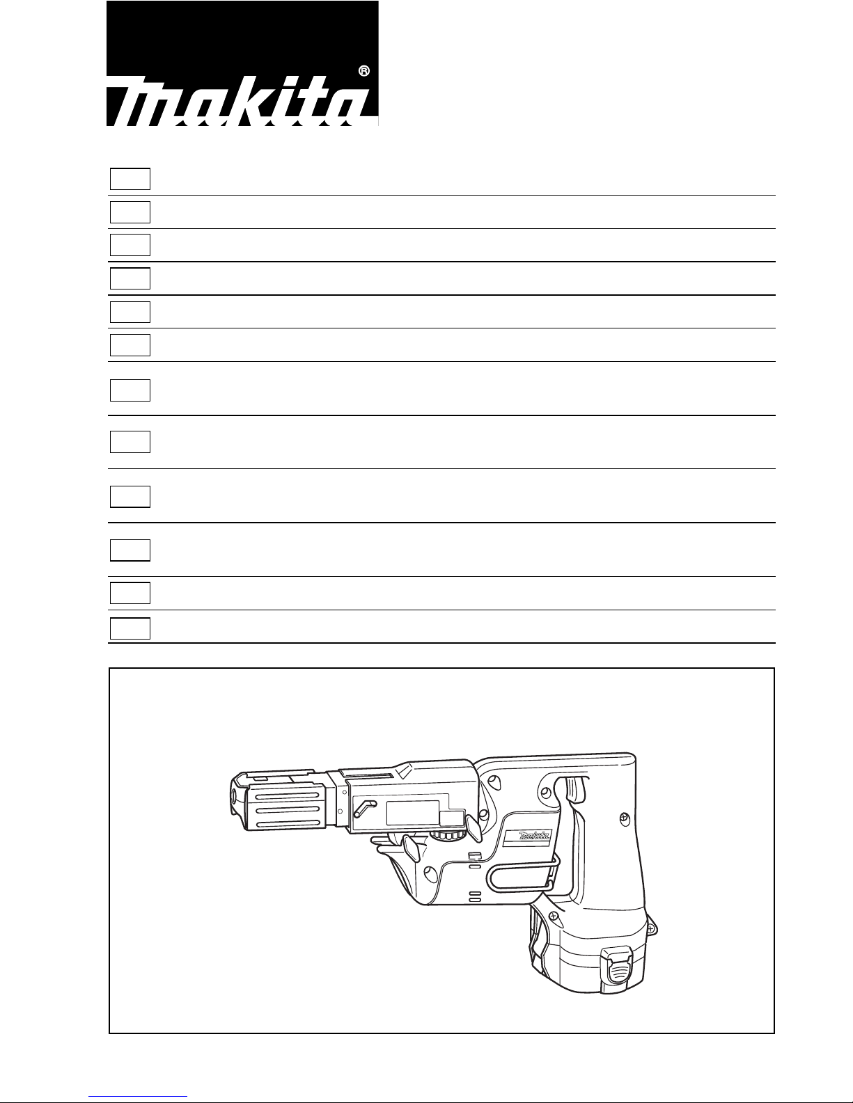
Plaatsen en verwijderen van accu (Fig. 1)
• Schakel de machine altijd uit voordat een accu
geplaatst of verwijdert wordt.
• Om de accu te verwijderen, neemt u het uit het gereed-
schap terwijl u de duwknoppen aan beide zijden van de
accu indrukt.
• Om de accu te installeren, past u de rug op de accu in
de groef in de behuizing van het gereedschap, en dan
schuift u de accu naar binnen. Schuif de accu zo ver
mogelijk erin, totdat het met een klikgeluid vergrendelt.
Indien u dit niet doet, kan de accu per ongeluk uit het
gereedschap vallen en uzelf of anderen verwonden.
• Als de accu moeilijk in de houder komt, probeer het
dan niet met geweld in te duwen. Indien de accu er niet
gemakkelijk ingaat, dan houdt u het verkeerd om.
Instellen van de gewenste schroeflengte (Fig. 2)
Er zijn 3 vergrendelbare schroeflengte-instellingen. Om
de gewenste instelling te krijgen, trekt u de stopvoet naar
buiten terwijl u de hendel naar beneden drukt totdat het
getal van de gewenste schroeflengte (aangeduid op de
plaat) net boven de bovenrand van de behuizing komt te
staan. Raadpleeg de onderstaande tabel voor de verhou-
ding tussen de getallen aangeduid op de plaat en de
overeenkomstige schroeflengten.
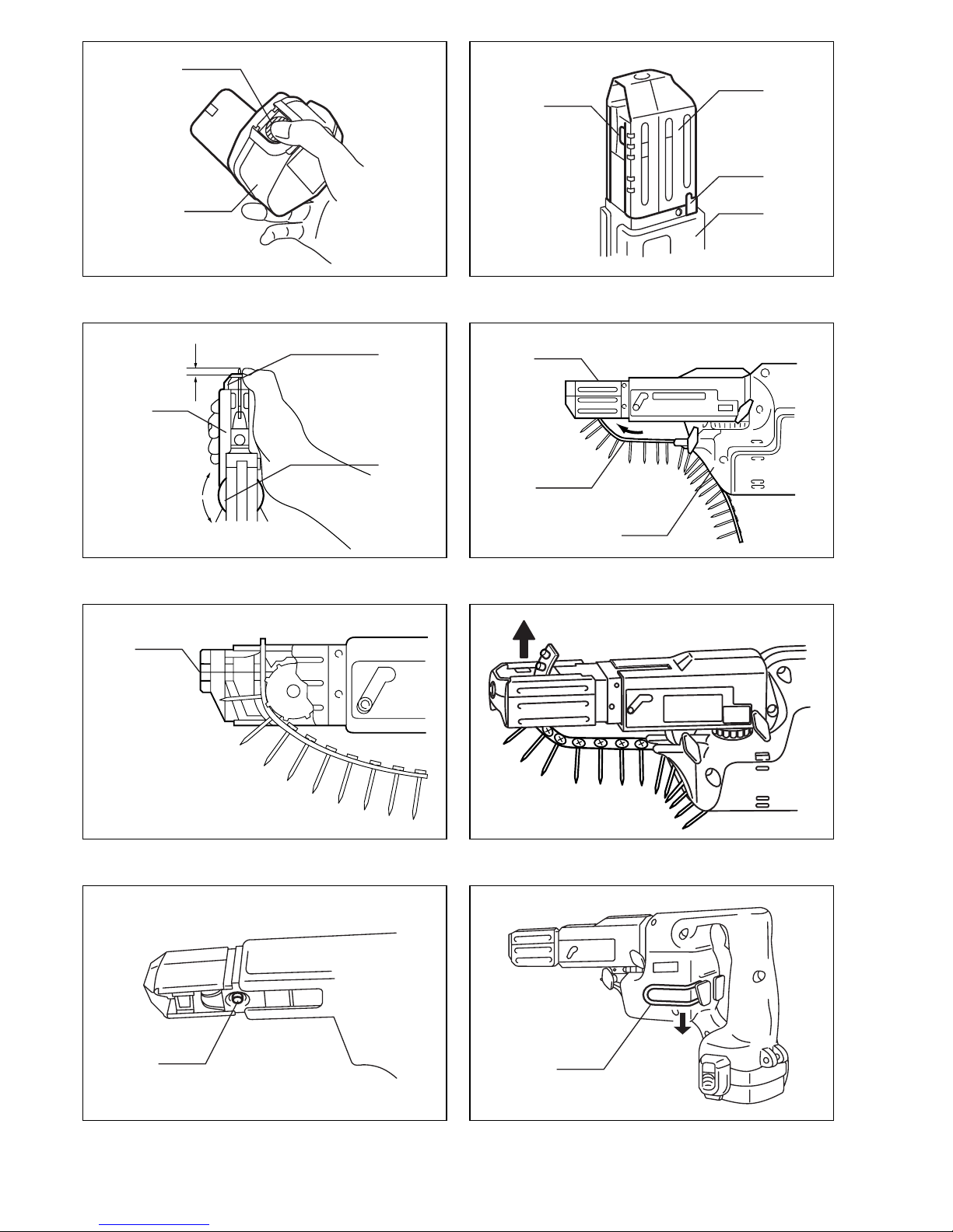
Instellen van de schroefdiepte (Fig. 3)
Druk de stopvoet zo ver mogelijk in. Houd hem in deze
positie en draai de regelknop tot de bitpunt ongeveer
5 mm uit de stopvoet steekt. Draai een testschroef in.
Indien de schroefkop boven het inschroefoppervlak uit-
steekt, moet u de regelknop in de “A” richting draaien;
indien de schroefknop verzonken zit, moet u de regel-
knop in de “B” richting draaien.
Aanbrengen van de schroefstrip (Fig. 4 en 5)
Steek de schroefstrip door de schroefgeleider. Steek
hem vervolgens door de toevoerbox tot de eerste schroef
naast de inschroefpositie komt te zitten.
Verwijderen van de schroefstrip (Fig. 6 en 7)
Om de schroefstrip te verwijderen, trekt u hem gewoon in
de richting van het pijltje. Als u de omkeerknop indrukt,
kunt u de schroefstrip in de omgekeerde richting van het
pijltje eruit trekken.
Draaghaak (Fig. 8)
De draaghaak is handig om het gereedschap tijdelijk vast
te haken. Hij kan aan de linker- of rechterzijde van het
gereedschap worden bevestigd. Om de draaghaak te
bevestigen of te verwijderen, moet u deze verwijden door
zijn onderste gedeelte in de richting van het pijltje te
drukken.
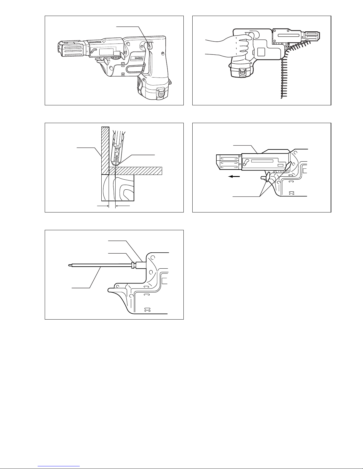
Werking van de trekschakelaar (Fig. 9)
LET OP:
Alvorens de accu in het gereedschap te plaatsen, moet u
altijd controleren of de trekschakelaar juist werkt en bij
het loslaten naar de “OFF” positie terugkeert.
Om het gereedschap in te schakelen, drukt u gewoon de
trekschakelaar in. Om het gereedschap uit te schakelen,
de trekschakelaar loslaten.
Bediening voor inschroeven (Fig. 10)
Schakel het gereedschap in door de trekschakelaar in te
drukken. Houd het gereedschap recht en stevig tegen
het inschroefoppervlak. Een schroef wordt automatisch
naar de inschroefpositie gebracht en ingeschroefd.
LET OP:
• Controleer altijd de bit zorgvuldig op slijtage alvorens
met het inschroeven te beginnen. Vervang de bit indien
deze versleten is, aangezien de schroeven anders
slecht vastgezet zullen worden.
• Houd het gereedschap altijd recht tegen het inschroef-
oppervlak. Wanneer u het gereedschap schuin houdt,
kunnen de schroefkoppen beschadigd raken, zal de bit
rapper verslijten, en zullen de schroeven mogelijk niet
goed vastgezet zijn.
• Houd het gereedschap altijd stevig tegen het inschroef-
oppervlak totdat de schroef goed erin zit. Als u dit niet
doet, zullen de schroeven mogelijk niet goed vastgezet
zijn.
• Draai geen schroef in op een andere schroef die reeds
is ingeschroefd.
• Gebruik het gereedschap niet zonder schroeven erin.
Daardoor zal het inschroefoppervlak namelijk worden
beschadigd.
• Indien de toevoerbox tijdens het inschroeven niet meer
soepel werkt, spuit dan autoboenwas (spuittype was)
op zijn glijvlakken. Nooit smeren.
Schroeven in hoeken (Fig. 11)
Dit gereedschap kan worden gebruikt voor inschroeven
op minimaal 15 mm van de muur vandaan, zoals afge-
beeld in Fig. 11.
LET OP:
Indien u inschroeft op een plaats die minder dan 15 mm
van de muur is verwijderd, of inschroeft terwijl de stop-
voet de muur raakt, kunnen de schroefkoppen bescha-
digd raken en zal de bit rapper verslijten. Bovendien
zullen de schroeven dan mogelijk niet goed vastgezet
zijn en kan het gereedschap defect raken.
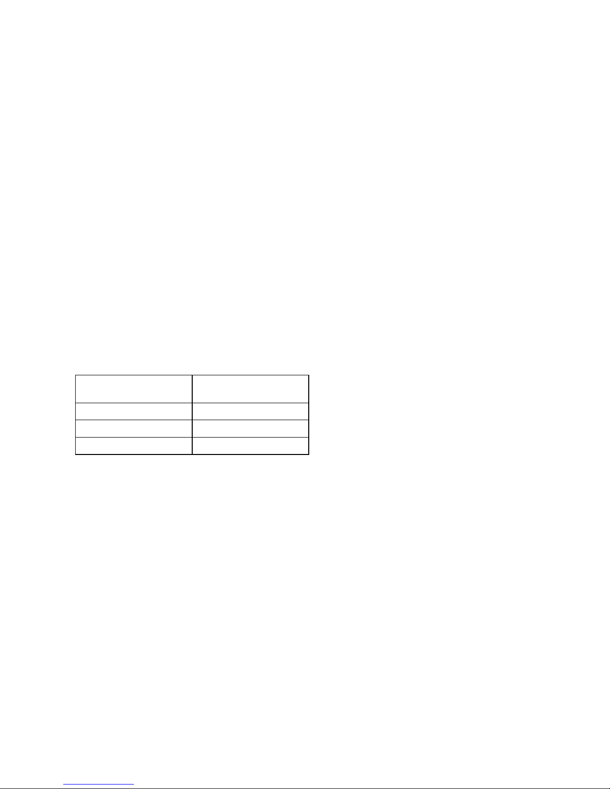
Installeren of verwijderen van de bit
(Fig. 12 en 13)
Belangrijk:
Controleer altijd of het gereedschap is uitgeschakeld en
de accu is losgekoppeld alvorens de boor te installeren
of te verwijderen.
Draai de vleugelschroeven los waarmee de behuizing is
bevestigd. Verwijder de behuizing in de richting van het
pijltje. Duw de stofkap in de richting van het lager en trek
de bit eruit. Wanneer de stofkap niet tot tegen het lager
kan worden geduwd, verdraai de bit dan een beetje en
probeer opnieuw.
Om de bit te installeren, steekt u hem in de houder terwijl
u hem lichtjes draait. Controleer na het installeren altijd
of de bit goed vastzit door eraan te trekken.
Getal aangeduid
op de plaat
Schroeflengtebereik
(mm)
25/28 25 – 28
32 28 – 35
40 35 – 41

18
ONDERHOUD
LET OP:
Controleer altijd of de machine is uitgeschakeld en de
accu is losgekoppeld vooraleer onderhoud uit te voeren
aan de machine.
Opdat het gereedschap veilig en betrouwbaar blijft, die-
nen alle reparaties, onderhoud of afstellingen te worden
uitgevoerd bij een erkend Makita service centrum.
ACCESSOIRES
LET OP:
• Deze accessoires of hulpstukken worden aanbevolen
voor gebruik met het Makita gereedschap dat in deze
gebruiksaanwijzing is beschreven. Bij gebruik van
andere accessoires of hulpstukken bestaat er gevaar
voor persoonlijke verwonding. Gebruik de accessoires
of hulpstukken uitsluitend voor hun bestemde doel.
Raadpleeg het dichtstbijzijnde Makita Servicecentrum
voor verder advies of bijzonderheden omtrent deze
accessoires.
• Schroefstrip voor gestapelde muren
• Phillips bit
• Diverse types originele Makita accu’s en acculaders
• Plastic draagkoffer

40
ENH102-4
EC-DECLARATION OF CONFORMITY
We declare under our sole responsibility that this product
is in compliance with the following standards of standard-
ized documents,
EN60745, EN55014
in accordance with Council Directives, 89/336/EEC and
98/37/EC.
DÉCLARATION DE CONFORMITÉ CE
Nous déclarons sous notre entière responsabilité que ce
produit est conforme aux normes des documents stan-
dardisés suivants,
EN60745, EN55014
conformément aux Directives du Conseil, 89/336/CEE et
98/37/EG.
CE-KONFORMITÄTSERKLÄRUNG
Hiermit erklärt wir unter unserer alleinigen Verantwor-
tung, daß dieses Produkt gemäß den Ratsdirektiven 89/
336/EWG und 98/37/EG mit den folgenden Normen von
Normendokumenten übereinstimmen:
EN60745, EN55014.
DICHIARAZIONE DI CONFORMITÀ
CON LE NORME DELLA COMUNITÀ EUROPEA
Dichiariamo sotto la nostra sola responsabilità che
questo prodotto è conforme agli standard di documenti
standardizzati seguenti:
EN60745, EN55014
secondo le direttive del Consiglio 89/336/CEE e 98/37/
CE.
EG-VERKLARING VAN CONFORMITEIT
Wij verklaren hierbij uitsluitend op eigen verant-
woordelijkheid dat dit produkt voldoet aan de volgende
normen van genormaliseerde documenten,
EN60745, EN55014
in overeenstemming met de richtlijnen van de Raad 89/
336/EEC en 98/37/EC.
DECLARACIÓN DE CONFORMIDAD DE LA CE
Declaramos bajo nuestra sola responsabilidad que este
producto cumple con las siguientes normas de docu-
mentos normalizados,
EN60745, EN55014
de acuerdo con las directivas comunitarias, 89/336/EEC
y 98/37/CE.
Yasuhiko Kanzaki
CE 2005
Director Amministratore
Directeur Directeur
Direktor Director
MAKITA INTERNATIONAL EUROPE LTD.
Michigan Drive, Tongwell, Milton Keynes,
Bucks MK15 8JD, ENGLAND
Responsible manufacturer: Produttore responsabile:
Fabricant responsable :Verantwoordelijke fabrikant:
Verantwortlicher Hersteller: Fabricante responsable:
Makita Corporation Anjo Aichi Japan
ENGLISH
FRANÇAISE
DEUTSCH
ITALIANO
NEDERLANDS
ESPAÑOL

41
ENH102-4
DECLARAÇÃO DE CONFORMIDADE DA CE
Declaramos sob inteira responsabilidade que este
produto obedece às seguintes normas de documentos
normalizados,
EN60745, EN55014
de acordo com as directivas 89/336/CEE e 98/37/CE do
Conselho.
EU-DEKLARATION OM KONFORMITET
Vi erklærer hermed påeget ansvar, at dette produkt er i
overensstemmelse med de følgende standarder i de
normsættende dokumenter,
EN60745, EN55014
i overensstemmelse med Rådets Direktiver 89/336/EEC
og 98/37/EC.
EG-DEKLARATION OM ÖVERENSSTÄMMELSE
Under eget ansvar deklarerar vi härmed att denna
produkt överensstämmer med följande standardiseringar
för standardiserade dokument,
EN60745, EN55014
i enlighet med EG-direktiven 89/336/EEC och 98/37/EC.
EUs SAMSVARS-ERKLÆRING
Vi erklærer påeget ansvar at dette produktet er i over-
ensstemmelse med følgende standard i de standardis-
erte dokumenter:
EN60745, EN55014,
i samsvar med Råds-direktivene, 89/336/EEC og 98/37/
EC.
VAKUUTUS EC-VASTAAVUUDESTA
Yksinomaisesti vastuullisina ilmoitamme, ettätämätuote
on seuraavien standardoitujen dokumenttien standardien
mukainen,
EN60745, EN55014
neuvoston direktiivien 89/336/EEC ja 98/37/EC mukai-
sesti.
∆ΗΛΩΣΗ ΣΥΜΜΟΡΦΩΣΗΣ ΕΚ
∆ηλώνουµε υπ την µοναδική µας ευθύνη τι αυτ
το προιν βρίσκεται σε Συµφωνία µε τα ακλουθα
πρτυπα τυποποιηµένων εγγράφων
EN60745 EN55014
σύµφωνα µε τις Οδηγίες του Συµβουλίου 89/336/
EEC και 98/37/ΚE.
Yasuhiko Kanzaki
CE 2005
Director Direktor
DirektørJohtaja
Direktör∆ιευθυντής
MAKITA INTERNATIONAL EUROPE LTD.
Michigan Drive, Tongwell, Milton Keynes,
Bucks MK15 8JD, ENGLAND
Fabricante responsável: Ansvarlig produsent:
Ansvarlig fabrikant: Vastaava valmistaja:
Ansvarig tillverkare: Υπεύθυνος κατασκευαστής:
Makita Corporation Anjo Aichi Japan
PORTUGUÊS
DANSK
SVENSKA
NORSK
SUOMI
ΕΛΛΗΝΙΚΑ

42
ENG001-2
For European countries only
Noise and Vibration
The typical A-weighted sound pressure level is not more
than 70 dB (A).
The noise level under working may exceed 85 dB (A).
–Wear ear protection. –
The typical weighted root mean square acceleration
value is not more than 2.5 m/s2.
These values have been obtained according to
EN60745.
Pour les pays d’Europe uniquement
Bruit et vibrations
Le niveau de pression sonore pondere type A ne
dépasse pas 70 dB (A).
Le niveau de bruit en fonctionnement peut dépasser
85 dB (A).
–Porter des protecteurs anti-bruit. –
L’accélération pondérée ne dépasse pas 2,5 m/s2.
Ces valeurs ont étéobtenues selon EN60745.
Nur für europäische Länder
Geräusch- und Vibrationsentwicklung
Der typische A-bewertete Schalldruckpegel beträgt nicht
mehr als 70 dB (A).
Der Lärmpegel kann während des Betriebs 85 dB (A)
überschreiten.
–Gehörschutz tragen. –
Der gewichtete Effektivwert der Beschleunigung beträgt
nicht mehr als 2,5 m/s2.
Diese Werte wurden gemäß EN60745 erhalten.
Modello per l’Europa soltanto
Rumore e vibrazione
Il livello di pressione sonora pesata secondo la curva A
non supera i 70 dB (A).
Il livello di rumore durante il lavoro potrebbe superare gli
85 dB (A).
–Indossare i paraorecchi. –
Il valore quadratico medio di accellerazione non supera i
2,5 m/s2.
Questi valori sono stati ottenuti in conformitàEN60745.
Alleen voor Europese landen
Geluidsniveau en trilling
Het typische A-gewogen geluidsdrukniveau is niet meer
dan 70 dB (A).
Tijdens het werken kan het geluidsniveau 85 dB (A) over-
schrijden.
–Draag oorbeschermers. –
De typische gewogen effectieve versnellingswaarde is
niet meer dan 2,5 m/s2.
Deze waarden werden verkregen in overeenstemming
met EN60745.
Para países europeos solamente
Ruido y vibración
El nivel de presión sonora ponderada A no sobrepasa los
70 dB (A).
El nivel de ruido en condiciones de trabajo puede que
sobrepase los 85 dB (A).
–Póngase protectores en los oídos. –
El valor ponderado de la aceleración no sobrepasa los
2,5 m/s2.
Estos valores han sido obtenidos de acuerdo con
EN60745.
ENGLISH
FRANÇAISE
DEUTSCH
ITALIANO
NEDERLANDS
ESPAÑOL

43
ENG001-2
Só para países Europeus
Ruído e vibração
O nível normal de pressão sonora A éinferior a
70 dB (A).
O nível de ruído durante o trabalho pode exceder
85 dB (A).
–Utilize protectores para os ouvidos –
O valor médio da aceleração éinferior a 2,5 m/s2.
Estes valores foram obtidos de acordo com EN60745.
Kun for lande i Europa
Lyd og vibration
Det typiske A-vægtede lydtryksniveau overstiger ikke
70 dB (A).
Støjniveauet under arbejde kan overstige 85 dB (A).
–Bær høreværn. –
Den vægtede effektive accelerationsværdi overstiger ikke
2,5 m/s2.
Disse værdier er beregnet i overensstemmelse med
EN60745.
Endast för Europa
Buller och vibration
Den typiska-A-vägda ljudtrycksnivån överstiger inte
70 dB (A).
Bullernivån under pågående arbete kan överstiga
85 dB (A).
–Använd hörselskydd –
Det typiskt vägda effektivvärdet för acceleration översti-
ger inte 2,5 m/s2.
Dessa värden har erhållits i enlighet med EN60745.
Gjelder bare land i Europa
Støy og vibrasjon
Det vanlige A-belastede lydtrykksnivåoverskrider ikke
70 dB (A).
Under bruk kan støynivået overskride 85 dB (A).
–Benytt hørselvern. –
Den vanlig belastede effektiv-verdi for akselerasjon over-
skrider ikke 2,5 m/s2.
Disse verdiene er beregnet eller målt i samsvar med
EN60745.
Vain Euroopan maat
Melutaso ja tärinä
Tyypillinen A-painotettu äänenpainetaso ei ylitä
70 dB (A).
Melutaso työpaikalla saattaa ylittää 85 dB (A).
–Käytäkuulosuojaimia. –
Tyypillinen kiihtyvyyden painotettu tehollisarvo ei ylitä
2,5 m/s2.
Nämäarvot on mitattu normin EN60745 mukaisesti.
Μνο για χώρες της Ευρώπης
ρυβος και κραδασµς του µοντέλου
Η τυπική Α-µετρούµενη ηχητική πίεση δεν ξεπερνά
τα 70 dB (A).
Η ένταση ήχου υπο συνθήκες εργασίας µπορεί να
µπερβεί τα 85 dB (A).
– Φοράτε ωτοασπίδες. –
Η τυπική αξία της µετρούµενης ρίζας του µέσου
τετραγώνου της επιτάχυνσης δεν ξεπερνά τα
2 5 m/s2.
Αυτές οι τιµές έχουν σηµειωθεί σύµφωνα µε το
EN60745.
PORTUGUÊS
DANSK
SVENSKA
NORSK
SUOMI
ΕΛΛΗΝΙΚΑ

Makita Corporation
Anjo, Aichi, Japan
884269F999
Other manuals for 6835D
5
Table of contents
Languages:
Other Makita Power Screwdriver manuals

Makita
Makita DFR540 User manual

Makita
Makita 6833 User manual

Makita
Makita DFT043F User manual

Makita
Makita DFL083F User manual

Makita
Makita 6805BV User manual

Makita
Makita FS4300X User manual

Makita
Makita XAD02 User manual

Makita
Makita XT255R User manual

Makita
Makita XRF01 User manual

Makita
Makita 6807 User manual

Makita
Makita FS4200 User manual

Makita
Makita 6821 User manual

Makita
Makita DFS441 User manual

Makita
Makita 6830 User manual

Makita
Makita DFR440X User manual

Makita
Makita 6827 User manual

Makita
Makita FS2700 User manual

Makita
Makita DDF083RTJ User manual

Makita
Makita 6805BV User manual

Makita
Makita 6821 User manual