Aero-East-Europe SILA 450 C Owner's manual
SILA 450 C
P O H
Signature:___________________________
Civil Aviation Directorate of the Republic of Serbia
Stamp
Original date of approval
Serial No.: XXXXXX –AEE –XXXX
This airplane is to be operated in compliance with information and limitations
contained herein. September 2015

OPERATION MANUAL SILA 450 c AERO EAST EUROPE
Date 01.09.2015. Revision 00 Page | 2
FOREWORD_____________________________________________________
Foreword
This Pilot’s Operating Handbook (POH or Handbook) has been prepared by
Aero-East-Europe to familiarize operators with the SILA 450 C airplane. Read
this Handbook carefully. It provides operational procedures that will assure the
operator obtains the performance published in the manual, data designed to
allow the most efficient use of the airplane, and basic information for
maintaining the airplane in a “like new” condition.
SILA 450 C is the high-wing, single engine, two seat aircraft, with a semi -
monocoque fuselage structure, make from approved aeronautical aluminum. The
wing airfoil is NACA 5417 and it’s same along wing span, wings are rectangular
with sweep angle equal to zero, twist angle of -2° from wing root to wing tip and
dihedral angle of 0,5°. Wings are made from approved aeronautical aluminum,
with wing tips from epoxy plastic. Wings are connected to the top of the
fuselage and supported by two struts on each wing. Wings are main lift surfaces
which supporting the aircraft in flight. The tail surfaces are with classic design.
Vertical tail has a rudder, the airfoil of vertical tail is NACA 0010, vertical tail
sweep angle is equal to 40°. Horizontal tail has elevator with trim tab, the airfoil
of horizontal tail is NACA 0010, the horizontal tail is rectangular with sweep
angle equal to zero. Aircraft landing gear is non –retractable, tricycle with nose
leg. Power plant consists from four –stroke engine and tractor propeller with
clockwise rotation. Engine mount is fabricated from welded chrome
molybdenum steel. The engine compartment is from fire proof epoxy plastic.
Happy Flying!
Aero-East-Europe

OPERATION MANUAL SILA 450 c AERO EAST EUROPE
Date 01.09.2015. Revision 00 Page | 3
____________________Record of revisions_____________________
Any revision of the POH need to be noticed in table below.
Log of revisions
Revision No.:
Date released
Section
Reason for revision
Approved by
00
01.09.2015
1
Initial issue
00
01.09.2015
2
Initial issue
00
01.09.2015
3
Initial issue
00
01.09.2015
4
Initial issue
00
01.09.2015
5
Initial issue
00
01.09.2015
6
Initial issue
00
01.09.2015
7
Initial issue
00
01.09.2015
8
Initial issue
00
01.09.2015
9
Initial issue

OPERATION MANUAL SILA 450 c AERO EAST EUROPE
Date 01.09.2015. Revision 00 Page | 4
____________________Table of Contents___________________
SECTION 1 –GENERAL INFORMATION.............................................................6
SECTION 2 –LIMITATIONS.............................................................................10
SECTION 3 –EMERGENCY PROCEDURES ........................................................17
SECTION 4 –NORMAL PROCEDURES .............................................................23
SECTION 5 –PERFORMANCE .........................................................................33
SECTION 6 –WEIGHT AND BALANCE .............................................................38
SECTION 7 –AIRPLANE & SYSTEM DESCRIPTION ...........................................40
SECTION 8 –AIRPLANE HANDLING SERVICING AND MAINTENANCE..............56
SECTION 9 –SUPPLEMENTS...........................................................................75

OPERATION MANUAL SILA 450 c AERO EAST EUROPE
Date 01.09.2015. Revision 00 Page | 5
________________List of effective pages______________________
SECTION 1 SECTION 6
Page Issue Revision Rev. date Page Issue Revision Rev. date
6 01 00 01.09.2015 37 01 00 01.09.2015
7 01 00 01.09.2015 38 01 00 01.09.2015
8 01 00 01.09.2015
9 01 00 01.09.2015 SECTION 7
Page Issue Revision Rev. date
SECTION 2 40 01 00 01.09.2015
Page Issue Revision Rev. date 41 01 00 01.09.2015
10 01 00 01.09.2015 42 01 00 01.09.2015
11 01 00 01.09.2015 43 01 00 01.09.2015
12 01 00 01.09.2015 44 01 00 01.09.2015
13 01 00 01.09.2015 45 01 00 01.09.2015
14 01 00 01.09.2015 46 01 00 01.09.2015
15 01 00 01.09.2015 47 01 00 01.09.2015
16 01 00 01.09.2015 48 01 00 01.09.2015
49 01 00 01.09.2015
50 01 00 01.09.2015
SECTION 3 51 01 00 01.09.2015
Page Issue Revision Rev. date 52 01 00 01.09.2015
17 01 00 01.09.2015 53 01 00 01.09.2015
18 01 00 01.09.2015 54 01 00 01.09.2015
19 01 00 01.09.2015 55 01 00 01.09.2015
20 01 00 01.09.2015 SECTION 8
21 01 00 01.09.2015 Page Issue Revision Rev. date
22 01 00 01.09.2015
56 01 00 01.09.2015
SECTION 4 57 01 00 01.09.2015
Page Issue Revision Rev. date 58 01 00 01.09.2015
23 01 00 01.09.2015 59 01 00 01.09.2015
24 01 00 01.09.2015 60 01 00 01.09.2015
25 01 00 01.09.2015 61 01 00 01.09.2015
26 01 00 01.09.2015 62 01 00 01.09.2015
27 01 00 01.09.2015 63 01 00 01.09.2015
28 01 00 01.09.2015 64 01 00 01.09.2015
29 01 00 01.09.2015 65 01 00 01.09.2015
30 01 00 01.09.2015 66 01 00 01.09.2015
31 01 00 01.09.2015 67 01 00 01.09.2015
68 01 00 01.09.2015
SECTION 5 69 01 00 01.09.2015
Page Issue Revision Rev. date 70 01 00 01.09.2015
32 01 00 01.09.2015 71 01 00 01.09.2015
33 01 00 01.09.2015 72 01 00 01.09.2015
34 01 00 01.09.2015 73 01 00 01.09.2015
35 01 00 01.09.2015 74 01 00 01.09.2015
36 01 00 01.09.2015
SECTION 9
Page Issue Revision Rev. date
75 01 00 01.09.2015
76 01 00 01.09.2015
77 01 00 01.09.2015

OPERATION MANUAL SILA 450 c AERO EAST EUROPE
Date 01.09.2015. Revision 00 Page | 6
GENERAL INFORMATION
SECTION 1
_____TABLE OF CONTENTS_______________________________________
•1.1 Introduction 7
•1.2 Certification Basis 7
•1.3 Performances –specifications 7
•1.4 Dimensions 8
•1.5 Descriptive Data 9
-1.5.1 Engine 9
-1.5.2 Propeller 9
-1.5.3 Fuel 9
-1.5.4 Oil 9
-1.5.5 Maximum Certificated Weight 9
•1.6 Warnings, cautions and notes 9

OPERATION MANUAL SILA 450 c AERO EAST EUROPE
Date 01.09.2015. Revision 00 Page | 7
GENERAL INFORMATION
1.1 INTRODUCTION
Section 1 provides basic data and information of general interest. Values stated in this
chapter are based on calculation and tested values during flight tests and aircraft
exploitation. Intention of aircraft manufacturer is to explain in safe manner using and
exploitation of SILA 450 C.
Basic aircraft characteristics are stated in foreword of this manual.
1.2 CERTIFICATION BASIS
This flight manual has been prepared according to EASA CS –VLA and complies with LTF –UL
(German Airworthiness Requirements) and Serbian Regulation for Ultra-Light Airplanes.
1.3 PERFORMANCES-SPECIFICATIONS(values according calculations and experience)
SPEED:
Maximum 223 kmh (120kts)
Cruise, 75% power 204 kmh (110 kts)
Stall speed flaps up 70 kmh (40 kts)
CRUISE: Recommended with fuel allowance for engine start, takeoff, climb flight to
destination or closest alternative airport and air field 45 minutes reserve, average
consumption is 15 liters per hour or 3,97 gallons per hour
RATE OF CLIMB AT SEA LEVEL 5,6 m/s –1000 FPM
SERVICE CEILING 3. 658 m –12000 FT
TAKEOFF PERFORMANCE
Ground Roll 90 meters –295 FT
LANDING PERFORMANCE
Ground Roll 140 meters –460 FT
STALL SPEESDS (KCAS)
Flaps Up, Power Off 83 km/h –38 Knots
Flaps Down, Power Off 64 km/h –34Knots
MAXIMUM TAKE-OFF WEIGH 472,5 kg
STANDARD EMPTY WEIGHT 280 kg without parachute, 292,5 kg with parachute
MAXIMUM USEFUL LOAD 180 kg=MTOW - (empty weight aircraft )
FUEL CAPACITY 100L ( 96 lit useful)–23,8 gallons (22,8 gallons useful)
PROPELLER: Diameter 1600 –1700 millimeters
NOTE:
The performance figures are estimated basically on the indicated weights, standard
atmospheric conditions 15 °C (59 °F, 288,15K) and 101.325 kPa (14.696 psi, 1.01325 bar), sea
level, hard-surface, dry runways and no wind. They are calculated values derive from
calculations conducted by the Aero East Europe Company under carefully documented
conditions and will vary with individual airplanes and numerous factors affecting flight
performance.

OPERATION MANUAL SILA 450 c AERO EAST EUROPE
Date 01.09.2015. Revision 00 Page | 8
1.4 DIMENSIONS GENERAL INFORMATION
5,90 ft
9 460mm/31,04ft
9 460 mm/31,04ft
1270mm
4,17ft
6470mm/21,2 ft
2400mm
7,87ft
1700mm/
5,58ft
1800 mm

OPERATION MANUAL SILA 450 c AERO EAST EUROPE
Date 01.09.2015. Revision 00 Page | 9
GENERAL INFORMATION
1.5 DESCRIPTIVE DATA
1.5.1 ENGINE
- Number of engines: 1 piece
- Engine Manufacturer: BRP Powertrain GmbH & Co KG
- Engine Model Number: Rotax series , 912UL/ULS 2/ S/F/A
- Engine Type: Normally aspirated, direct-drive, air-cooled, horizontally opposed,
Carburetor equipped, four-cylinder engine with 319.8 cu.in.
Displacement
- Horsepower Rating and Engine Speed: 80/100 rated HP at 5800 RPM
1.5.2 PROPELLER
- Propeller Manufacturer: WOODCOMP Czech Republik. MT Propeller and others
- Propeller Model Number: Woodcomp……., MTV-33-1-A and others
- Number of Blades: two and three blades etc
- Propeller Diameter: Maximum: 1700 millimeters, Minimum: 1600 millimeters.
- Propeller Type: Tractor right
1.5.3 FUEL
Approved Fuel Grades: BMB 95 Octane alternative 100LL
Fuel Capacity:
Total Capacity: 90 lit–23,8 gallons
Total Capacity Each Tank: 45 lit –11,9 gallons
Total Usable: ( 86 lit useful) (22,8 g useful) gallons.
1.5.4 OIL
Oil Grade (Specifications): 10w-40 (5w-50)
Straight semisynthetic oil: As provided in Engine Maintenance Manual.
1.5.5 MAXIMUM AIRCRAFT WEIGHT
-Maximum Takeoff Weight: 472,5 Kg
-Maximum Landing Weight: 472,5 Kg
1.6 WARNINGS, CAUTIONS AND NOTES
The next definitions are connected with warnings, cautions and notes used in Pilot Operation Handbook
WARNING
It means that non –observation of the appropriate procedure leads to an immediate or significant
decreasing of flight safety.
CAUTIONS
It means that the non –observation of the appropriate procedure to a minor or to a more or less long
term decreasing of flight safety.
NOTES
Draws attention to any special item or occurrence not related to safety but which is important or unusual.

OPERATION MANUAL SILA 450 c AERO EAST EUROPE
Date 01.09.2015. Revision 00 Page | 10
LIMITATIONS
SECTION 2
_____TABLE OF CONTENTS_______________________________________
• 2.1 Introduction 11
• 2.2 Air Speed Limitations 11
• 2.3 Airspeed Indicator Markings 11
• 2.4 Power Plant Limitations 12
• 2.5 Power Plant Limitations Markings 12
• 2.6 Weight Limits 13
• 2.7 Center of Gravity Limits 13
• 2.8 Maneuver Limits 14
• 2.9 Maneuvering load factors 14
• 2.10 Flight crew 14
• 2.11 Kinds of Operational Limits 15
• 2.12 Fuel Limitations 15
• 2.13 Maximum passenger seating 16
• 2.14 Limitation placards 16

OPERATION MANUAL SILA 450 c AERO EAST EUROPE
Date 01.09.2015. Revision 00 Page | 11
LIMITATIONS
2.1 INTRODUCTION
Section 2 describing limitations which are must not to be exceed for safe flight. All
limitations are market with appropriate placards.
2.2 AIR SPEED LIMITATIONS
Air Speed Limitations and their operational significance are shown in Figure 2-1.
Maneuvering speed shown apply to normal category operations
SPEED
IAS
REMARKS
VNE
Never Exceed Speed
223 km/h
120(knots)
Do not exceed this speed
in any operation
VH
Maximum Structural
Cruising Speed
204 km/h
110(knots)
Do not exceed this speed
except in smooth air.
VRA
Maximum speed for
rough air
183 km/h
99 knots
Exceed this speed only in
smooth air
VA
Maneuvering Speed
165 km/h
89 (knots)
Do not make full or abrupt
control movements above
this speed
VFE
Maximum Flaps ExtSpeed:
19° - 38° Flaps
½ -Full Flaps
106 km/h
57 (knots)
Do not exceed this speed
with flaps down. Take care
about flaps setting
VNE
Maximum gear operating
speed
223 km/h
120(knots)
The landing gear is not
retractable
Figure 2-1. Airspeed Limitations
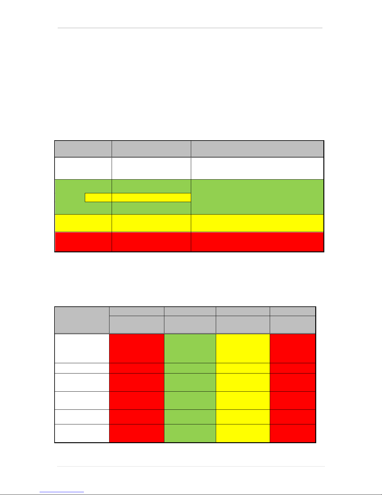
2.3 AIR SPEED INDICATOR MARKINGS
Airspeed Indicator markings and their color code significance are shown in figure 2-2.
MARKING
IAS VALUE OF RANGE
SIGNIFICANCE
White Arc
From 1.1 VS0
72 –106 km/h
38 –57(knots)
Full Flap Operating Range. Lower limit is maximum
weight V in landing configuration. Upper limits
maximum speed permissible with full flaps extend.
Green Arc
91 km/h(49 knots)
Normal Operating Range. Lower limit is maximum
weight V at most forward C.G. with flaps retracted.
Upper limit is maximum structural cruising speed.
bar
165km/h(89knots)
From 1.1 VS1
183km/h(99 knots)
Yellow Arc
183 –223 km/h
223 –120 (knots)
Operating must be conducted with
caution and only in smooth air.
Red Line
2223 km/h
=120 (knoots)
Maximum speed for all operations!!!
Figure 2-2. Airspeed Indicator Makings
Remark : The color of placard on Air Speed Indicator is the same as in Figure 2 –2
WARNING
Do not exceed speed of 223,6 km/h(120,6 knots) at any operation and at under any circumstances.

OPERATION MANUAL SILA 450 c AERO EAST EUROPE
Date 01.09.2015. Revision 00 Page | 12
LIMITATIONS
2.4 POWER PLANT LIMITATIONS
-Engine Manufacturer: BRP-Powertrain GmbH & Co KG
-Engine Model Number: 912 UL
-Maximum Power: 80 HP rating and others
-Engine Operating Limits or Takeoff and continuous Operations:
Maximum Engine Speed: 5800 RPM maximum for 5 min
Maximum Oil Temperature: According Engine Manual
NOTE
Static engine RPM should be 5100+250 under clear weather without wind
-Oil Pressure
Minimum: 0.8 bar at 3000 rpm - 12 psi at 3000 rpm
Maximum: 7 bar 101.5 psi.
-Oil Grade (Specification): 10w –40 / 5w - 50
-Propeller Manufacturer: Woodcomp s.r.o. and others
-Propeller Model Number: Woodcomp SR 3000 and others
-Propeller Diameter: 1700 millimeters
NOTE:
The static RPM range at full throttle 5800rpm per 5 minute in case
- redactor per engine 2:43 100hp is 2389 rpm
- redactor 2:27 per engine 80hp is 2555 rpm
2.5 POWER PLANT INSTRUMENT MARKINGS ROTAX 912 UL
Power plant instrument markings and their color code significance are shown in figure 2-3
INSTRUMENT
RED LINE
GREEN ARC
YELLOW ARC
RED LINE
MINIMUM
LIMIT
NORMAL
OPERATING
MAXIMUM
LIMIT
Tachometer:
Sea Level
5000 ft
10000 ft
1400 RPM
1400 –5500 RPM
1400 –5500 RPM
1400 –5500 RPM
5500 –5800 RPM
5500 –5800 RPM
5500 –5800 RPM
5800 RPM
5800 RPM
5800 RPM
Oil Temperature
50 0C
90 –110 0C
50-90;110-130°C
130 0C
Oil Pressure
0,83 bar
12 psi
2 –5 bar
29 –73 psi
0,83 –2;5 –7 bar
12 –29;73 –102 psi
7 bar
102 psi
CHT
50 0C
50 –130 0C
130-135 0C
135 0C
Fuel Quantity
0 l
0 gallons
8 –100 l
2,12–26,4 gallons
0 –8 l
0 –2,12 gallons
100 l
26,4 gallons
Suction
6,5 l/h
12,5 –17,5 l/h
N/A
25 l/h
Figure 2-3 Power Plant Instrument Markings
Remark : The colors on engine instruments are the same as in Figure 2 –3

OPERATION MANUAL SILA 450 c AERO EAST EUROPE
Date 01.09.2015. Revision 00 Page | 13
LIMITATIONS
2.6 WEIGHT LIMITS
Maximum take –off weight
472,5 kg
Maximum landing weight
472,5 kg
Maximum empty weight
297,5 kg
Maximum weight in baggage compartment
20kg
Figure 2-4
2.7 CENTER OF GRAVITY LIMITS
Center of Gravity range has two different categories for empty airplane and for different
load cases. Center of Gravity range for empty airplane is calculated for the worst possible
combination of loads from occupants, baggage(if any) and fuel, and considered the worst
combination of weights during flight.
Forward limit C.G. (empty airplane)
23,0% of MAC or 292 mm from leading edge
Aft limit C.G. (empty airplane)
27,0% of MAC or 340 mm from leading edge
Forward limit C.G. (MTOW)
29% of MAC or 368 mm from leading edge
Aft limit C.G. (MTOW)
34% of MAC or 432 mm from leading edge
Figure 2-5
Warning
Aircraft commander is obligate to take care about center of gravity positions by weighing the aircraft
and take care about approved weights for aircraft loadings (if any baggage, crew and fuel)
Picture 2 showing weighing plan of the SILA 450 C, and figure 2-6 showing calculation for determining
Center of Gravity position
Picture 2 –Weighing plan
Figure 2-6: Calculation of Center of Gravity positions
Weighing point
Scale reading Ri [kg]
TareTi[kg]
Net WeightNWi= Ri –Ti[kg]
Nosewheel
RN= [kg]
TN = [kg]
NWN = [kg]
Left wheel
RL = [kg]
TL = [kg]
NWL = [kg]
Right wheel
RR= [kg]
TR = [kg]
NWR = [kg]
Total weight [lbs] or [kg]
TW = NWN+ NWL+ NWR+ +
TW = [kg]
C.G. position from Datum (Leading edge) [mm]
C.G.=
C.G. = [mm]
C.G. position [% MAC]

OPERATION MANUAL SILA 450 c AERO EAST EUROPE
Date 01.09.2015. Revision 00 Page | 14
LIMITATIONS
2.8 MANEUVER LIMITS
This airplane is designed for non-aerobatic operations.
These include any maneuvers incidental to normal flying, stalls (except whip stalls), lazy
eights, chandelles, and turns in which the angle of bank is not more than 60°.
WARNING
Aerobatic maneuvers, including spins, are not approved.
Non –aerobatic maneuvers are approved and they are listed below:
MANEUVER RECOMMENDED ENTRY SPEED*
Chandelles 167 km/h –90 (knots)
Lazy Eights 157 km/h –85 (knots)
Steep Turns 148 km/h –80 (knots)
WARNING
Abrupt use of the controls is prohibited above 165 km/h - 89 (knots)
CAUTION
Aerobatics that may impose high loads should not be attempted.
The important thing to bear in mind in flight maneuvers is that the airplane is clean in
aerodynamic design and will increase up speed quickly with the nose down. Proper speed
control is an essential requirement for execution of any maneuver, and care should always
be exercised to avoid excessive speed which in turn can impose excessive loads. In the
execution of all maneuvers, avoid abrupt use of the controls. Intentional spins with flaps
extended are prohibited.
2.9 MANEUVERING LOAD FACTORS
According certification specifications and project calculations the load factor limits are the
next, according maximum take –off weight and acceleration of gravity “g”
Flaps retracted 0°
Maximum positive load
factor;VA,VNE
+4
Maximum negative load factor
-2
Figure 2 –7: Limit load factor with flaps retracted
Flaps deployed 19-38°
(take-off and landing)
Maximum positive load factor
+2
Maximum negative load factor
0
Figure 2 –7: Limit load factor with flaps deployed
2.10 FLIGHT CREW
Minimum flight crew 1 pilot
Maximum flight crew 2 (1pilot + 1copilot)
Two seated aircraft side by side.

OPERATION MANUAL SILA 450 c AERO EAST EUROPE
Date 01.09.2015. Revision 00 Page | 15
LIMITATIONS
2.11 KINDS OF OPERATIONAL LIMITS
The airplane is equipped for day VFR and may be equipped for night VFR and/or IFR
operations in any case no icing conditions. The reference to types of flight operations on the
operating limitations placard reflects equipment installed at the time of Airworthiness
issuance.
WARNING
A flight into known icing conditions is strictly prohibited.
2.12 FUEL LIMITATIONS
Fuel Capacity:
Total Capacity: 90 lit –23,8 gallons
Total Capacity Each Tank: 45 lit –11,9 gallons
Total reserve tank capacity: 10 liters –2,6 gallons (only if installed)
Total Usable: 86 lit useful –22,8 gallons
Approved fuel grades:
95 Octane –Premium automotive benzene
100 LL –AV Gas
Special instructions for fuel management
During replenishment of fuel tanks in wing take care to aircraft be parked at plane surface to
assure proper estimate of level of fuel and fulfillment of fuel tanks.
NOTE
Especially take attention in case when determining fuel quantity, is necessary that airplane
be park at absolutely horizontal surface, it’s important to prevent spilling fuel from tanks
because tanks are communicative. According to above mentioned facts parking at uneven
surface can cause emphasis of fuel from inferior tank. Parking at absolutely horizontal
surface is also important to have reliable information of fuel quantity.
OPERATION MANUAL SILA 450 c AERO EAST EUROPE
Date 01.09.2015. Revision 00 Page | 16
LIMITATIONS
2.13 MAXIMUM PASSENGER SEATING
SILA 450 C is two seated aircraft, as above mentioned this aircraft utility is sport and
amateur flying and isn’t intended for passenger travel. Two seated aircraft, side by side, left
pilot side, and right copilot side. Limitations for crew are stated in Chapter 2.10 of this
document.
2.14 LIMITATIONS PLACARDS
Limitation placards are installed on aircraft instruments and they are the same as depicted in
this document, Chapter 2.3 and 2.5. the figures are shown below.
Airspeed Indicator markings and their color code significance
MARKING
IAS VALUE OF RANGE
SIGNIFICANCE
White Arc
From 1.1 VS0
72 –106 km/h
39 –57(knots)
Full Flap Operating Range. Lower limit is maximum
weight V in landing configuration. Upper limits
maximum speed permissible with full flaps extend.
Green Arc
91 km/h(49knots)
Normal Operating Range. Lower limit is maximum
weight V at most forward C.G. with flaps retracted.
Upper limit is maximum structural cruising speed.
bar
165km/h(89knots)
From 1.1 VS1
183 km/h(99 knots)
Yellow Arc
183 –223 km/h
223 –120 (knots)
Operating must be conducted with
caution and only in smooth air.
Red Line
2223 km/h
=120 (knoots)
Maximum speed for all operations!!!
NOTE
The difference between stated speeds and airspeed indicator marking is consequence from
tested and certified values because of safety margin of 10%. Test pilots and manufacturing
pilots are with much higher experience than amateur pilots.
Power plant instrument markings and their color code significance
INSTRUMENT
RED LINE
GREEN ARC
YELLOW ARC
RED LINE
MINIMUM
LIMIT
NORMAL
OPERATING
MAXIMUM
LIMIT
Tachometer:
Sea Level
5000 ft
10000 ft
1400 RPM
1400 –5500 RPM
1400 –5500 RPM
1400 –5500 RPM
5500 –5800 RPM
5500 –5800 RPM
5500 –5800 RPM
5800 RPM
5800 RPM
5800 RPM
Oil Temperature
50 0C
90 –110 0C
50-90;110-130°C
130 0C
Oil Pressure
0,83 bar
12 psi
2 –5 bar
29 –73 psi
0,83 –2;5 –7 bar
12 –29;73 –102 psi
7 bar
102 psi
CHT
50 0C
50 –130 0C
130 –135 0C
135 0C
Fuel Quantity
0 l
0 gallons
8 –90 l
2,12–23,8 gallons
0 –8 l
0 –2,12 gallons
90 l
23,8 gallons
Suction
7,5 l/h
14,5 –18,5 l/h
N/A
27 l/h

OPERATION MANUAL SILA 450 c AERO EAST EUROPE
Date 01.09.2015. Revision 00 Page | 17
EMERGENCY PROCEDURES
SECTION 3
_____TABLE OF CONTENTS_______________________________________
•3.1 Introduction 18
•3.2 Airspeeds for Emergency Procedures depend of emergency
case but in general best rate of glide (circa 92-120 km/h 50 - 65knots) 18
•3.3 Engine Failures 18
-3.3.1 Engine Failure during Takeoff Run 18
-3.3.2 Engine Failure immediately after T/O 18
-3.3.3 Engine Failure during Flight 19
•3.4 Forced Landings 19
-3.4.1 Emergency Landing without Engine Power 19
-3.4.2 Precautionary Landing with Engine Power 19
•3.5 Landing with flat main tire 19
•3.6 Landing with a defective landing gear 20
•3.7 Fires 20
-3.7.1 During Start on Ground 20
-3.7.2 Engine Fire in Flight 20
-3.7.3 Electrical Fire in Flight 20
-3.7.4 Cabin Fire 21
-3.7.5 Wing Fire 21
•3.8 Glide 21
•3.9 Approach and landing with flaps retracted 21
•3.10 Recovery from unintentional spin 22
•3.11 Other emergencies 22
-3.11.1 Vibrations 22

OPERATION MANUAL SILA 450 c AERO EAST EUROPE
Date 01.09.2015. Revision 00 Page | 18
EMERGENCY PROCEDURES
3.1 INTRODUCTION
This Section provides checklists and amplified procedures for coping with
emergencies that might occur. Emergencies caused by airplane or engine malfunctions are
extremely rare if proper preflight inspections and maintenance are practiced. Enrooted
weather emergencies can be minimized or eliminated by careful flight planning and good
judgment when unexpected weather is encountered. However, should an emergency arise,
the basic guidelines described in this section should be considered and applied as necessary
to fix the problem.
3.2 AIRSPEEDS FOR EMERGENCY OPERATION
Engine Failure After Takeoff:
Wing Flaps Up 120 km/h - 65(knots) IAS
Wing Flaps Down 102 km/h - 55(knots) IAS
Maneuvering Speed (maximum glide):
472,5 kg –1041 lbs. 139 km/h - 75(knots) IAS
420,0 kg –926 lbs. 130 km/h - 70(knots) IAS
367,5 kg –810 lbs. 111 km/h - 60(knots) IAS
Precautionary approach speed for Landing With Engine Power
472,5 kg –1041 lbs. 120 km/h - 65(knots) IAS
420,0 kg –926 lbs. 102 km/h - 55(knots) IAS
367,5 kg –810 lbs. 92 km/h - 50(knots) IAS
Precautionary approach speed for Landing Without Engine Power:
Wing Flaps Up 120 km/h - 65(knots) IAS
Wing Flaps Down 102 km/h - 55(knots) IAS
3.3 ENGINE FAILURES
3.3.1 ENGINE FAILURE DURING TAKEOFF RUN
[1] Throttle --- IDLE
[2] Brakes --- APPLY
[3] Ignition Switch --- OFF
[4] Master Switch --- OFF
3.3.2 ENGINE FAILURE IMMEDIATELY AFTER TAKEOFF
[1] Airspeed --- 120 km/h –65(knots) IAS(flaps up)
--- 102 km/h –55(knots) IAS (flaps down)
[3] Fuel Selector Valve --- OFF
[4] Ignition Switch --- OFF
[5] Wing Flaps --- AS REQUIRED
[6] Master Switch --- OFF

OPERATION MANUAL SILA 450 c AERO EAST EUROPE
Date 01.09.2015. Revision 00 Page | 19
EMERGENCY PROCEDURES
3.3.3 ENGINE FAILURE DURING FLIGHT
[1] Airspeed --- 120 km/h - 65(knots) IAS
[2] Check fuel quantity and selector --- ON
[3] Carburetor Heat --- ON
[4] Chock push --- OFF
[5] Check engine instruments (temperature, etc)
[6] Push start engine buttons, repeat several times
[7] During recovery procedure, all the time take care about speed, attitude and selected field !
3.4 FORCED LANDINGS
3.4.1 EMERGENCY LANDING WITHOUT ENGINE POWER
[1] Airspeed --- 120 km/h - 65(knots) IAS (flaps up)
--- 111 km/h - 60(knots) IAS (flaps down)
[2] General Fuel Valve --- OFF
[3] Change in flight direction up to 30° to left and right side. Highly recommended!
[4] Wing Flaps --- AS REQUIRED, USUALY IN FINAL APPROACH
[5] Master Switch --- OFF
[6] Doors --- UNLATCH PRIOR TO TOUCHDOWN
[7] Touchdown --- SLIGHTLY TAIL LOW
[8] Brakes --- APPLY HEAVILY(if necessary)
3.4.2 PRECAUTIONARY LANDING WITH ENGINE POWER
[1] Wing Flaps --- 19°
[2] Airspeed --- 111 km/h - 60(knots) IAS
[3] Selected Field --- FLY OVER, noting terrain, obstruction and wind direction
from safe altitude and airspeed,
[4] Electrical Switches --- OFF
[5] Wing Flaps --- 38° (on final approach)
[6] Speed at final approach --- 84 kmh 45 kts
[7] Master Switch --- On
[8] Doors --- UNLATCH PRIOR TO TOUCHDOWN
[9] Touchdown --- SLIGHTLY TAIL LOW
[10] Ignition Switch --- OFF AFTER TOUCHDOWN
[11] Brakes --- APPLY HEAVILY(if necessary)
3.5 LANDING WITH FLAT MAIN TIRE
[1] Wing Flaps --- DEPLOYED
[2] Elevator control --- NOSE UP
[3] Expect rotation after runway touch, to the flat tyre side
[3] Aileron and rudder --- BANK TOWARD GOD TIRE
[4] Rudder control --- KEEP NOSE STRAIGHT TO BALANCE ROTATION
[5] Touchdown --- GOOD TIRE FIRST
[6] Brakes --- APPLY CAREFULLY WITH HIGHER FORCE AT GOOD TYRE

OPERATION MANUAL SILA 450 c AERO EAST EUROPE
Date 01.09.2015. Revision 00 Page | 20
EMERGENCY PROCEDURES
3.6 LANDING WITH A DEFECTIVE LANDING GEAR
[1] Wing Flaps --- FULLY DEPLOYED
[2] Elevator control --- NOSE HIGH
[3] Aileron control --- ZERO POSITION
[4] Rudder control --- KEEP NOSE STRAIGHT
[5] Airspeed --- ADJUST TO MINIMUM POSSIBLE(CCA 65 KMH-35KNOTS)
[6] Touchdown --- SLIGHTLY AND GENTLE
[7] Landing roll --- KEEP STRAIGHT DIRECTION
[8] Brakes --- APPLY (DEPPEND FROM DEFECTED LEG)
Remark : If nose wheel damaged try to hold nose wheel over runaway using elevator till
total decreasing of speed and kinetic energy.
3.7 FIRES
3.7.1 DURING START ON GROUND
[1] Mixture --- IDLE CUT-OFF
[2] Fuel Selector Valve --- OFF
[3] Master Switch --- OFF
[4] Cabin Heat and Air --- OFF (except overhead vents)
[5] Leave the aircraft --- IMMEDIATELY
[6] TRY TO EXTINGUISH FIRE WITH EXTINGUISHER (IF POSSIBLE)
[7] Call fire department and start with extinguishing fire if safe
3.7.2 ENGINE FIRE IN FLIGHT
[1] Mixture --- IDLE CUT-OFF
[2] Fuel Selector Valve --- OFF
[3] Master Switch --- OFF
[4]Flying in such a way that the air stream rejects the fire away from the airplane
[5] Cabin Heat and Air --- OFF (except overhead vents)
[6] Airspeed --- TAKE CARE ABOUT STALL SPEED
[7] Precautionary Landing --- EXECUTE
3.7.3 ELECTRICAL FIRE IN FLIGHT
[1] Master Switch --- OFF
[2] Avionics Power Switch --- OFF
[3] All other switches
(except ignition switch) --- OFF
[4] Continue with flight in opposite direction from fire to ensure that flue gases not entered
to cockpit.
[5] Cabin Air/Heat --- CLOSED (except overhead vents)
Table of contents
Popular Tools manuals by other brands


Westfalia
Westfalia 927325 Original instructions

Grizzly
Grizzly T28929 instructions

BGS technic
BGS technic 8776 instruction manual

Powermatic
Powermatic JTG-10Q Operating instructions and parts manual

SUHNER ABRASIVE
SUHNER ABRASIVE LLC 4-TOP Technical document

Chicago Pneumatic
Chicago Pneumatic CP7269 Series Operator's manual